Page 8 of 148
EM-8
PREPARATION
Revision: 2006 November2007 350Z
(Kent-Moore No.)
Tool nameDescription
Power toolLoosening bolts and nuts
TORX socketRemoving and installing flywheel
Size: T55
(—)
Manual lift table caddyRemoving and installing engine
(J24239-01)
Cylinder head bolt wrenchLoosening and tightening cylinder head bolt,
and used with angle wrench [SST:
KV10112100 (BT8653-A)]
a: 13 (0.51) dia.
b: 12 (0.47)
c: 10 (0.39)
Unit: mm (in)
(—)
1. Compression gauge
2. AdapterChecking compression pressure
(—)
Spark plug wrenchRemoving and installing spark plug
(—)
Valve seat cutter setFinishing valve seat dimensions
PBIC0190E
PBIC1113E
ZZA1210D
NT583
ZZA0008D
PBIC3874E
NT048
Page 101 of 148

ENGINE ASSEMBLY
EM-101
C
D
E
F
G
H
I
J
K
L
MA
EM
Revision: 2006 November2007 350Z
ENGINE ASSEMBLYPFP:10001
Removal and InstallationNBS00012
WARNING:
�Situate vehicle on a flat and solid surface.
�Place chocks at front and back of rear wheels.
�For engines not equipped with engine slingers, attach proper slingers and bolts described in
PARTS CATALOG.
CAUTION:
�Always be careful to work safely, avoid forceful or uninstructed operations.
�Do not start working until exhaust system and engine coolant are cool enough.
�If items or work required are not covered by the engine section, refer to the applicable sections.
�Always use the support point specified for lifting.
�Use either 2-pole lift type or separate type lift as best you can. If board-on type is used for
unavoidable reasons, support at the rear axle jacking point with transmission jack or similar tool
before starting work, in preparation for the backward shift of center of gravity.
�For supporting points for lifting and jacking point at rear axle, refer to GI-39, "Garage Jack and
Safety Stand" .
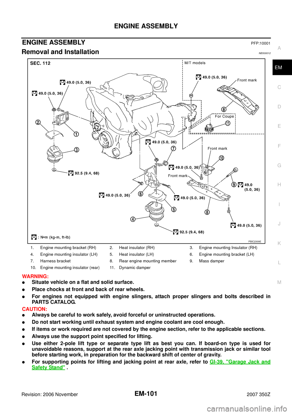
1. Engine mounting bracket (RH) 2. Heat insulator (RH) 3. Engine mounting Insulator (RH)
4. Engine mounting insulator (LH) 5. Heat insulator (LH) 6. Engine mounting bracket (LH)
7. Harness bracket 8. Rear engine mounting member 9. Mass damper
10. Engine mounting insulator (rear) 11. Dynamic damper
PBIC2309E
Page 108 of 148

EM-108
CYLINDER BLOCK
Revision: 2006 November2007 350Z
DISASSEMBLY
1. Remove engine assembly from vehicle, and separate front suspension member and transmission from
engine. Refer to EM-101, "
ENGINE ASSEMBLY" .
2. Remove engine mounting brackets (RH and LH). Refer to EM-101, "
ENGINE ASSEMBLY" .
3. Remove the parts that may restrict installation of engine to widely use engine stand.
NOTE:
The procedure is described assuming that you use a widely use engine stand holding the surface, to
which transmission is installed.
�Remove clutch cover and clutch disk (M/T models). Refer to CL-16, "CLUTCH DISC, CLUTCH
COVER" .
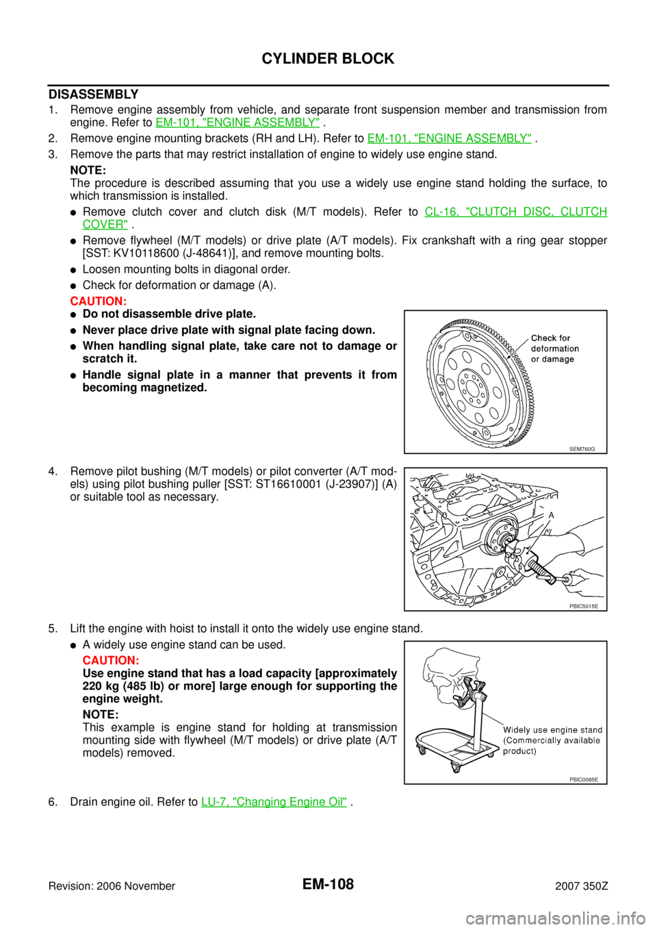
�Remove flywheel (M/T models) or drive plate (A/T models). Fix crankshaft with a ring gear stopper
[SST: KV10118600 (J-48641)], and remove mounting bolts.
�Loosen mounting bolts in diagonal order.
�Check for deformation or damage (A).
CAUTION:
�Do not disassemble drive plate.
�Never place drive plate with signal plate facing down.
�When handling signal plate, take care not to damage or
scratch it.
�Handle signal plate in a manner that prevents it from
becoming magnetized.
4. Remove pilot bushing (M/T models) or pilot converter (A/T mod-
els) using pilot bushing puller [SST: ST16610001 (J-23907)] (A)
or suitable tool as necessary.
5. Lift the engine with hoist to install it onto the widely use engine stand.
�A widely use engine stand can be used.
CAUTION:
Use engine stand that has a load capacity [approximately
220 kg (485 lb) or more] large enough for supporting the
engine weight.
NOTE:
This example is engine stand for holding at transmission
mounting side with flywheel (M/T models) or drive plate (A/T
models) removed.
6. Drain engine oil. Refer to LU-7, "
Changing Engine Oil" .
SEM760G
PBIC5015E
PBIC0085E
Page 118 of 148

EM-118
CYLINDER BLOCK
Revision: 2006 November2007 350Z
Flywheel (M/T models)
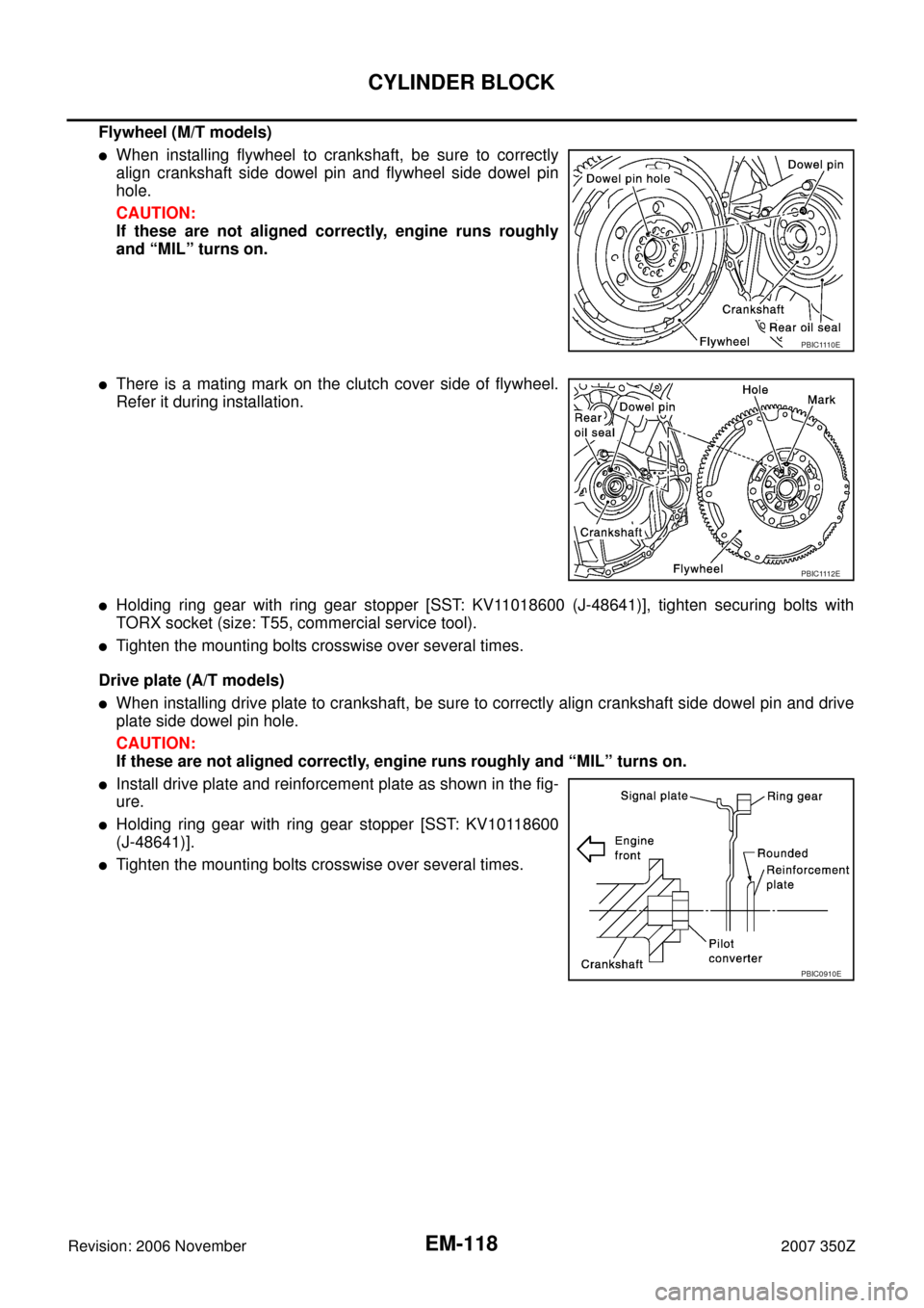
�When installing flywheel to crankshaft, be sure to correctly
align crankshaft side dowel pin and flywheel side dowel pin
hole.
CAUTION:
If these are not aligned correctly, engine runs roughly
and “MIL” turns on.
�There is a mating mark on the clutch cover side of flywheel.
Refer it during installation.
�Holding ring gear with ring gear stopper [SST: KV11018600 (J-48641)], tighten securing bolts with
TORX socket (size: T55, commercial service tool).
�Tighten the mounting bolts crosswise over several times.
Drive plate (A/T models)
�When installing drive plate to crankshaft, be sure to correctly align crankshaft side dowel pin and drive
plate side dowel pin hole.
CAUTION:
If these are not aligned correctly, engine runs roughly and “MIL” turns on.
�Install drive plate and reinforcement plate as shown in the fig-
ure.
�Holding ring gear with ring gear stopper [SST: KV10118600
(J-48641)].
�Tighten the mounting bolts crosswise over several times.
PBIC1110E
PBIC1112E
PBIC0910E