Page 48 of 148
EM-48
FRONT TIMING CHAIN CASE
Revision: 2006 November2007 350Z
2. Hammer dowel pins (right and left) into front timing chain case
up to a point close to taper in order to shorten protrusion length.
3. Install new front oil seal on the front timing chain case.
�Apply new engine oil to both oil seal lip and dust seal lip.
�Install it so that each seal lip is oriented as shown in the fig-
ure.
�Using suitable drift [outer diameter: 60 mm (2.36 in)] (A),
press-fit oil seal until it becomes flush with front timing chain
case end face.
�Make sure the garter spring is in position and seal lip is not
inverted.
4. Install front timing chain case as follows:
PBIC2615E
SEM715A
PBIC4971E
Page 63 of 148

TIMING CHAIN
EM-63
C
D
E
F
G
H
I
J
K
L
MA
EM
Revision: 2006 November2007 350Z
c. Align rear timing chain case and water pump assembly with dowel pins (right and left) on cylinder block
and install rear timing chain case.
�Make sure O-rings stay in place during installation to cylinder block.
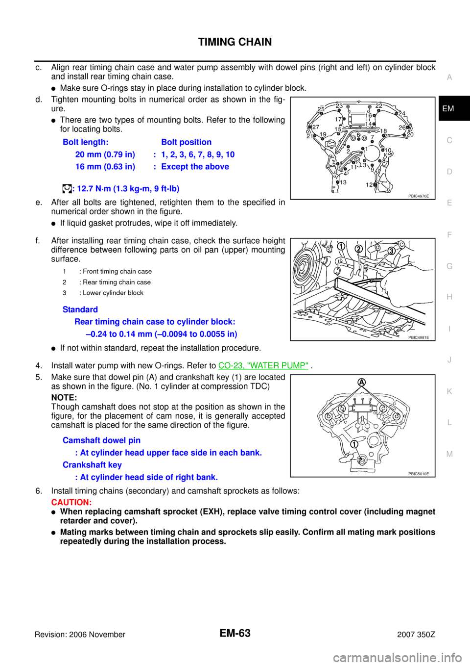
d. Tighten mounting bolts in numerical order as shown in the fig-
ure.
�There are two types of mounting bolts. Refer to the following
for locating bolts.
e. After all bolts are tightened, retighten them to the specified in
numerical order shown in the figure.
�If liquid gasket protrudes, wipe it off immediately.
f. After installing rear timing chain case, check the surface height
difference between following parts on oil pan (upper) mounting
surface.
�If not within standard, repeat the installation procedure.
4. Install water pump with new O-rings. Refer to CO-23, "
WATER PUMP" .
5. Make sure that dowel pin (A) and crankshaft key (1) are located
as shown in the figure. (No. 1 cylinder at compression TDC)
NOTE:
Though camshaft does not stop at the position as shown in the
figure, for the placement of cam nose, it is generally accepted
camshaft is placed for the same direction of the figure.
6. Install timing chains (secondary) and camshaft sprockets as follows:
CAUTION:
�When replacing camshaft sprocket (EXH), replace valve timing control cover (including magnet
retarder and cover).
�Mating marks between timing chain and sprockets slip easily. Confirm all mating mark positions
repeatedly during the installation process.Bolt length: Bolt position
20 mm (0.79 in) : 1, 2, 3, 6, 7, 8, 9, 10
16 mm (0.63 in) : Except the above
: 12.7 N·m (1.3 kg-m, 9 ft-lb)
PBIC4976E
1 : Front timing chain case
2 : Rear timing chain case
3 : Lower cylinder block
Standard
Rear timing chain case to cylinder block:
–0.24 to 0.14 mm (–0.0094 to 0.0055 in)
PBIC4981E
Camshaft dowel pin
: At cylinder head upper face side in each bank.
Crankshaft key
: At cylinder head side of right bank.
PBIC5010E
Page 111 of 148
![NISSAN 350Z 2007 Z33 Engine Mechanical Workshop Manual CYLINDER BLOCK
EM-111
C
D
E
F
G
H
I
J
K
L
MA
EM
Revision: 2006 November2007 350Z
19. Remove lower cylinder block as follows:
Screw M8 bolt [Pitch: 1.25 mm (0.049 in), Length: approx. 50
mm (1.97 in)] NISSAN 350Z 2007 Z33 Engine Mechanical Workshop Manual CYLINDER BLOCK
EM-111
C
D
E
F
G
H
I
J
K
L
MA
EM
Revision: 2006 November2007 350Z
19. Remove lower cylinder block as follows:
Screw M8 bolt [Pitch: 1.25 mm (0.049 in), Length: approx. 50
mm (1.97 in)]](/manual-img/5/765/w960_765-110.png)
CYLINDER BLOCK
EM-111
C
D
E
F
G
H
I
J
K
L
MA
EM
Revision: 2006 November2007 350Z
19. Remove lower cylinder block as follows:
Screw M8 bolt [Pitch: 1.25 mm (0.049 in), Length: approx. 50
mm (1.97 in)] into bolt holes (A) shown in the figure. Then
equally tighten each bolt, and remove lower cylinder block.
CAUTION:
�Be careful not to damage the mating surface.
�Do not tighten bolts too much.
�Do not insert screw driver, this will damage the mating
surface.
20. Remove crankshaft.
21. Pull rear oil seal out from rear end of crankshaft.
22. Remove main bearings and thrust bearings from cylinder block and lower cylinder block.
CAUTION:
�Identify installation positions, and store them without mixing them up.
�Be careful not to drop main bearing, and to scratch the surface.
23. Remove oil jet.
ASSEMBLY
1. Fully air-blow engine coolant and engine oil passages in cylinder block, cylinder bore and crankcase to
remove any foreign material.
CAUTION:
Use a goggles to protect your eye.
: Engine front
PBIC5016E
: Engine front
PBIC5047E
Page 127 of 148

CYLINDER BLOCK
EM-127
C
D
E
F
G
H
I
J
K
L
MA
EM
Revision: 2006 November2007 350Z
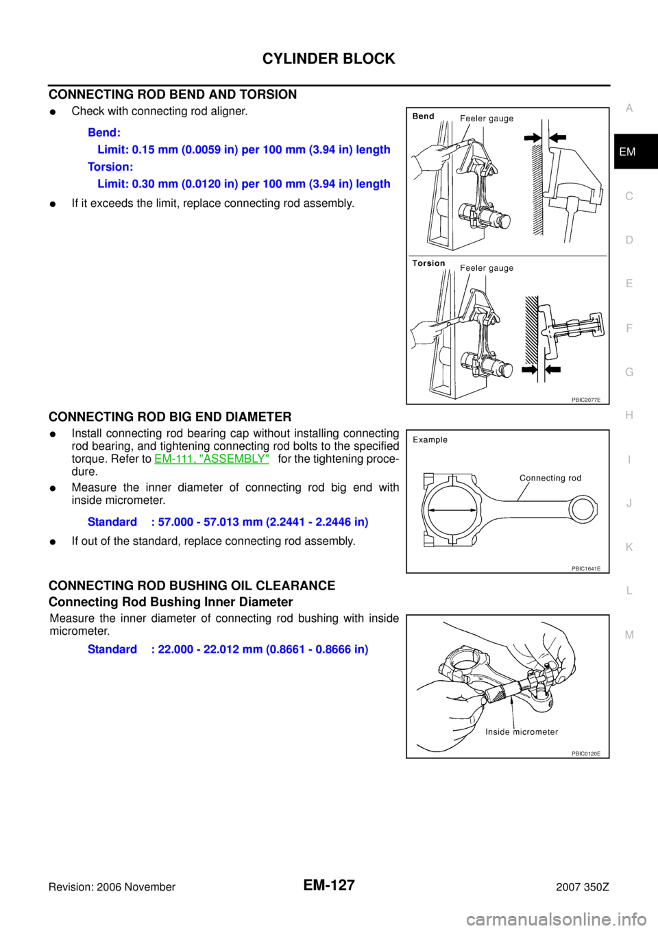
CONNECTING ROD BEND AND TORSION
�Check with connecting rod aligner.
�If it exceeds the limit, replace connecting rod assembly.
CONNECTING ROD BIG END DIAMETER
�Install connecting rod bearing cap without installing connecting
rod bearing, and tightening connecting rod bolts to the specified
torque. Refer to E M - 111 , "
ASSEMBLY" for the tightening proce-
dure.
�Measure the inner diameter of connecting rod big end with
inside micrometer.
�If out of the standard, replace connecting rod assembly.
CONNECTING ROD BUSHING OIL CLEARANCE
Connecting Rod Bushing Inner Diameter
Measure the inner diameter of connecting rod bushing with inside
micrometer.Bend:
Limit: 0.15 mm (0.0059 in) per 100 mm (3.94 in) length
To r s i o n :
Limit: 0.30 mm (0.0120 in) per 100 mm (3.94 in) length
PBIC2077E
Standard : 57.000 - 57.013 mm (2.2441 - 2.2446 in)
PBIC1641E
Standard : 22.000 - 22.012 mm (0.8661 - 0.8666 in)
PBIC0120E
Page 139 of 148
SERVICE DATA AND SPECIFICATIONS (SDS)
EM-139
C
D
E
F
G
H
I
J
K
L
MA
EM
Revision: 2006 November2007 350Z
CYLINDER HEAD
Unit: mm (in)
Valve Dimensions
Unit: mm (in) Items Standard Limit
Head surface distortion Less than 0.03 (0.0012) 0.1 (0.004)
Normal cylinder head height “H” 126.3 - 126.5 (4.972 - 4.980) —
PBIC0924E
Valve head diameter “D”Intake 36.6 - 36.9 (1.441 - 1.453)
Exhaust 30.2 - 30.5 (1.189 - 1.201)
Valve length “L”Intake 97.13 (3.8240)
Exhaust 94.67 (3.7272)
Valve stem diameter “d”Intake 5.965 - 5.980 (0.2348 - 0.2354)
Exhaust 5.962 - 5.970 (0.2347 - 0.2350)
Valve seat angle “α”Intake
45°15′ - 45°45′
Exhaust
Valve margin “T”Intake 1.1 (0.043)
Exhaust 1.3 (0.051)
Valve margin “T” limit0.5 (0.020)
Valve stem end surface grinding limit 0.2 (0.008)
SEM188
Page 140 of 148
EM-140
SERVICE DATA AND SPECIFICATIONS (SDS)
Revision: 2006 November2007 350Z
Valve Guide
Unit: mm (in)
Items Standard Oversize (Service) [0.2 (0.008)]
Va l v e g u i d eOuter diameter 10.023 - 10.034 (0.3946 - 0.3950) 10.223 - 10.234 (0.4025 - 0.4029)
Inner diameter (Finished size) 6.000 - 6.018 (0.2362 - 0.2369)
Cylinder head valve guide hole diameter 9.975 - 9.996 (0.3927 - 0.3935) 10.175 - 10.196 (0.4006 - 0.4014)
Interference fit of valve guide 0.027 - 0.059 (0.0011 - 0.0023)
Items Standard Limit
Valve guide clearanceIntake 0.020 - 0.053 (0.0008 - 0.0021) 0.08 (0.0031)
Exhaust 0.030 - 0.056 (0.0012 - 0.0022) 0.09 (0.0035)
Projection length “L” 12.6 - 12.8 (0.496 - 0.504)
SEM950E