TIMING CHAIN
EM-67
C
D
E
F
G
H
I
J
K
L
MA
EM
Revision: 2006 November2007 350Z
CAUTION:
Do not overtighten slack guide mounting bolts. It is normal
for a gap to exist under the bolt seats when mounting bolts
are tightened to specification.
9. Install the timing chain tensioner (primary) with the following procedure:
a. Pull plunger stopper tab up (or turn lever downward) so as to
remove plunger stopper tab from the ratchet of plunger.
NOTE:
Plunger stopper tab and lever are synchronized.
b. Push plunger into the inside of tensioner body.
c. Hold plunger in the fully compressed position by engaging
plunger stopper tab with the tip of ratchet.
d. To secure lever, insert stopper pin through hole of lever into ten-
sioner body hole.
�The lever parts and the tab are synchronized. Therefore, the
plunger will be secured under this condition.
NOTE:
Figure shows the example of 1.2 mm (0.047 in) diameter thin screwdriver being used as the stopper pin.
e. Install timing chain tensioner (primary).
�Remove any dirt and foreign materials completely from the
back and the mounting surfaces of timing chain tensioner (pri-
mary).
f. Pull out stopper pin after installing, and then release plunger.
10. Make sure again that the mating marks on sprockets and timing chain have not slipped out of alignment.
11. Install new O-ring (1) on rear timing chain case.
12. Install new front oil seal on front timing chain case.
�Apply new engine oil to both oil seal lip and dust seal lip.
PBIC2633E
PBIC3568E
PBIC3569E
A : Right bank
B : Left bank
PBIC5041E
CYLINDER HEAD
EM-99
C
D
E
F
G
H
I
J
K
L
MA
EM
Revision: 2006 November2007 350Z
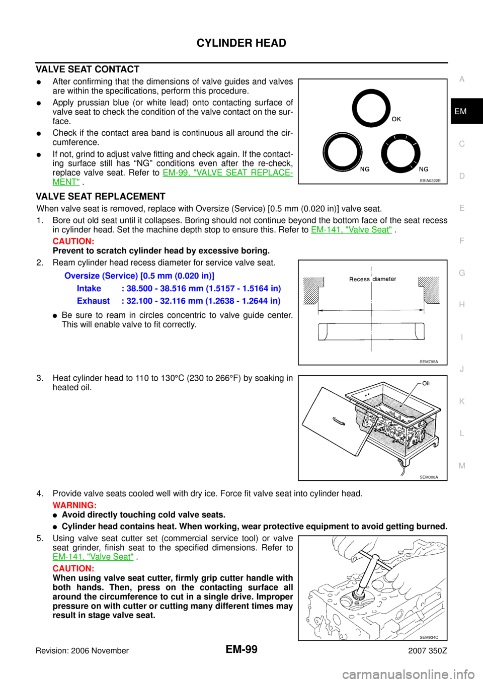
VALVE SEAT CONTACT
�After confirming that the dimensions of valve guides and valves
are within the specifications, perform this procedure.
�Apply prussian blue (or white lead) onto contacting surface of
valve seat to check the condition of the valve contact on the sur-
face.
�Check if the contact area band is continuous all around the cir-
cumference.
�If not, grind to adjust valve fitting and check again. If the contact-
ing surface still has “NG” conditions even after the re-check,
replace valve seat. Refer to EM-99, "
VALVE SEAT REPLACE-
MENT" .
VALVE SEAT REPLACEMENT
When valve seat is removed, replace with Oversize (Service) [0.5 mm (0.020 in)] valve seat.
1. Bore out old seat until it collapses. Boring should not continue beyond the bottom face of the seat recess
in cylinder head. Set the machine depth stop to ensure this. Refer to EM-141, "
Va l v e S e a t" .
CAUTION:
Prevent to scratch cylinder head by excessive boring.
2. Ream cylinder head recess diameter for service valve seat.
�Be sure to ream in circles concentric to valve guide center.
This will enable valve to fit correctly.
3. Heat cylinder head to 110 to 130°C (230 to 266°F) by soaking in
heated oil.
4. Provide valve seats cooled well with dry ice. Force fit valve seat into cylinder head.
WARNING:
�Avoid directly touching cold valve seats.
�Cylinder head contains heat. When working, wear protective equipment to avoid getting burned.
5. Using valve seat cutter set (commercial service tool) or valve
seat grinder, finish seat to the specified dimensions. Refer to
EM-141, "
Valve Seat" .
CAUTION:
When using valve seat cutter, firmly grip cutter handle with
both hands. Then, press on the contacting surface all
around the circumference to cut in a single drive. Improper
pressure on with cutter or cutting many different times may
result in stage valve seat.
SBIA0322E
Oversize (Service) [0.5 mm (0.020 in)]
Intake : 38.500 - 38.516 mm (1.5157 - 1.5164 in)
Exhaust : 32.100 - 32.116 mm (1.2638 - 1.2644 in)
SEM795A
SEM008A
SEM934C