FRONT TIMING CHAIN CASE
EM-51
C
D
E
F
G
H
I
J
K
L
MA
EM
Revision: 2006 November2007 350Z
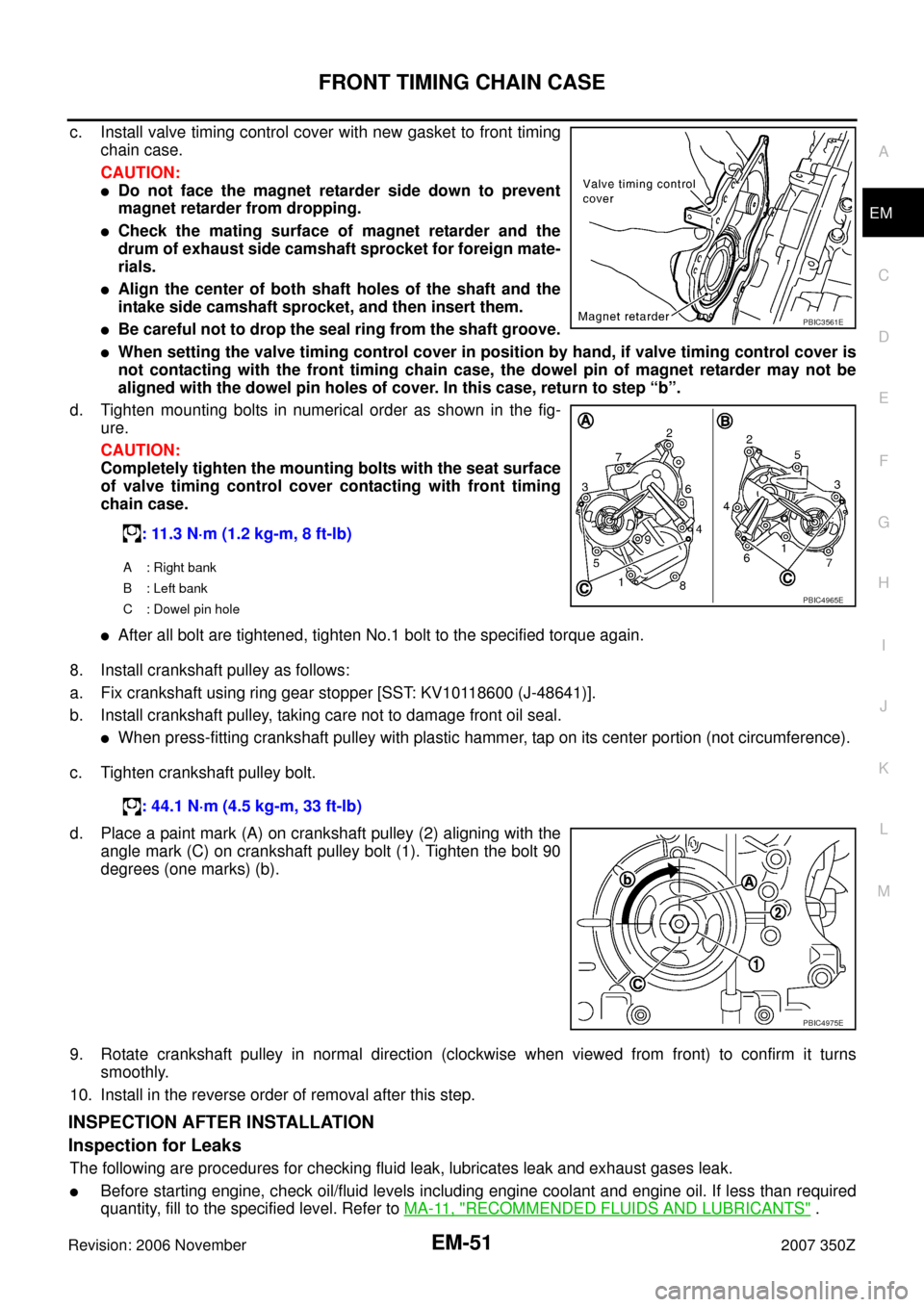
c. Install valve timing control cover with new gasket to front timing
chain case.
CAUTION:
�Do not face the magnet retarder side down to prevent
magnet retarder from dropping.
�Check the mating surface of magnet retarder and the
drum of exhaust side camshaft sprocket for foreign mate-
rials.
�Align the center of both shaft holes of the shaft and the
intake side camshaft sprocket, and then insert them.
�Be careful not to drop the seal ring from the shaft groove.
�When setting the valve timing control cover in position by hand, if valve timing control cover is
not contacting with the front timing chain case, the dowel pin of magnet retarder may not be
aligned with the dowel pin holes of cover. In this case, return to step “b”.
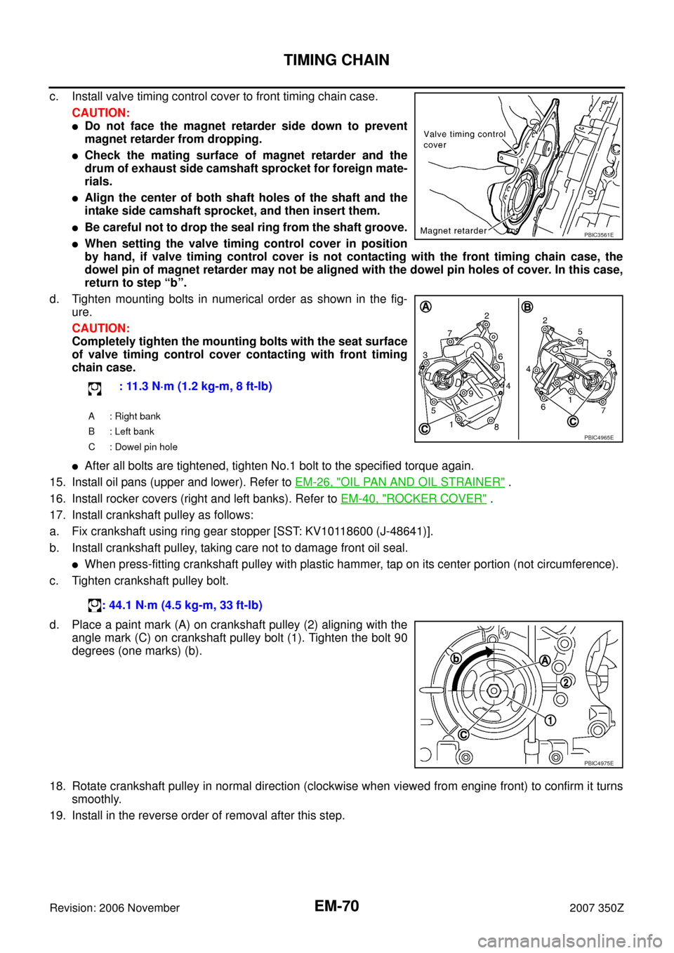
d. Tighten mounting bolts in numerical order as shown in the fig-
ure.
CAUTION:
Completely tighten the mounting bolts with the seat surface
of valve timing control cover contacting with front timing
chain case.
�After all bolt are tightened, tighten No.1 bolt to the specified torque again.
8. Install crankshaft pulley as follows:
a. Fix crankshaft using ring gear stopper [SST: KV10118600 (J-48641)].
b. Install crankshaft pulley, taking care not to damage front oil seal.
�When press-fitting crankshaft pulley with plastic hammer, tap on its center portion (not circumference).
c. Tighten crankshaft pulley bolt.
d. Place a paint mark (A) on crankshaft pulley (2) aligning with the
angle mark (C) on crankshaft pulley bolt (1). Tighten the bolt 90
degrees (one marks) (b).
9. Rotate crankshaft pulley in normal direction (clockwise when viewed from front) to confirm it turns
smoothly.
10. Install in the reverse order of removal after this step.
INSPECTION AFTER INSTALLATION
Inspection for Leaks
The following are procedures for checking fluid leak, lubricates leak and exhaust gases leak.
�Before starting engine, check oil/fluid levels including engine coolant and engine oil. If less than required
quantity, fill to the specified level. Refer to MA-11, "
RECOMMENDED FLUIDS AND LUBRICANTS" . : 11.3 N·m (1.2 kg-m, 8 ft-lb)
A : Right bank
B : Left bank
C : Dowel pin hole
PBIC3561E
PBIC4965E
: 44.1 N·m (4.5 kg-m, 33 ft-lb)
PBIC4975E
EM-70
TIMING CHAIN
Revision: 2006 November2007 350Z
c. Install valve timing control cover to front timing chain case.
CAUTION:
�Do not face the magnet retarder side down to prevent
magnet retarder from dropping.
�Check the mating surface of magnet retarder and the
drum of exhaust side camshaft sprocket for foreign mate-
rials.
�Align the center of both shaft holes of the shaft and the
intake side camshaft sprocket, and then insert them.
�Be careful not to drop the seal ring from the shaft groove.
�When setting the valve timing control cover in position
by hand, if valve timing control cover is not contacting with the front timing chain case, the
dowel pin of magnet retarder may not be aligned with the dowel pin holes of cover. In this case,
return to step “b”.
d. Tighten mounting bolts in numerical order as shown in the fig-
ure.
CAUTION:
Completely tighten the mounting bolts with the seat surface
of valve timing control cover contacting with front timing
chain case.
�After all bolts are tightened, tighten No.1 bolt to the specified torque again.
15. Install oil pans (upper and lower). Refer to EM-26, "
OIL PAN AND OIL STRAINER" .
16. Install rocker covers (right and left banks). Refer to EM-40, "
ROCKER COVER" .
17. Install crankshaft pulley as follows:
a. Fix crankshaft using ring gear stopper [SST: KV10118600 (J-48641)].
b. Install crankshaft pulley, taking care not to damage front oil seal.
�When press-fitting crankshaft pulley with plastic hammer, tap on its center portion (not circumference).
c. Tighten crankshaft pulley bolt.
d. Place a paint mark (A) on crankshaft pulley (2) aligning with the
angle mark (C) on crankshaft pulley bolt (1). Tighten the bolt 90
degrees (one marks) (b).
18. Rotate crankshaft pulley in normal direction (clockwise when viewed from engine front) to confirm it turns
smoothly.
19. Install in the reverse order of removal after this step.: 11.3 N·m (1.2 kg-m, 8 ft-lb)
A : Right bank
B : Left bank
C : Dowel pin hole
: 44.1 N·m (4.5 kg-m, 33 ft-lb)
PBIC3561E
PBIC4965E
PBIC4975E