Page 17 of 148
INTAKE MANIFOLD COLLECTOR
EM-17
C
D
E
F
G
H
I
J
K
L
MA
EM
Revision: 2006 November2007 350Z
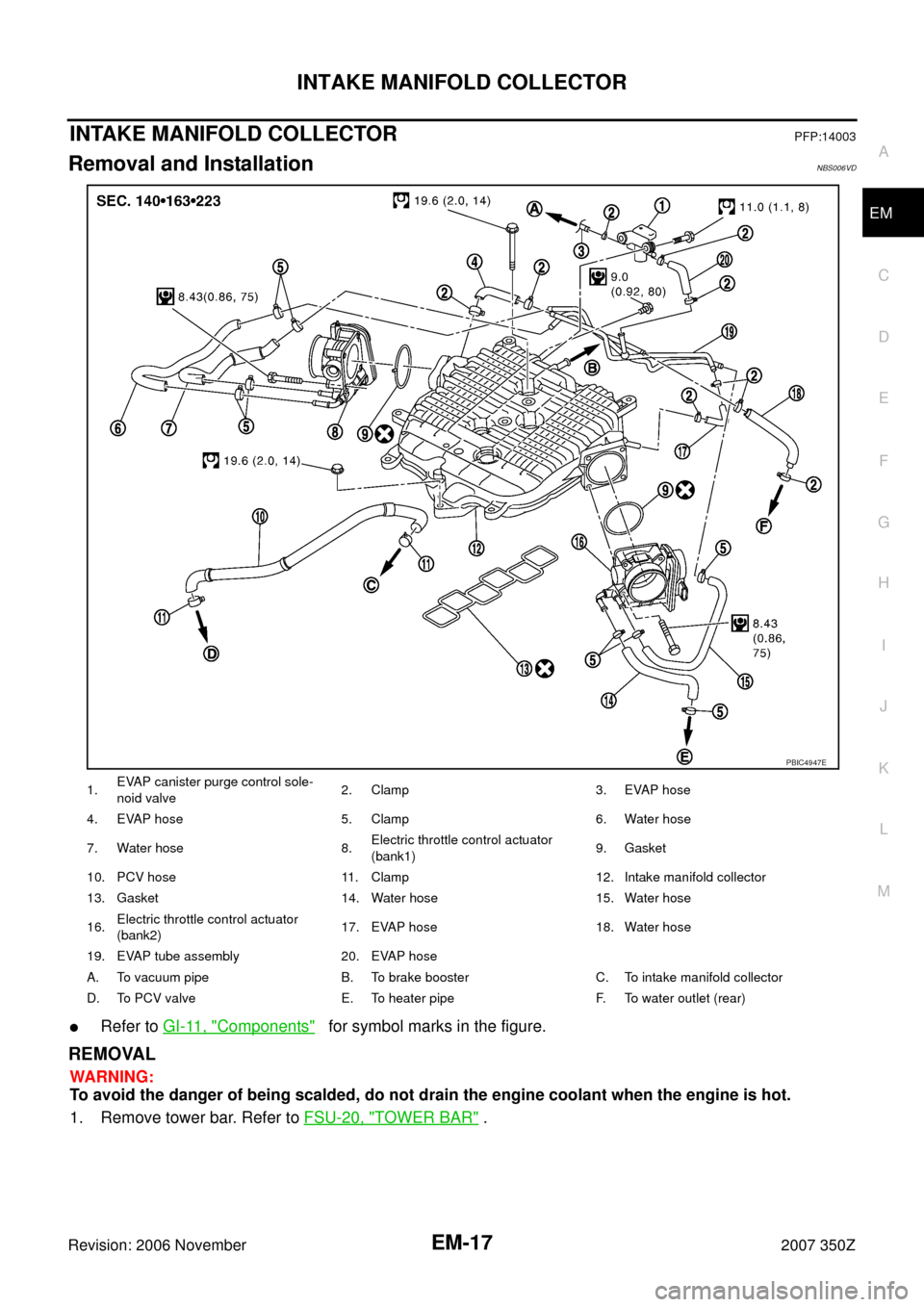
INTAKE MANIFOLD COLLECTORPFP:14003
Removal and InstallationNBS006VD
�Refer to GI-11, "Components" for symbol marks in the figure.
REMOVAL
WARNING:
To avoid the danger of being scalded, do not drain the engine coolant when the engine is hot.
1. Remove tower bar. Refer to FSU-20, "
TOWER BAR" .
1.EVAP canister purge control sole-
noid valve2. Clamp 3. EVAP hose
4. EVAP hose 5. Clamp 6. Water hose
7. Water hose 8.Electric throttle control actuator
(bank1)9. Gasket
10. PCV hose 11. Clamp 12. Intake manifold collector
13. Gasket 14. Water hose 15. Water hose
16.Electric throttle control actuator
(bank2)17. EVAP hose 18. Water hose
19. EVAP tube assembly 20. EVAP hose
A. To vacuum pipe B. To brake booster C. To intake manifold collector
D. To PCV valve E. To heater pipe F. To water outlet (rear)
PBIC4947E
Page 18 of 148
 (2) with power tool.
3. Remove air cleaner case and air duct (RH, LH). Refer to EM-15, \"
AIR CLEANER AND AIR")
EM-18
INTAKE MANIFOLD COLLECTOR
Revision: 2006 November2007 350Z
2. Remove engine cover (1) (2) with power tool.
3. Remove air cleaner case and air duct (RH, LH). Refer to EM-15, "
AIR CLEANER AND AIR DUCT" .
4. Remove electric throttle control actuator (bank1, bank2) as follows:
NOTE:
When removing only intake manifold collector, move electric throttle control actuator without disconnect-
ing water hose.
a. Drain engine coolant.
CAUTION:
Perform this step when engine is cold.
b. Disconnect water hoses from electric throttle control actuator. When engine coolant is not drained from
radiator, attach plug to water hoses to prevent engine coolant leakage.
CAUTION:
Do not spill engine coolant on drive belt.
c. Disconnect harness connector.
d. Loosen mounting bolts in reverse order as shown in the figure.
CAUTION:
�Handle carefully to avoid any shock to electric throttle
control actuator.
�Do not disassemble.
NOTE:
�Figure shows electric throttle control actuator (bank1) viewed
from the air duct side.
�Viewed from the air duct side, order of loosening mounting
bolts of electric throttle control actuator (bank2) is the same
as that of the electric throttle control actuator (bank1).
5. Disconnect vacuum hose, PCV hose and EVAP hose from intake manifold collector.
6. Remove EVAP canister purge volume control solenoid valve and EVAP tube assembly from intake mani-
fold collector.
PBIC4987E
PBIC4948E
Page 19 of 148

INTAKE MANIFOLD COLLECTOR
EM-19
C
D
E
F
G
H
I
J
K
L
MA
EM
Revision: 2006 November2007 350Z
7. Loosen mounting bolts with power tool in reverse order as
shown in the figure to remove intake manifold collector.
CAUTION:
Cover engine openings to avoid entry of foreign materials.
8. Remove PCV hose [between intake manifold collector and rocker cover (right bank)].
INSTALLATION
Note the following, and install in the reverse order of removal.
Intake Manifold Collector
If stud bolts were removed, install them and tighten to the specified torque below.
�Tighten mounting bolts in numerical order as shown in the fig-
ure.
NOTE:
Tighten mounting bolts to secure gasket and intake manifold col-
lector.
Water Hose
�Insert hose by 27 to 32 mm (1.06 to 1.26 in) from connector end.
�Clamp hose at location of 3 to 7 mm (0.12 to 0.28 in) from hose end.
Electric Throttle Control Actuator
�Install in the reverse order of removal.
�Tighten mounting bolts in numerical order as shown in the fig-
ure.
CAUTION:
�Handle carefully to avoid any shock to electric throttle
control actuator.
�Do not disassemble.
�The figure shows the electric throttle control actuator
(bank1) viewed from the air duct side.
�Viewed from the air duct side, order of tightening mount-
ing bolts of electric throttle control actuator (bank2) is
the same as that of the electric throttle control actuator
(bank1).
�Perform the “Throttle Valve Closed Position Learning” when harness connector of electric throttle control
actuator is disconnected. Refer to EC-77, "
Throttle Valve Closed Position Learning" .
�Perform the “Idle Air Volume Learning” and “Throttle Valve Closed Position Learning” when electric throt-
tle control actuator is replaced. Refer to EC-77, "
Idle Air Volume Learning" .
: Engine front
PBIC4949E
: 10.8 N·m (1.1 kg-m, 8 ft-lb)
: Engine front
PBIC4949E
PBIC4948E
Page 40 of 148

EM-40
ROCKER COVER
Revision: 2006 November2007 350Z
ROCKER COVERPFP:13264
Removal and InstallationNBS0000P
�Refer to GI-11, "Components" for symbol marks in the figure.
REMOVAL
1. Remove engine cover. Refer to EM-17, "INTAKE MANIFOLD COLLECTOR" .
2. Remove intake manifold collector. Refer to EM-17, "
INTAKE MANIFOLD COLLECTOR" .
3. Separate engine harness removing their brackets from rocker covers.
4. Remove ignition coil. Refer to EM-31, "
IGNITION COIL" .
1. PCV hose 2. Clamp 3. Ignition coil
4. Spark plug 5. PCV valve 6. O-ring
7. Rocker cover gasket (right bank) 8. Rocker cover (right bank) 9. O-ring
10. Camshaft position sensor (bank 1) 11.Exhaust valve timing control posi-
tion sensor (bank 1)12. Camshaft position sensor (bank 2)
13.Exhaust valve timing control position
sensor (bank 2)14. Rocker cover gasket (left bank) 15. Rocker cover (left bank)
16. PCV hose 17. Oil catcher 18. Oil filler cap
19. PCV hose
A. To intake manifold collector B. Refer to EM-40
C. Camshaft bracket side
D. To air duct
PBIC4964E
Page 41 of 148
ROCKER COVER
EM-41
C
D
E
F
G
H
I
J
K
L
MA
EM
Revision: 2006 November2007 350Z
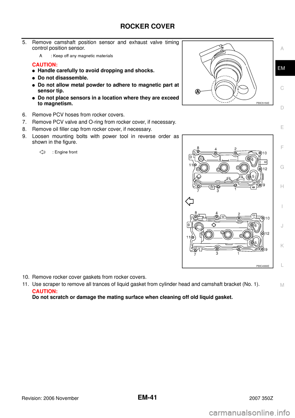
5. Remove camshaft position sensor and exhaust valve timing
control position sensor.
CAUTION:
�Handle carefully to avoid dropping and shocks.
�Do not disassemble.
�Do not allow metal powder to adhere to magnetic part at
sensor tip.
�Do not place sensors in a location where they are exceed
to magnetism.
6. Remove PCV hoses from rocker covers.
7. Remove PCV valve and O-ring from rocker cover, if necessary.
8. Remove oil filler cap from rocker cover, if necessary.
9. Loosen mounting bolts with power tool in reverse order as
shown in the figure.
10. Remove rocker cover gaskets from rocker covers.
11. Use scraper to remove all trances of liquid gasket from cylinder head and camshaft bracket (No. 1).
CAUTION:
Do not scratch or damage the mating surface when cleaning off old liquid gasket.
A : Keep off any magnetic materials
PBIC5150E
: Engine front
PBIC4990E
Page 42 of 148
![NISSAN 350Z 2007 Z33 Engine Mechanical Workshop Manual EM-42
ROCKER COVER
Revision: 2006 November2007 350Z
INSTALLATION
1. Apply liquid gasket with tube presser [SST: WS39930000 ( —
)] to joint part among rocker cover, cylinder head and cam-
shaft brack](/manual-img/5/765/w960_765-41.png "NISSAN 350Z 2007 Z33 Engine Mechanical Workshop Manual EM-42
ROCKER COVER
Revision: 2006 November2007 350Z
INSTALLATION
1. Apply liquid gasket with tube presser [SST: WS39930000 ( —
)] to joint part among rocker cover, cylinder head and cam-
shaft brack")
EM-42
ROCKER COVER
Revision: 2006 November2007 350Z
INSTALLATION
1. Apply liquid gasket with tube presser [SST: WS39930000 ( —
)] to joint part among rocker cover, cylinder head and cam-
shaft bracket (No. 1) as follows:
Use Genuine RTV Silicone Sealant or equivalent. Refer to
GI-45, "
RECOMMENDED CHEMICAL PRODUCTS AND
SEALANTS" .
NOTE:
The figure shows an example of left bank side [zoomed in
shows camshaft bracket (No. 1)].
a. Refer to the figure “a” to apply liquid gasket to joint part of cam-
shaft bracket (No. 1) and cylinder head.
b. Refer to the figure “b” to apply liquid gasket to the figure “a”
squarely.
2. Install new rocker cover gasket to rocker cover.
3. Install rocker cover.
�Check if rocker cover gasket is not dropped from installation groove of rocker cover.
4. Tighten bolts in two steps separately in numerical order as
shown in the figure.
5. Install oil filler cap to rocker cover (left bank), if removed.
6. Install new O-ring and PCV valve to rocker cover (right bank), if removed.
7. Install PCV hose.
�Insert PCV hose by 25 to 30 mm (0.98 to 1.18 in) from connector end.
�When installing, be careful not to twist or come in contact with other parts.
PBIC2474E
: Engine front
1st step
: 2.0 N·m (0.2 kg-m, 18 in-lb)
2nd step
: 8.3 N·m (0.85 kg-m, 73 in-lb)
PBIC4990E