Page 97 of 148

CYLINDER HEAD
EM-97
C
D
E
F
G
H
I
J
K
L
MA
EM
Revision: 2006 November2007 350Z
VALVE GUIDE CLEARANCE
Valve Stem Diameter
Measure diameter of valve stem with micrometer.
Valve Guide Inner Diameter
Measure inner diameter of valve guide with inside micrometer.
Valve Guide Clearance
(Valve guide clearance) = (Valve guide inner diameter) – (Valve stem diameter)
�If it exceeds the limit, replace valve and/or valve guide. When valve guide must be replaced, refer to EM-
97, "VALVE GUIDE REPLACEMENT" .
VALVE GUIDE REPLACEMENT
When valve guide is removed, replace with Oversize (Service) [0.2 mm (0.008 in)] valve guide.
1. To remove valve guide, heat cylinder head to 110 to 130°C (230
to 266°F) by soaking in heated oil.
2. Drive out valve guide with a press [under a 20 kN (2 ton, 2.2 US
ton, 2.0 lmp ton) pressure] or hammer and suitable tool.
WARNING:
Cylinder head contains heat. When working, wear protec-
tive equipment to avoid getting burned.Standard
Intake : 5.965 - 5.980 mm (0.2348 - 0.2354 in)
Exhaust : 5.962 - 5.970 mm (0.2347 - 0.2350 in)
SEM938C
Standard
Intake and Exhaust : 6.000 - 6.018 mm (0.2362 - 0.2369 in)
Valve guide clearance:
Standard
Intake : 0.020 - 0.053 mm (0.0008 - 0.0021 in)
Exhaust : 0.030 - 0.056 mm (0.0012 - 0.0022 in)
Limit
Intake : 0.08 mm (0.0031 in)
Exhaust : 0.09 mm (0.0035 in)
SEM008A
SEM931C
Page 98 of 148
EM-98
CYLINDER HEAD
Revision: 2006 November2007 350Z
3. Using valve guide reamer (commercial service tool), ream cylin-
der head valve guide hole.
4. Heat cylinder head to 110 to 130°C (230 to 266°F) by soaking in
heated oil.
5. Using valve guide drift (commercial service tool), press valve
guide from camshaft side to the dimensions as in the figure.
WARNING:
Cylinder head contains heat. When working, wear protec-
tive equipment to avoid getting burned.
6. Using valve guide reamer (commercial service tool), apply
reamer finish to valve guide.Valve guide hole diameter (for service parts):
Intake and exhaust
: 10.175 - 10.196 mm (0.4006 - 0.4014 in)
SEM932C
SEM008A
Projection “L”
Intake and exhaust
: 12.6 - 12.8 mm (0.496 - 0.504 in)
SEM950E
Standard:
Intake and exhaust
: 6.000 - 6.018 mm (0.2362 - 0.2369 in)
SEM932C
Page 99 of 148

CYLINDER HEAD
EM-99
C
D
E
F
G
H
I
J
K
L
MA
EM
Revision: 2006 November2007 350Z
VALVE SEAT CONTACT
�After confirming that the dimensions of valve guides and valves
are within the specifications, perform this procedure.
�Apply prussian blue (or white lead) onto contacting surface of
valve seat to check the condition of the valve contact on the sur-
face.
�Check if the contact area band is continuous all around the cir-
cumference.
�If not, grind to adjust valve fitting and check again. If the contact-
ing surface still has “NG” conditions even after the re-check,
replace valve seat. Refer to EM-99, "
VALVE SEAT REPLACE-
MENT" .
VALVE SEAT REPLACEMENT
When valve seat is removed, replace with Oversize (Service) [0.5 mm (0.020 in)] valve seat.
1. Bore out old seat until it collapses. Boring should not continue beyond the bottom face of the seat recess
in cylinder head. Set the machine depth stop to ensure this. Refer to EM-141, "
Va l v e S e a t" .
CAUTION:
Prevent to scratch cylinder head by excessive boring.
2. Ream cylinder head recess diameter for service valve seat.
�Be sure to ream in circles concentric to valve guide center.
This will enable valve to fit correctly.
3. Heat cylinder head to 110 to 130°C (230 to 266°F) by soaking in
heated oil.
4. Provide valve seats cooled well with dry ice. Force fit valve seat into cylinder head.
WARNING:
�Avoid directly touching cold valve seats.
�Cylinder head contains heat. When working, wear protective equipment to avoid getting burned.
5. Using valve seat cutter set (commercial service tool) or valve
seat grinder, finish seat to the specified dimensions. Refer to
EM-141, "
Valve Seat" .
CAUTION:
When using valve seat cutter, firmly grip cutter handle with
both hands. Then, press on the contacting surface all
around the circumference to cut in a single drive. Improper
pressure on with cutter or cutting many different times may
result in stage valve seat.
SBIA0322E
Oversize (Service) [0.5 mm (0.020 in)]
Intake : 38.500 - 38.516 mm (1.5157 - 1.5164 in)
Exhaust : 32.100 - 32.116 mm (1.2638 - 1.2644 in)
SEM795A
SEM008A
SEM934C
Page 100 of 148
EM-100
CYLINDER HEAD
Revision: 2006 November2007 350Z
6. Using compound, grind to adjust valve fitting.
7. Check again for normal contact. Refer to EM-99, "
VALVE SEAT CONTACT" .
VALVE SPRING SQUARENESS
�Set try square along the side of valve spring and rotate spring.
Measure the maximum clearance between the top face of spring
and try square.
�If it exceeds the limit, replace valve spring.
VALVE SPRING DIMENSIONS AND VALVE SPRING PRESSURE LOAD
�Check valve spring pressure at specified spring height.
�If the installation load or load with valve open is out of the standard, replace valve spring.Limit: : 1.9 mm (0.075 in)
PBIC0080E
Standard:
Intake and exhaust
Free height : 43.85 mm (1.7264 in)
Installation height : 37.0 mm (1.457 in)
Installation load : 166 – 188 N
(16.9 – 19.2 kg, 37 – 42 lb)
Height during valve open : 26.8 mm (1.055 in)
Load with valve open : 502 – 566 N
(51.2 – 57.7 kg, 113 – 127 lb)
SEM113
Page 101 of 148

ENGINE ASSEMBLY
EM-101
C
D
E
F
G
H
I
J
K
L
MA
EM
Revision: 2006 November2007 350Z
ENGINE ASSEMBLYPFP:10001
Removal and InstallationNBS00012
WARNING:
�Situate vehicle on a flat and solid surface.
�Place chocks at front and back of rear wheels.
�For engines not equipped with engine slingers, attach proper slingers and bolts described in
PARTS CATALOG.
CAUTION:
�Always be careful to work safely, avoid forceful or uninstructed operations.
�Do not start working until exhaust system and engine coolant are cool enough.
�If items or work required are not covered by the engine section, refer to the applicable sections.
�Always use the support point specified for lifting.
�Use either 2-pole lift type or separate type lift as best you can. If board-on type is used for
unavoidable reasons, support at the rear axle jacking point with transmission jack or similar tool
before starting work, in preparation for the backward shift of center of gravity.
�For supporting points for lifting and jacking point at rear axle, refer to GI-39, "Garage Jack and
Safety Stand" .
1. Engine mounting bracket (RH) 2. Heat insulator (RH) 3. Engine mounting Insulator (RH)
4. Engine mounting insulator (LH) 5. Heat insulator (LH) 6. Engine mounting bracket (LH)
7. Harness bracket 8. Rear engine mounting member 9. Mass damper
10. Engine mounting insulator (rear) 11. Dynamic damper
PBIC2309E
Page 102 of 148

EM-102
ENGINE ASSEMBLY
Revision: 2006 November2007 350Z
REMOVAL
Outline
At first, remove engine and transmission assembly with front suspension member from vehicle downward.
Then separate engine from transmission.
Preparation
1. Release fuel pressure. Refer to EC-79, "FUEL PRESSURE RELEASE" .
2. Drain engine coolant from radiator. Refer to CO-10, "
Changing Engine Coolant" .
CAUTION:
�Perform this step when engine is cold.
�Do not spill engine coolant on drive belts.
3. Disconnect both battery cables. Refer to SC-4, "
BATTERY" .
4. Remove the following parts:
�Tower bar: Refer to FSU-20, "TOWER BAR" .
�Engine cover: Refer to EM-17, "INTAKE MANIFOLD COLLECTOR" .
�Cowl top cover (RH): Refer to EI-20, "COWL TOP" .
�Undercover
�Drive belts: Refer to EM-12, "DRIVE BELTS" .
�Front road wheels and tires
5. Remove air cleaner case and air duct. Refer to EM-15, "
AIR CLEANER AND AIR DUCT" .
6. Discharge refrigerant from A/C circuit. Refer to ATC-123, "
REFRIGERANT LINES" .
7. Remove radiator cooling fan assembly, reservoir tank and hoses. Refer to CO-21, "
COOLING FAN" and
CO-13, "
RADIATOR" .
Engine Room
1. Disconnect heater hose at engine-side, and fit a plug onto hose end to prevent engine coolant leak.
2. Disconnect ground cable (between vehicle to left cylinder head).
3. Disconnect battery positive cable harness at vehicle side and temporarily fasten it on engine.
4. Disconnect A/C piping from A/C compressor, and temporarily fasten it on vehicle with a rope.
5. Remove engine room harness connectors as shown in the fig-
ure.
6. Disconnect two body ground cables.
7. Disconnect brake booster vacuum hose.
8. Disconnect fuel feed hose (with damper) and EVAP hose. Refer to EM-34, "
FUEL INJECTOR AND FUEL
TUBE" .
CAUTION:
Fit plugs onto disconnected hoses to prevent fuel leak.
9. Remove reservoir tank of power steering oil pump, and piping from vehicle, and temporarily secure them
on engine.
CAUTION:
When temporarily securing, keep the reservoir tank upright to avoid a fluid leak.
Passenger Room Side
Follow procedure below to disconnect engine room harness connectors at passenger room side, and tempo-
rarily secure them on engine.
PBIC1105E
Page 103 of 148

ENGINE ASSEMBLY
EM-103
C
D
E
F
G
H
I
J
K
L
MA
EM
Revision: 2006 November2007 350Z
1. Remove passenger-side kicking plate inner, dash side finisher, and instrument passenger panel lower.
Refer to EI-35, "
BODY SIDE TRIM" and IP-10, "INSTRUMENT PANEL ASSEMBLY" .
2. Disconnect engine room harness connectors at unit sides TCM
(A/T models), ECM and other.
3. Disengage intermediate fixing point. Pull out engine room harnesses to engine room side, and temporarily
secure them on engine.
CAUTION:
�When pulling out harnesses, take care not to damage harnesses and connectors.
�After temporarily securing, cover connectors with vinyl or similar material to protect against for-
eign material adhesion.
Vehicle Underbody
1. Remove exhaust front tube. Refer to EX-3, "EXHAUST SYSTEM" .
2. Disconnect steering lower joint at power steering gear assembly side, and release steering lower shaft.
Refer to PS-10, "
STEERING COLUMN" .
3. Remove propeller shaft. Refer to PR-5, "
REAR PROPELLER SHAFT" .
CAUTION:
Do not impact or damage propeller shaft tube.
4. Disengage shift lever and remove clutch tube (M/T models). Refer to MT-18, "
TRANSMISSION ASSEM-
BLY" and CL-15, "CLUTCH PIPING" .
5. Disengage A/T control rod at control device assembly side. Then, temporarily secure it on transmission,
so that it does not sag (A/T models). Refer to AT- 2 0 4 , "
SHIFT CONTROL SYSTEM" .
6. Remove rear plate cover from oil pan (upper). Then remove bolts fixing drive plate to torque converter
(A/T models). Refer to EM-26, "
OIL PAN AND OIL STRAINER" and AT- 2 4 2 , "TRANSMISSION ASSEM-
BLY" .
7. Remove bolts fixing transmission to lower rear side of oil pan (upper). Refer to MT-18, "
TRANSMISSION
ASSEMBLY" (M/T models) or AT- 2 4 2 , "TRANSMISSION ASSEMBLY" (A/T models).
8. Remove front stabilizer. Refer to FSU-18, "
STABILIZER BAR" .
9. Separate steering outer sockets from steering knuckle. Refer to PS-17, "
POWER STEERING GEAR AND
LINKAGE" .
10. Separate transverse links from suspension member and vehicle body. Refer to FSU-13, "
TRANSVERSE
LINK" .
Removal Work
1. Use a manual lift table caddy (commercial service tool) or equiv-
alently rigid tool such as transmission jack. Securely support
bottom of suspension member and transmission.
CAUTION:
Put a piece of wood or something similar as the supporting
surface, secure a completely stable condition.
2. Remove front cross bar. Refer to FSU-5, "
FRONT SUSPENSION ASSEMBLY" .
PBIC0883E
PBIC0804E
Page 104 of 148

EM-104
ENGINE ASSEMBLY
Revision: 2006 November2007 350Z
3. Remove rear engine mounting member bolts.
4. Remove front suspension member mounting nuts. Refer to FSU-5, "
FRONT SUSPENSION ASSEMBLY" .
5. Carefully lower jack, or raise lift to remove the engine, transmission and front suspension member assem-
bly. When performing work, observe the following caution:
CAUTION:
�Confirm there is no interference with the vehicle.
�Make sure that all connection points have been disconnected.
�Keep in mind the center of the vehicle gravity changes. If necessary, use jack(s) to support the
vehicle at rear jacking point(s) to prevent it from falling it off the lift.
Separation Work
1. Install engine slingers into front of cylinder head (right bank) and
rear of cylinder head (left bank).
�To protect rocker cover against damage caused by tilting of
engine slinger, insert spacer between cylinder head and
engine rear lower slinger, in direction shown in the figure.
NOTE:
Spacer is a component part of engine rear upper slinger
assembly.
2. Remove power steering oil pump from engine side. Refer to PS-28, "
POWER STEERING OIL PUMP" .
3. Remove engine mounting insulators (RH and LH) under side nut.
4. Lift with hoist and separate engine and transmission assembly from front suspension member.
CAUTION:
�Before and during this lifting, always make sure that any harnesses are left connected.
�Avoid damage to and oil/grease smearing or spills onto engine mounting insulator.
5. Remove alternator. Refer to SC-20, "
CHARGING SYSTEM" .
6. Remove A/C compressor. Refer to ATC-125, "
Removal and Installation of Compressor" .
7. Remove starter motor. Refer to SC-8, "
STARTING SYSTEM" .
8. Separate engine from transmission. Refer to MT-18, "
TRANSMISSION ASSEMBLY" (M/T models) or AT-
242, "TRANSMISSION ASSEMBLY" (A/T models).
9. Remove engine mounting insulators (RH and LH) and brackets (RH and LH) from engine.
10. Remove rear engine mounting member and engine mounting insulator (rear) from transmission.
INSTALLATION
Note the following, and install in the reverse order of removal.
�Do not allow engine mounting insulator to be damage and careful no engine oil gets on it.
�For a location with a positioning pin, insert it securely into hole of mating part.
�For a part with a specified installation orientation, refer to component figure in EM-101, "Removal and
Installation" . Slinger bolts:
: 28.0 N·m (2.9 kg-m, 21 ft-lb)
PBIC2061E
KBIA1017E
 1
1 2
2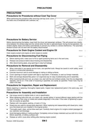 3
3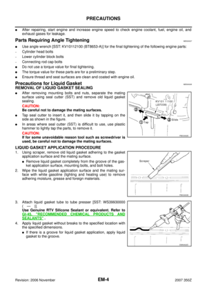 4
4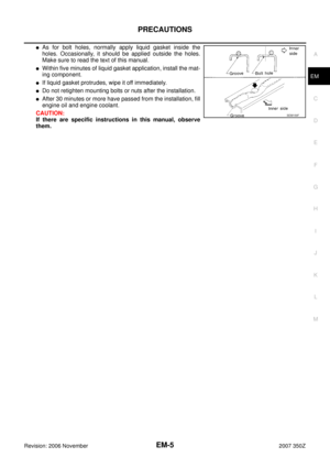 5
5 6
6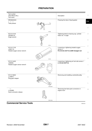 7
7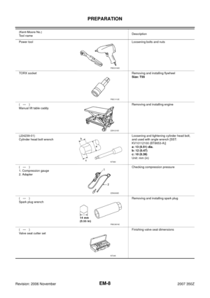 8
8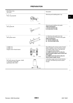 9
9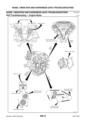 10
10 11
11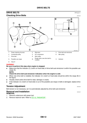 12
12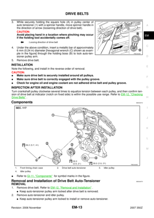 13
13 14
14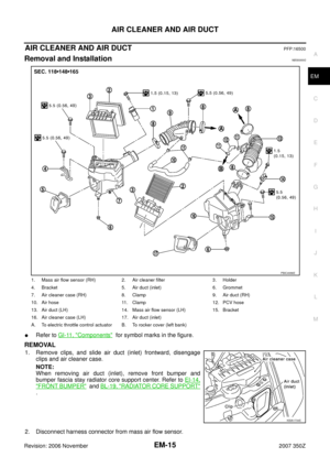 15
15 16
16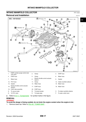 17
17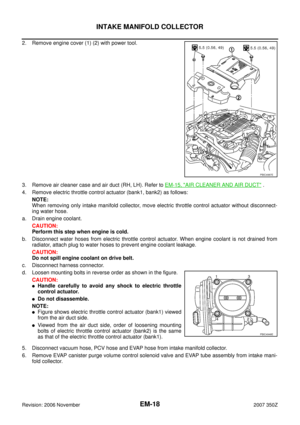 18
18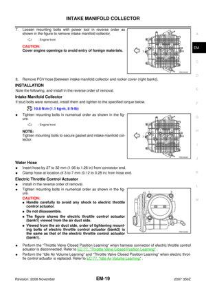 19
19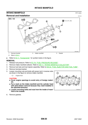 20
20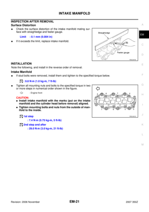 21
21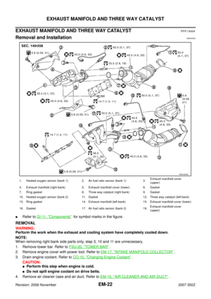 22
22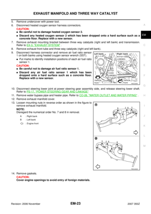 23
23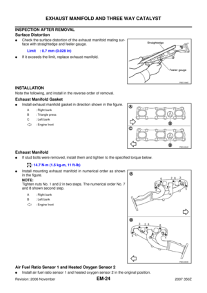 24
24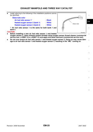 25
25 26
26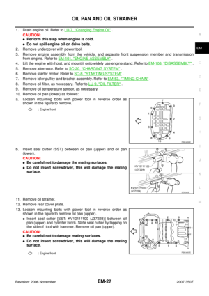 27
27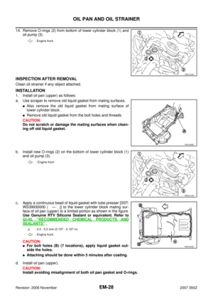 28
28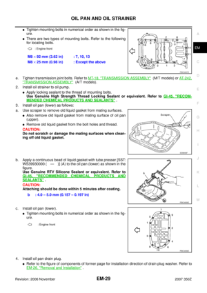 29
29 30
30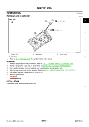 31
31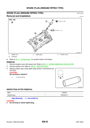 32
32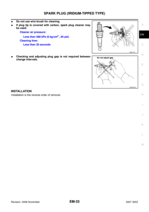 33
33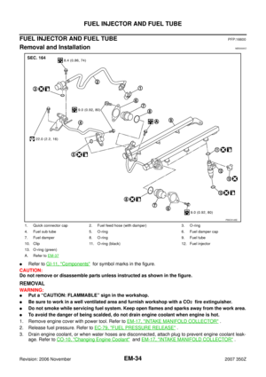 34
34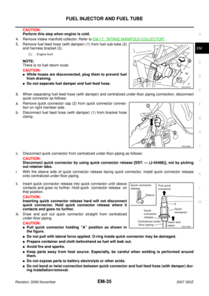 35
35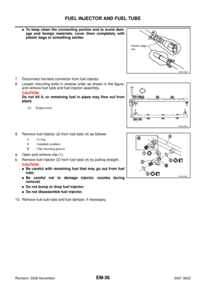 36
36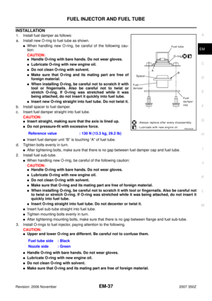 37
37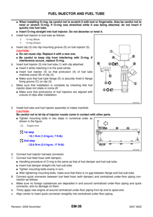 38
38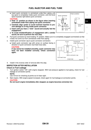 39
39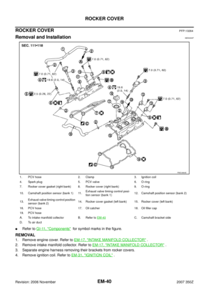 40
40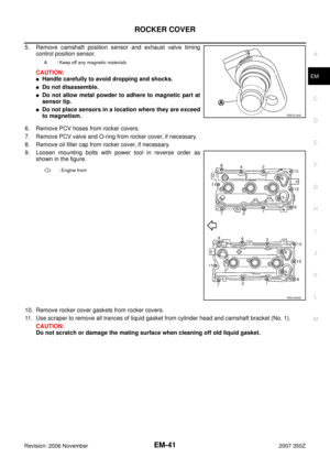 41
41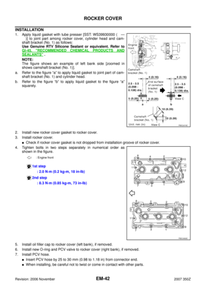 42
42 43
43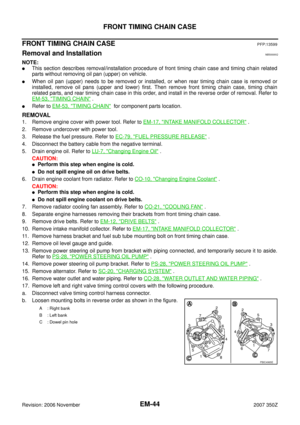 44
44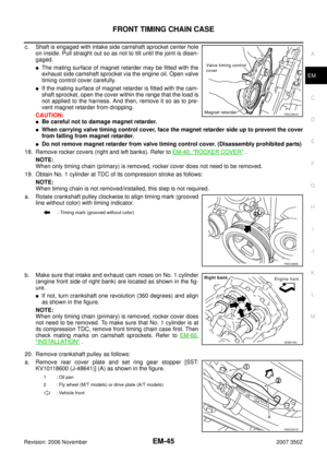 45
45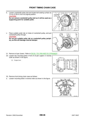 46
46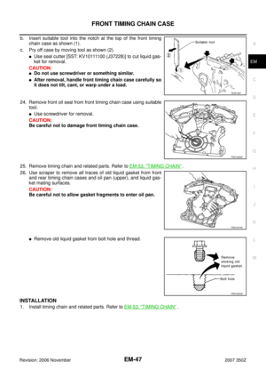 47
47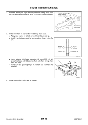 48
48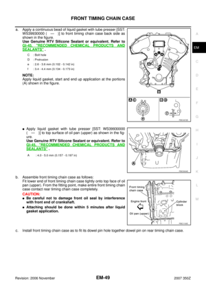 49
49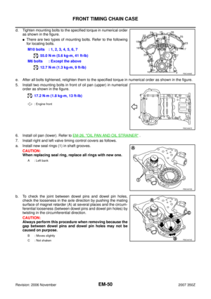 50
50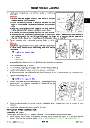 51
51 52
52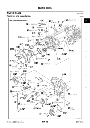 53
53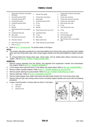 54
54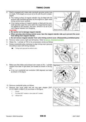 55
55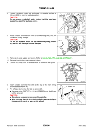 56
56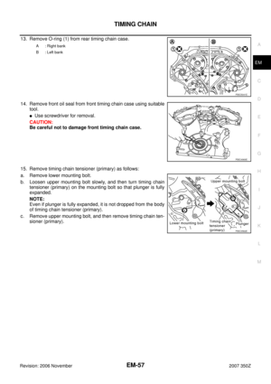 57
57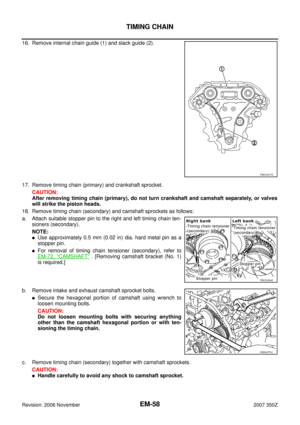 58
58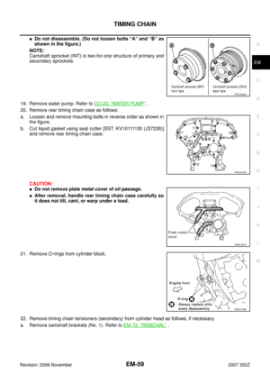 59
59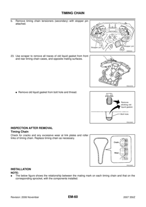 60
60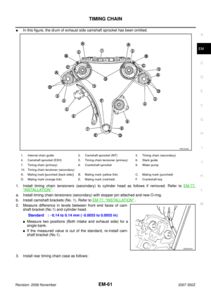 61
61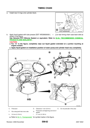 62
62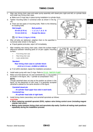 63
63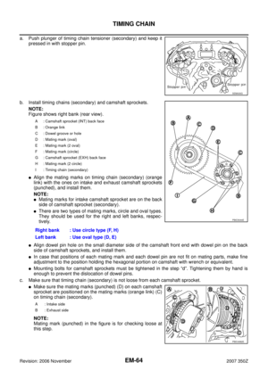 64
64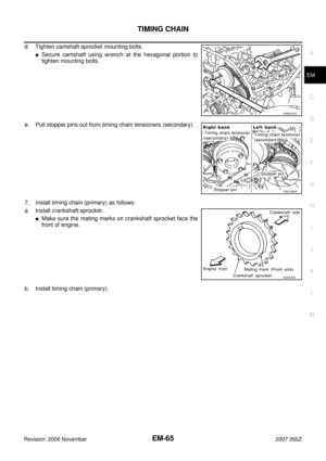 65
65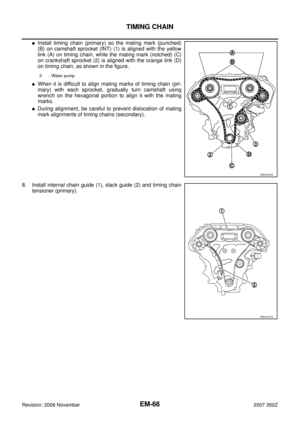 66
66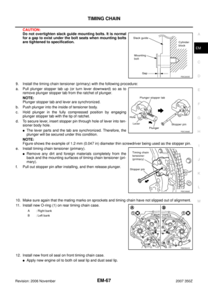 67
67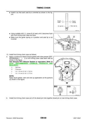 68
68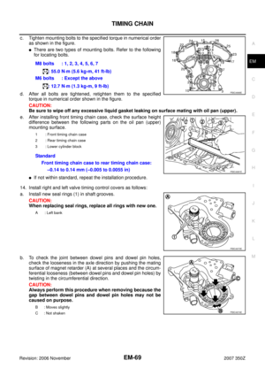 69
69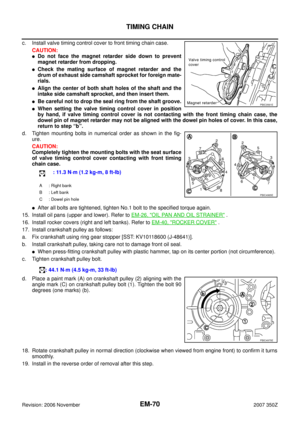 70
70 71
71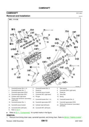 72
72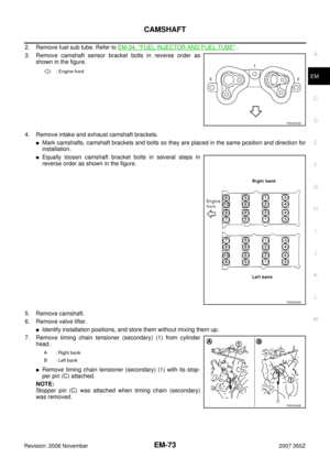 73
73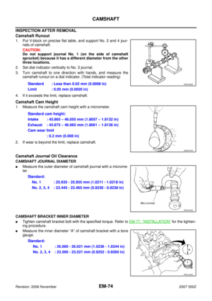 74
74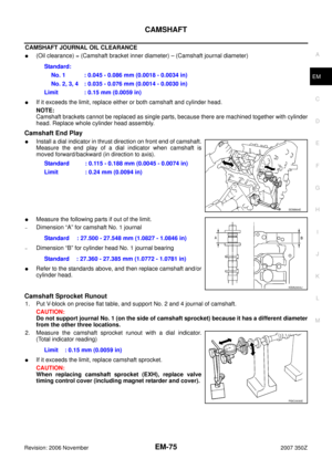 75
75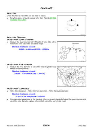 76
76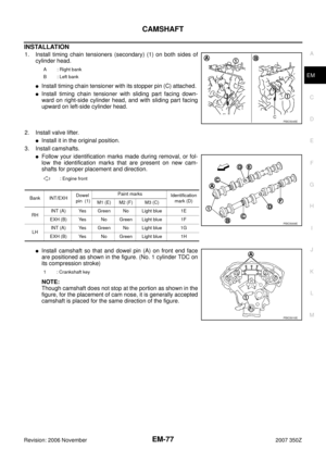 77
77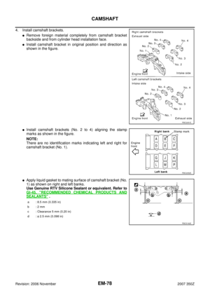 78
78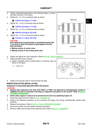 79
79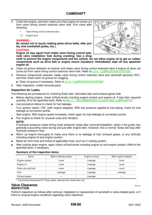 80
80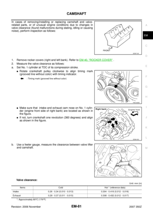 81
81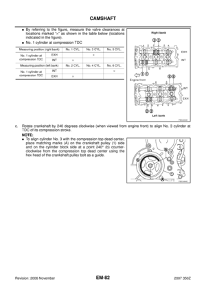 82
82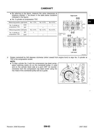 83
83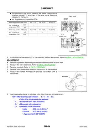 84
84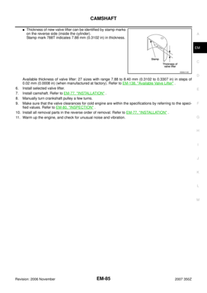 85
85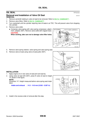 86
86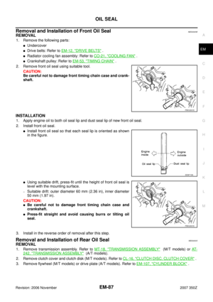 87
87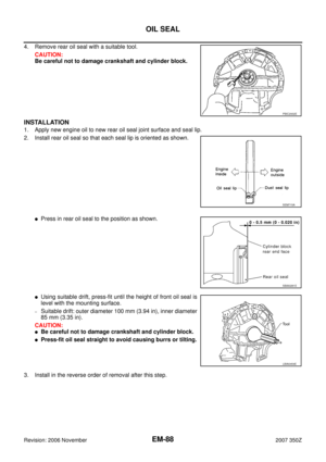 88
88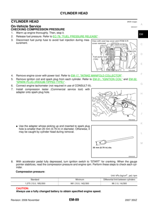 89
89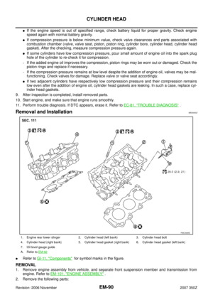 90
90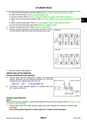 91
91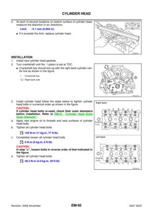 92
92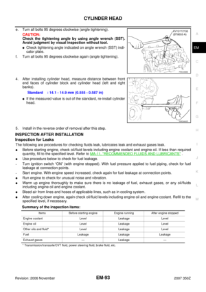 93
93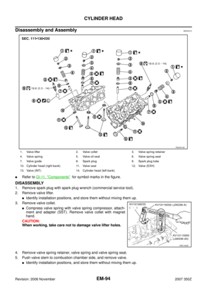 94
94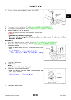 95
95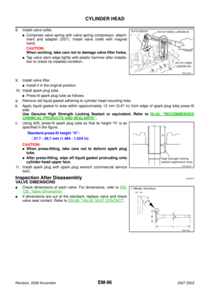 96
96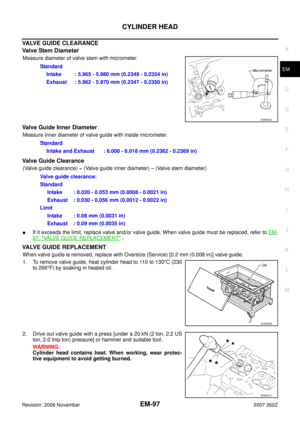 97
97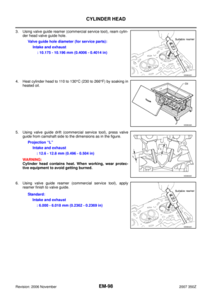 98
98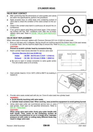 99
99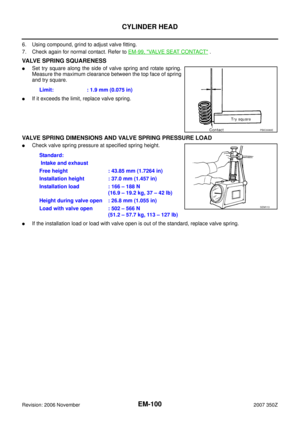 100
100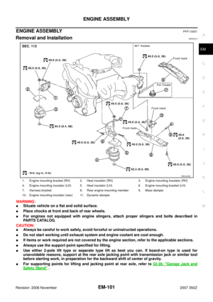 101
101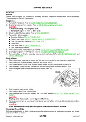 102
102 103
103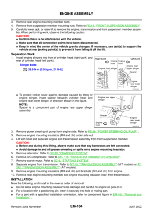 104
104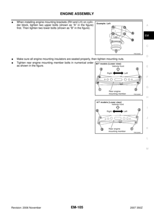 105
105 106
106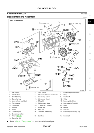 107
107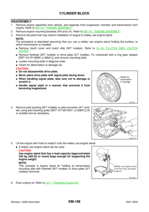 108
108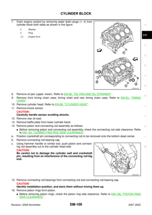 109
109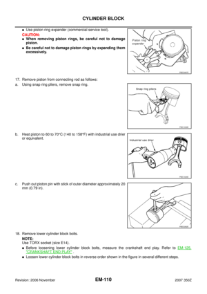 110
110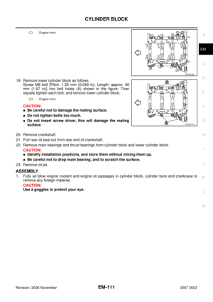 111
111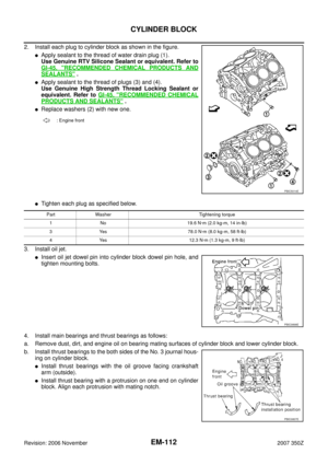 112
112 113
113 114
114 115
115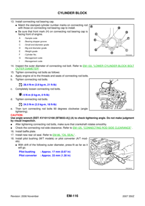 116
116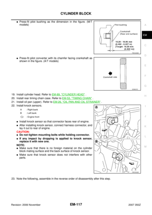 117
117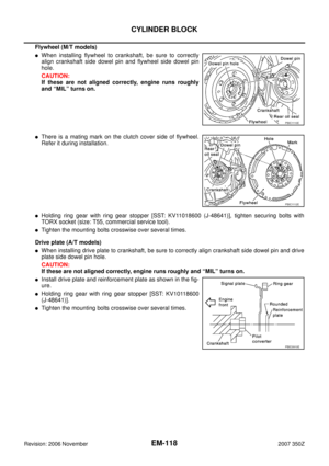 118
118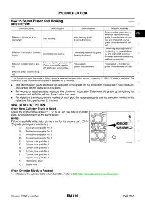 119
119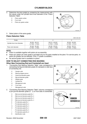 120
120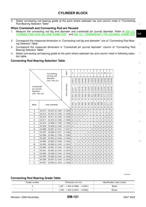 121
121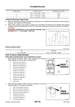 122
122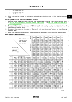 123
123 124
124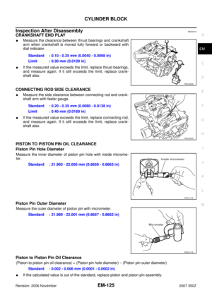 125
125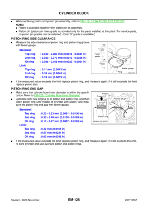 126
126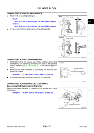 127
127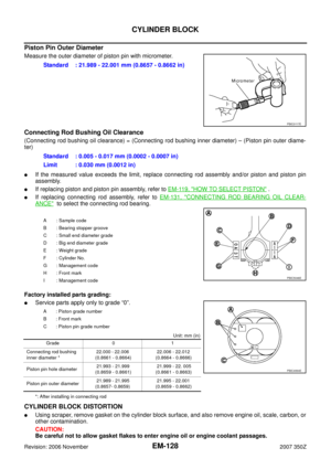 128
128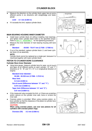 129
129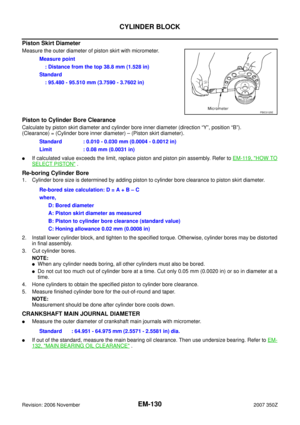 130
130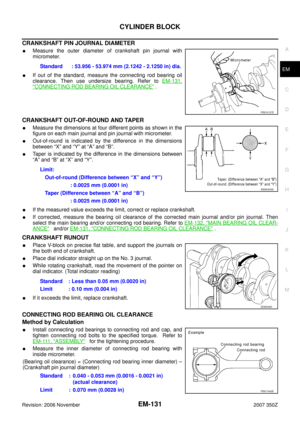 131
131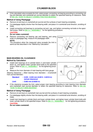 132
132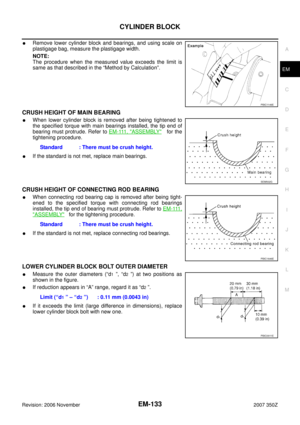 133
133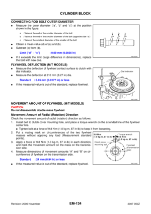 134
134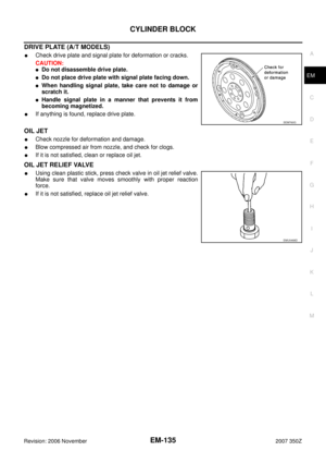 135
135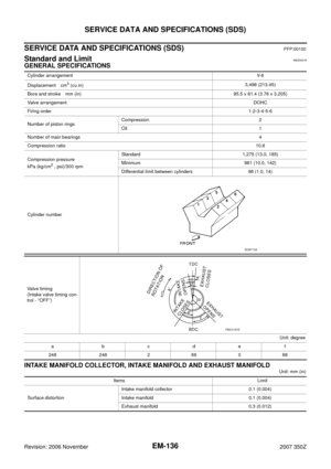 136
136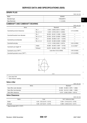 137
137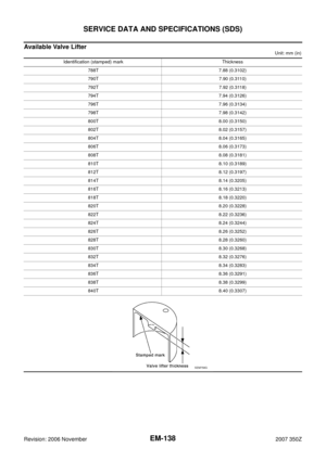 138
138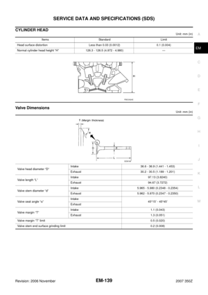 139
139 140
140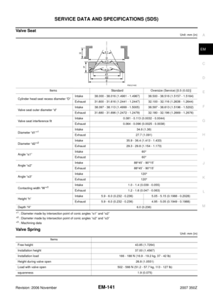 141
141 142
142 143
143 144
144 145
145 146
146 147
147, ream cylin-
der head valve guide hole.
4. Heat cylinder head to 110 to 130°C (230 to 266°F")
