Page 121 of 148

CYLINDER BLOCK
EM-121
C
D
E
F
G
H
I
J
K
L
MA
EM
Revision: 2006 November2007 350Z
3. Select connecting rod bearing grade at the point where selected row and column meet in “Connecting
Rod Bearing Selection Table”.
When Crankshaft and Connecting Rod are Reused
1. Measure the connecting rod big end diameter and crankshaft pin journal diameter. Refer to EM-127,
"CONNECTING ROD BIG END DIAMETER" . and EM-131, "CRANKSHAFT PIN JOURNAL DIAMETER"
.
2. Correspond the measured dimension in “Connecting rod big end diameter” row of “Connecting Rod Bear-
ing Selection Table”.
3. Correspond the measured dimension in “Crankshaft pin journal diameter” column of “Connecting Rod
Bearing Selection Table”.
4. Select connecting rod bearing grade at the point where selected row and column meet in following selec-
tion table.
Connecting Rod Bearing Selection Table
Connecting Rod Bearing Grade Table
PBIC5023E
Grade number Thickness mm (in) Identification color (mark)
0 1.497 – 1.500 (0.0589 – 0.0591) Black
1 1.500 – 1.503 (0.0591 – 0.0592) Brown
Page 122 of 148

EM-122
CYLINDER BLOCK
Revision: 2006 November2007 350Z
Undersize Bearings Usage Guide
�When the specified connecting rod bearing oil clearance is not obtained with standard size connecting rod
bearings, use undersize (US) bearings.
�When using undersize (US) bearing, measure the connecting rod bearing inner diameter with bearing
installed, and grind crankshaft pin so that the connecting rod bearing oil clearance satisfies the standard.
CAUTION:
In grinding crankshaft pin to use undersize bearings, keep
the fillet R [1.5 – 1.7 mm (0.059 – 0.067 in)].
Bearing undersize table
Unit: mm (in)
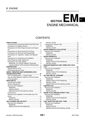
HOW TO SELECT MAIN BEARING
When New Cylinder Block and Crankshaft are Used
1. “Main Bearing Selection Table” rows correspond to bearing
housing grade on rear left side of cylinder block.
2. “Main Bearing Selection Table” columns correspond to journal
diameter grade on front side of crankshaft.
2 1.503 – 1.506 (0.0592 – 0.0593) Green
3 1.506 – 1.509 (0.0593 – 0.0594) Yellow
4 1.509 – 1.512 (0.0594 – 0.0595) Blue Grade number Thickness mm (in) Identification color (mark)
PBIC1908E
Size Thickness
US 0.25 (0.0098) 1.626 - 1.634 (0.0640 - 0.0643)
A : Bearing housing grade No. 1
B : Bearing housing grade No. 2
C : Bearing housing grade No. 3
D : Bearing housing grade No. 4
E : Cylinder bore grade No. 1
F : Cylinder bore grade No. 2
G : Cylinder bore grade No. 3
H : Cylinder bore grade No. 4
I : Cylinder bore grade No. 5
J : Cylinder bore grade No. 6
K : Identification code
: Engine front
A : Main journal diameter grade No. 1
B : Main journal diameter grade No. 2
C : Main journal diameter grade No. 3
D : Main journal diameter grade No. 4
E : Pin diameter grade No. 1
F : Pin diameter grade No. 2
G : Pin diameter grade No. 3
H : Pin diameter grade No. 4
PBIC4995E
PBIC4996E
Page 123 of 148
CYLINDER BLOCK
EM-123
C
D
E
F
G
H
I
J
K
L
MA
EM
Revision: 2006 November2007 350Z3. Select main bearing grade at the point where selected row and column meet in “Main Bearing Selection
Table”.
When Cylinder Block and Crankshaft are Reused
1. Measure cylinder block main bearing housing inner diameter and crankshaft main journal diameter. Refer
to EM-129, "
MAIN BEARING HOUSING INNER DIAMETER" and EM-130, "CRANKSHAFT MAIN
JOURNAL DIAMETER" .
2. Correspond the measured dimension in “Cylinder block main bearing housing inner diameter” row of
“Main Bearing Selection Table”.
3. Correspond the measured dimension in “Crankshaft main journal diameter” column of “Main Bearing
Selection Table”.
4. Select main bearing grade at the point where selected row and column meet in following selection table.
Main Bearing Selection Table
I : Pin diameter grade No. 5
J : Pin diameter grade No. 6
K : Identification code
PBIC5024E
Page 124 of 148

Undersize Bearing Usage Guide
�When the specified main bearing oil clearance is not obtained with standar")
EM-124
CYLINDER BLOCK
Revision: 2006 November2007 350Z
Main Bearing Grade Table (All Journals)
Undersize Bearing Usage Guide
�When the specified main bearing oil clearance is not obtained with standard size main bearings, use
underside (US) bearing.
�When using undersize (US) bearing, measure the main bearing inner diameter with bearing installed, and
grind main journal so that the main bearing oil clearance satisfies the standard.
CAUTION:
In grinding crankshaft main journal to use undersize bear-
ings, keep the fillet R [1.5 – 1.7 mm (0.059 – 0.067 in)].
Bearing undersize table
Unit: mm (in) Grade numberThickness
Unit: mm (in)Width
Unit: mm (in)Identification color Remarks
0 2.500 - 2.503 (0.0984 - 0.0985)
19.9 - 20.1
(0.783 - 0.791)Black
Grade and color are
the same for upper
and lower bearings. 1 2.503 - 2.506 (0.0985 - 0.0987) Brown
2 2.506 - 2.509 (0.0987 - 0.0988) Green
3 2.509 - 2.512 (0.0988 - 0.0989) Yellow
4 2.512 - 2.515 (0.0989 - 0.0990) Blue
5 2.515 - 2.518 (0.0990 - 0.0991) Pink
6 2.518 - 2.521 (0.0991 - 0.0993) Purple
7 2.521 - 2.524 (0.0993 - 0.0994) White
01UPR 2.503 - 2.506 (0.0985 - 0.0987) Brown
Grade and color are
different for upper and
lower bearings. LWR 2.500 - 2.503 (0.0984 - 0.0985) Black
12UPR 2.506 - 2.509 (0.0987 - 0.0988) Green
LWR 2.503 - 2.506 (0.0985 - 0.0987) Brown
23UPR 2.509 - 2.512 (0.0988 - 0.0989) Yellow
LWR 2.506 - 2.509 (0.0987 - 0.0988) Green
34UPR 2.512 - 2.515 (0.0989 - 0.0990) Blue
LWR 2.509 - 2.512 (0.0988 - 0.0989) Yellow
45UPR 2.515 - 2.518 (0.0990 - 0.0991) Pink
LWR 2.512 - 2.515 (0.0989 - 0.0990) Blue
56UPR 2.518 - 2.521 (0.0991 - 0.0993) Purple
LWR 2.515 - 2.518 (0.0990 - 0.0991) Pink
67UPR 2.521 - 2.524 (0.0993 - 0.0994) White
LWR 2.518 - 2.521 (0.0991 - 0.0993) Purple
PBIC1908E
Size Thickness
US 0.25 (0.0098) 2.633 - 2.641 (0.1037 - 0.1040)
Page 125 of 148

CYLINDER BLOCK
EM-125
C
D
E
F
G
H
I
J
K
L
MA
EM
Revision: 2006 November2007 350Z
Inspection After DisassemblyNBS00015
CRANKSHAFT END PLAY
�Measure the clearance between thrust bearings and crankshaft
arm when crankshaft is moved fully forward or backward with
dial indicator.
�If the measured value exceeds the limit, replace thrust bearings,
and measure again. If it still exceeds the limit, replace crank-
shaft also.
CONNECTING ROD SIDE CLEARANCE
�Measure the side clearance between connecting rod and crank-
shaft arm with feeler gauge.
�If the measured value exceeds the limit, replace connecting rod,
and measure again. If it still exceeds the limit, replace crank-
shaft also.
PISTON TO PISTON PIN OIL CLEARANCE
Piston Pin Hole Diameter
Measure the inner diameter of piston pin hole with inside microme-
ter.
Piston Pin Outer Diameter
Measure the outer diameter of piston pin with micrometer.
Piston to Piston Pin Oil Clearance
(Piston to piston pin oil clearance) = (Piston pin hole diameter) – (Piston pin outer diameter)
�If the calculated value is out of the standard, replace piston and piston pin assembly.Standard : 0.10 - 0.25 mm (0.0040 - 0.0098 in)
Limit : 0.30 mm (0.0120 in)
PBIC2953E
Standard : 0.20 - 0.35 mm (0.0080 - 0.0138 in)
Limit : 0.40 mm (0.0160 in)
PBIC2954E
Standard : 21.993 - 22.005 mm (0.8659 - 0.8663 in)
PBIC0116E
Standard : 21.989 - 22.001 mm (0.8657 - 0.8662 in)
PBIC0117E
Standard : 0.002 - 0.006 mm (0.0001 - 0.0002 in)
Page 126 of 148

EM-126
CYLINDER BLOCK
Revision: 2006 November2007 350Z
�When replacing piston and piston pin assembly, refer to EM-119, "HOW TO SELECT PISTON" .
NOTE:
�Piston is available together with piston pin as assembly.
�Piston pin (piston pin hole) grade is provided only for the parts installed at the plant. For service parts,
no piston pin grades can be selected. (Only “0” grade is available.)
PISTON RING SIDE CLEARANCE
�Measure the side clearance of piston ring and piston ring groove
with feeler gauge.
�If the measured value exceeds the limit replace piston ring, and measure again. If it still exceeds the limit
replace piston also.
PISTON RING END GAP
�Make sure that cylinder bore inner diameter is within the specifi-
cation. Refer to EM-129, "
Cylinder Bore Inner Diameter" .
�Lubricate with new engine oil to piston and piston ring, and then
insert piston ring until middle of cylinder with piston, and mea-
sure the piston ring end gap with feeler gauge.
�If the measured value exceeds the limit, replace piston ring, and measure again. If it still exceeds the limit,
re-bore cylinder and use oversize piston and piston rings.Standard:
Top ring : 0.040 - 0.080 mm (0.0016 - 0.0031 in)
2nd ring : 0.030 - 0.070 mm (0.0012 - 0.0028 in)
Oil ring : 0.055 - 0.155 mm (0.0022 - 0.0061 in)
Limit
Top ring : 0.11 mm (0.0043 in)
2nd ring : 0.10 mm (0.0040 in)
Oil ring : 0.19 mm (0.0075 in)
SEM024AA
Standard:
Top ring : 0.23 - 0.33 mm (0.0091 - 0.0130 in)
2nd ring : 0.33 - 0.48 mm (0.0130 - 0.0189 in)
Oil ring : 0.17 - 0.47 mm (0.0067 - 0.0185 in)
Limit:
Top ring : 0.42 mm (0.0165 in)
2nd ring : 0.57 mm (0.0224 in)
Oil ring : 0.63 mm (0.0248 in)
PBIC0118E
Page 127 of 148

CYLINDER BLOCK
EM-127
C
D
E
F
G
H
I
J
K
L
MA
EM
Revision: 2006 November2007 350Z
CONNECTING ROD BEND AND TORSION
�Check with connecting rod aligner.
�If it exceeds the limit, replace connecting rod assembly.
CONNECTING ROD BIG END DIAMETER
�Install connecting rod bearing cap without installing connecting
rod bearing, and tightening connecting rod bolts to the specified
torque. Refer to E M - 111 , "
ASSEMBLY" for the tightening proce-
dure.
�Measure the inner diameter of connecting rod big end with
inside micrometer.
�If out of the standard, replace connecting rod assembly.
CONNECTING ROD BUSHING OIL CLEARANCE
Connecting Rod Bushing Inner Diameter
Measure the inner diameter of connecting rod bushing with inside
micrometer.Bend:
Limit: 0.15 mm (0.0059 in) per 100 mm (3.94 in) length
To r s i o n :
Limit: 0.30 mm (0.0120 in) per 100 mm (3.94 in) length
PBIC2077E
Standard : 57.000 - 57.013 mm (2.2441 - 2.2446 in)
PBIC1641E
Standard : 22.000 - 22.012 mm (0.8661 - 0.8666 in)
PBIC0120E
Page 128 of 148

EM-128
CYLINDER BLOCK
Revision: 2006 November2007 350Z
Piston Pin Outer Diameter
Measure the outer diameter of piston pin with micrometer.
Connecting Rod Bushing Oil Clearance
(Connecting rod bushing oil clearance) = (Connecting rod bushing inner diameter) – (Piston pin outer diame-
ter)
�If the measured value exceeds the limit, replace connecting rod assembly and/or piston and piston pin
assembly.
�If replacing piston and piston pin assembly, refer to EM-119, "HOW TO SELECT PISTON" .
�If replacing connecting rod assembly, refer to EM-131, "CONNECTING ROD BEARING OIL CLEAR-
ANCE" to select the connecting rod bearing.
Factory installed parts grading:
�Service parts apply only to grade “0”.
Unit: mm (in)
*: After installing in connecting rod
CYLINDER BLOCK DISTORTION
�Using scraper, remove gasket on the cylinder block surface, and also remove engine oil, scale, carbon, or
other contamination.
CAUTION:
Be careful not to allow gasket flakes to enter engine oil or engine coolant passages.Standard : 21.989 - 22.001 mm (0.8657 - 0.8662 in)
PBIC0117E
Standard : 0.005 - 0.017 mm (0.0002 - 0.0007 in)
Limit : 0.030 mm (0.0012 in)
A : Sample code
B : Bearing stopper groove
C : Small end diameter grade
D : Big end diameter grade
E : Weight grade
F : Cylinder No.
G : Management code
H : Front mark
I : Management code
PBIC5046E
A : Piston grade number
B : Front mark
C : Piston pin grade number
Grade 0 1
Connecting rod bushing
inner diameter * 22.000 - 22 .0 06
(0.8661 - 0.8664) 22.006 - 22.012
(0.8664 - 0.8666)
Piston pin hole diameter 21.993 - 21.999
(0.8659 - 0.8661) 21.999 - 22. 005
(0.8661 - 0.8663)
Piston pin outer diameter 21.989 - 21.995
(0.8657- 0.8659) 21.995 - 22.001
(0.8659 - 0.8662)
PBIC4994E
 1
1 2
2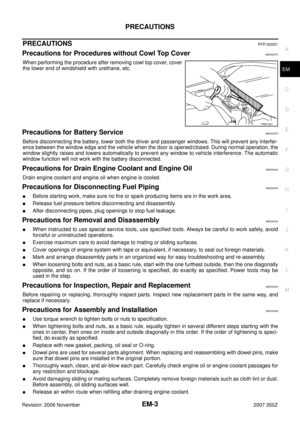 3
3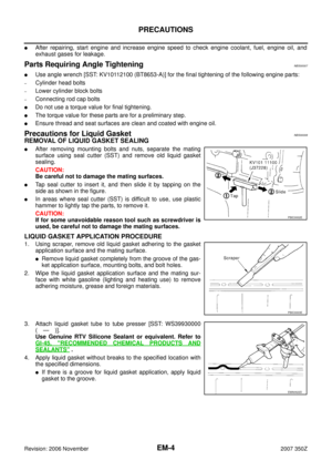 4
4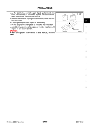 5
5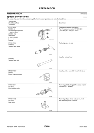 6
6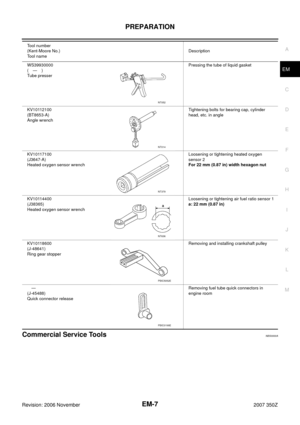 7
7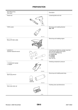 8
8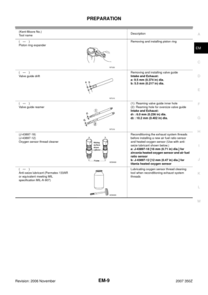 9
9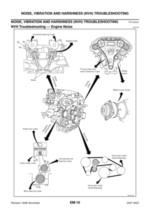 10
10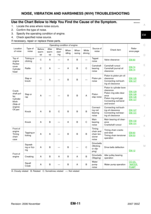 11
11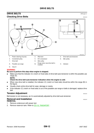 12
12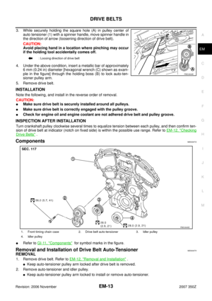 13
13 14
14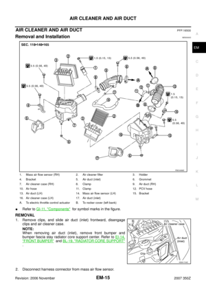 15
15 16
16 17
17 18
18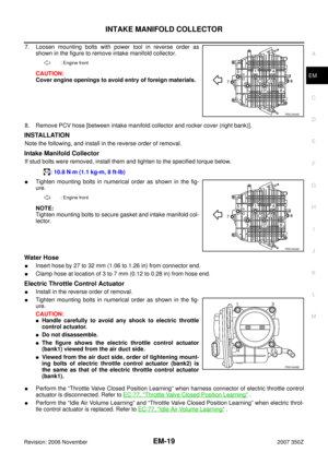 19
19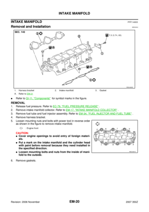 20
20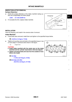 21
21 22
22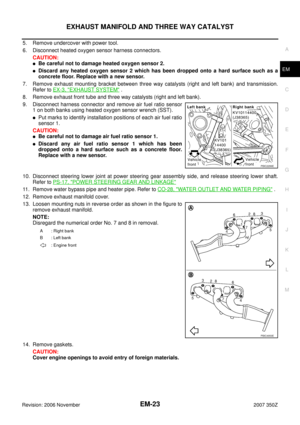 23
23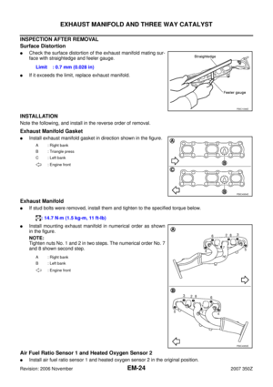 24
24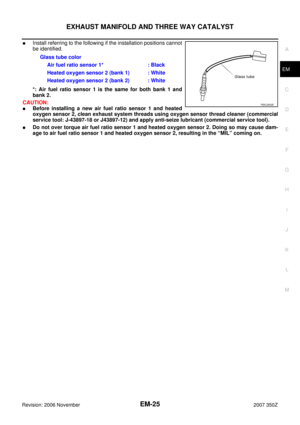 25
25 26
26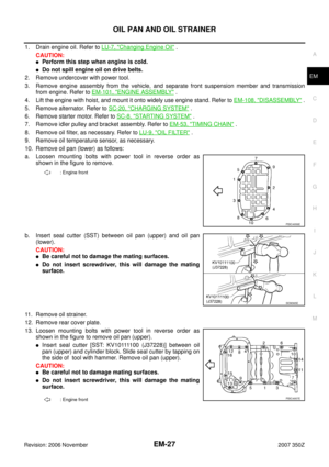 27
27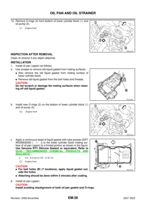 28
28 29
29 30
30 31
31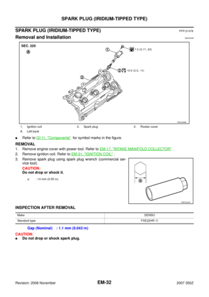 32
32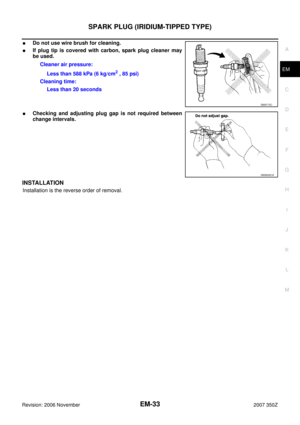 33
33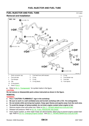 34
34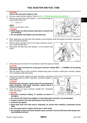 35
35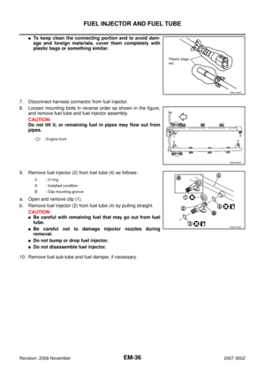 36
36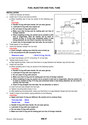 37
37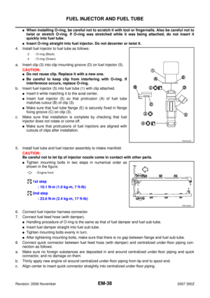 38
38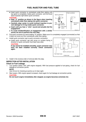 39
39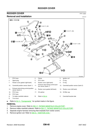 40
40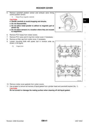 41
41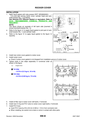 42
42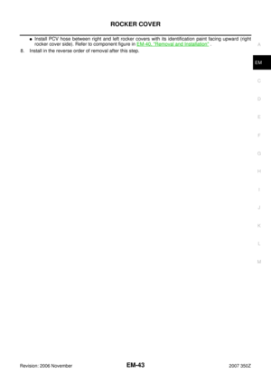 43
43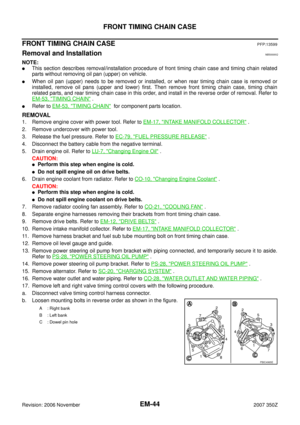 44
44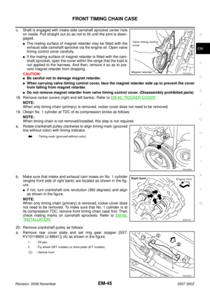 45
45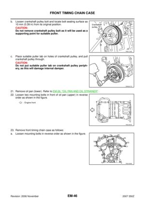 46
46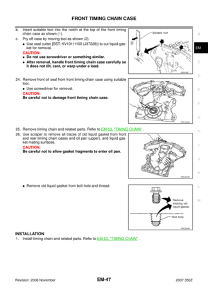 47
47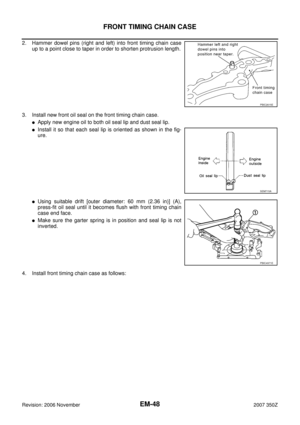 48
48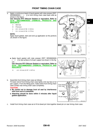 49
49 50
50 51
51 52
52 53
53 54
54 55
55 56
56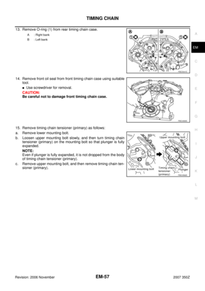 57
57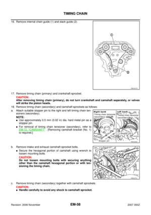 58
58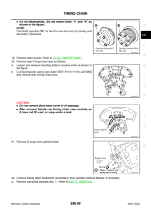 59
59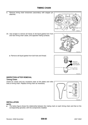 60
60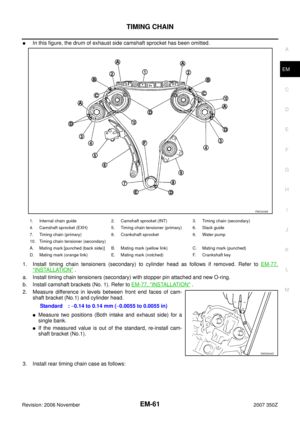 61
61 62
62 63
63 64
64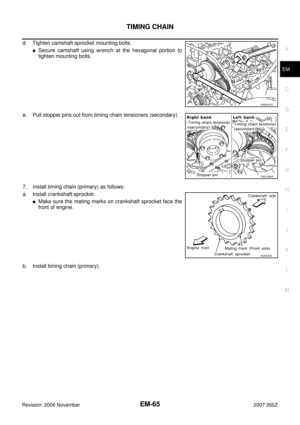 65
65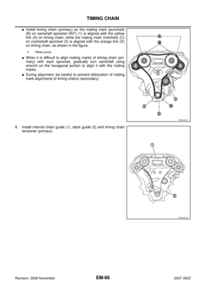 66
66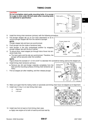 67
67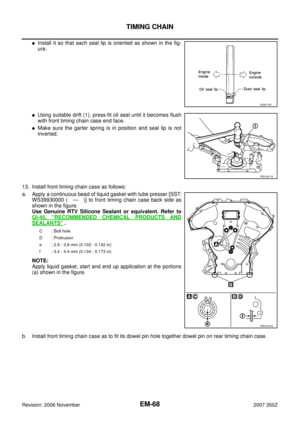 68
68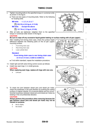 69
69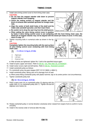 70
70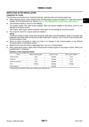 71
71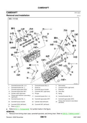 72
72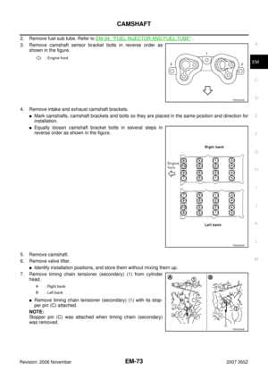 73
73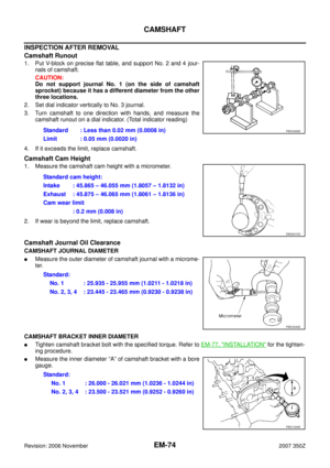 74
74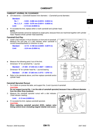 75
75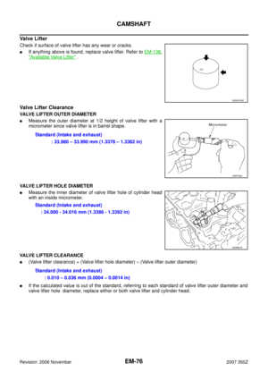 76
76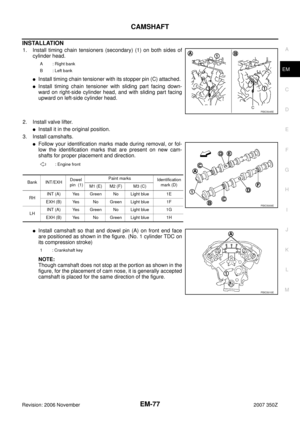 77
77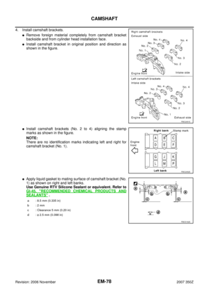 78
78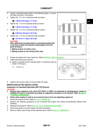 79
79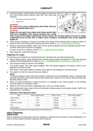 80
80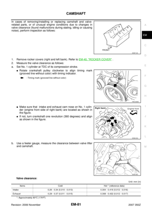 81
81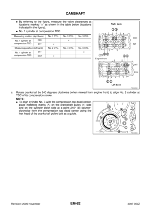 82
82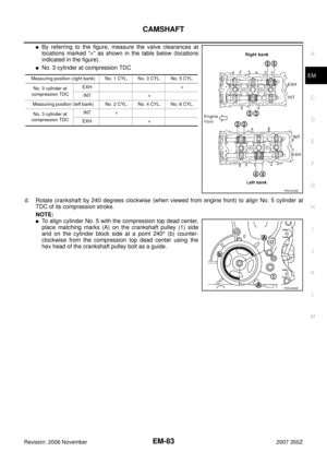 83
83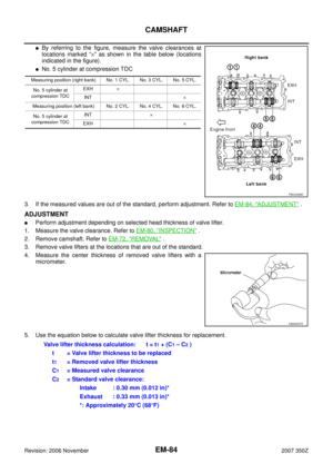 84
84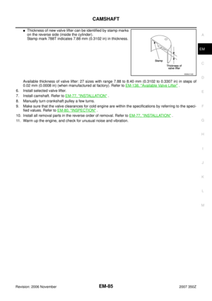 85
85 86
86 87
87 88
88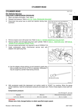 89
89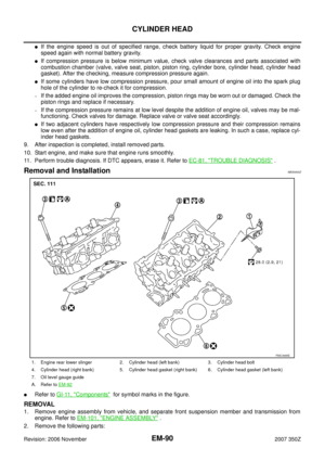 90
90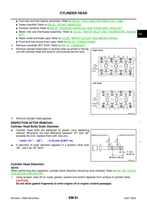 91
91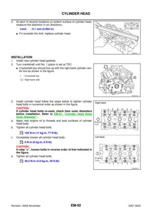 92
92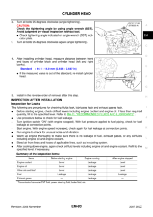 93
93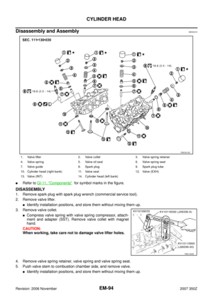 94
94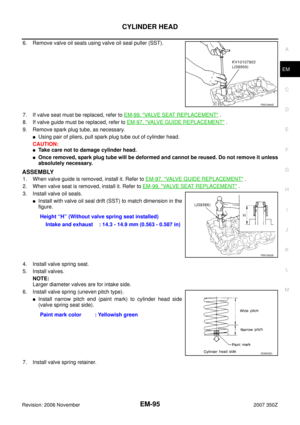 95
95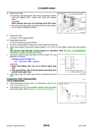 96
96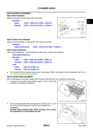 97
97 98
98 99
99 100
100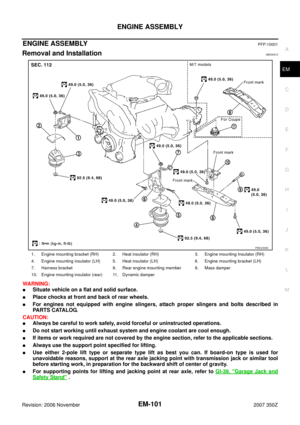 101
101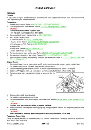 102
102 103
103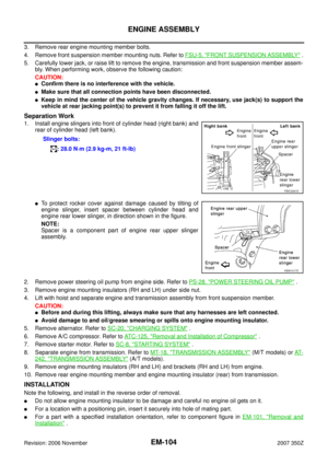 104
104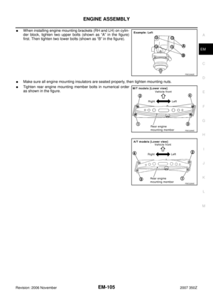 105
105 106
106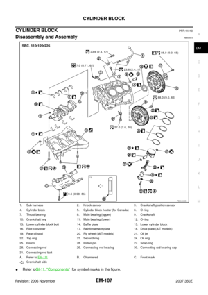 107
107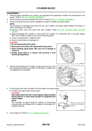 108
108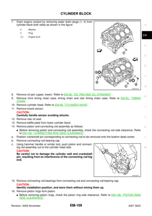 109
109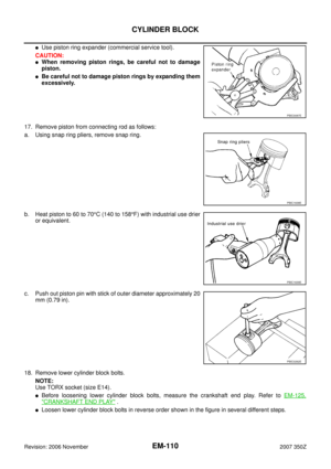 110
110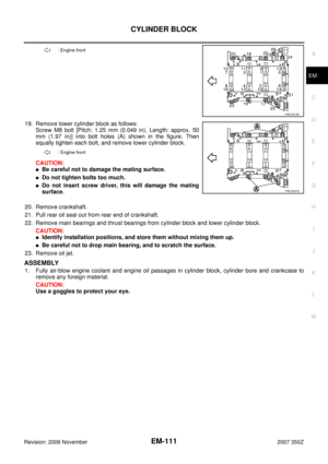 111
111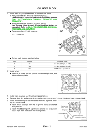 112
112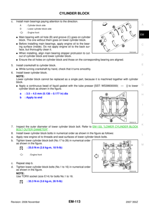 113
113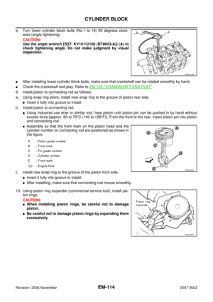 114
114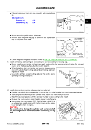 115
115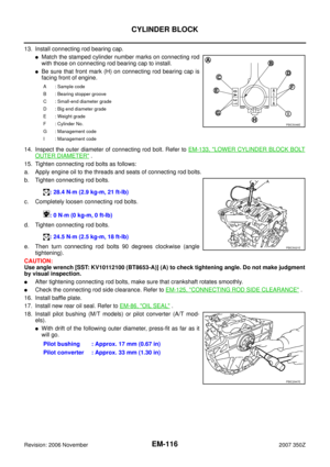 116
116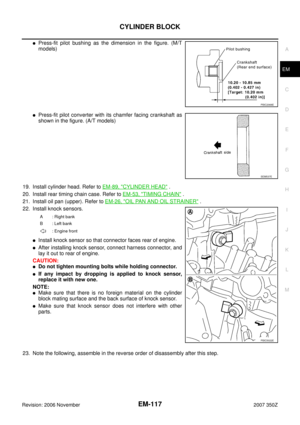 117
117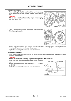 118
118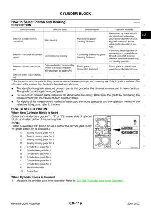 119
119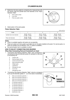 120
120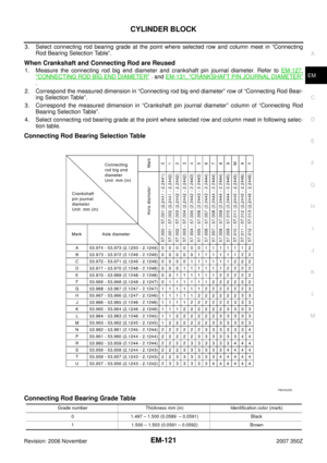 121
121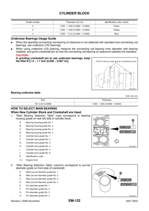 122
122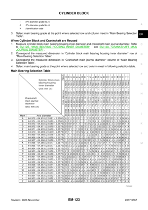 123
123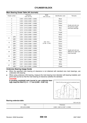 124
124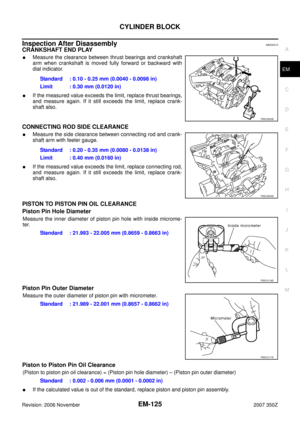 125
125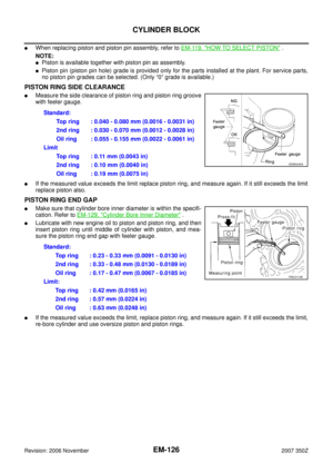 126
126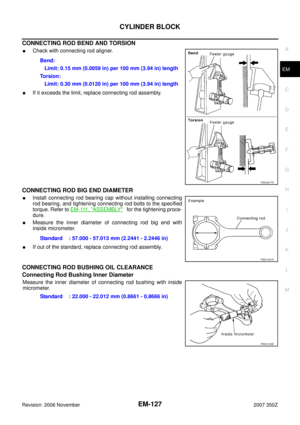 127
127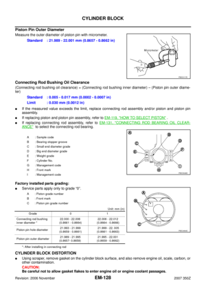 128
128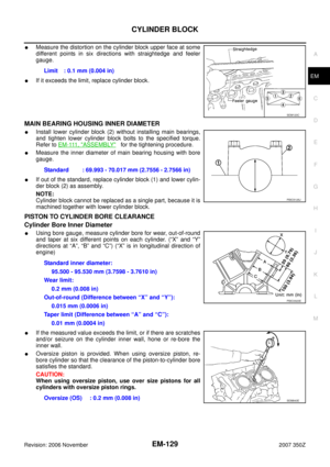 129
129 130
130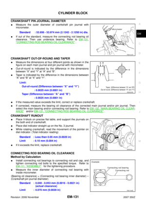 131
131 132
132 133
133 134
134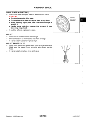 135
135 136
136 137
137 138
138 139
139 140
140 141
141 142
142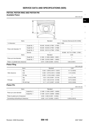 143
143 144
144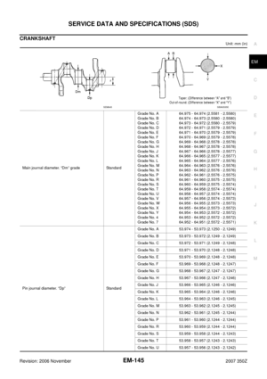 145
145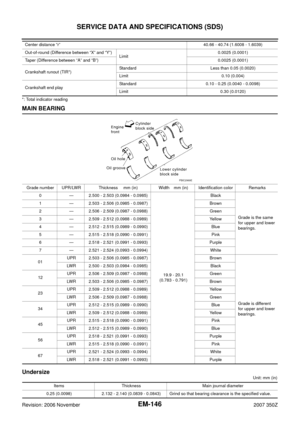 146
146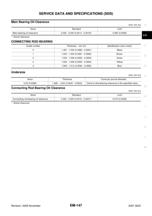 147
147