Page 49 of 148
![NISSAN 350Z 2007 Z33 Engine Mechanical Workshop Manual FRONT TIMING CHAIN CASE
EM-49
C
D
E
F
G
H
I
J
K
L
MA
EM
Revision: 2006 November2007 350Z
a. Apply a continuous bead of liquid gasket with tube presser [SST:
WS39930000 ( — )] to front timing chain c](/manual-img/5/765/w960_765-48.png "NISSAN 350Z 2007 Z33 Engine Mechanical Workshop Manual FRONT TIMING CHAIN CASE
EM-49
C
D
E
F
G
H
I
J
K
L
MA
EM
Revision: 2006 November2007 350Z
a. Apply a continuous bead of liquid gasket with tube presser [SST:
WS39930000 ( — )] to front timing chain c")
FRONT TIMING CHAIN CASE
EM-49
C
D
E
F
G
H
I
J
K
L
MA
EM
Revision: 2006 November2007 350Z
a. Apply a continuous bead of liquid gasket with tube presser [SST:
WS39930000 ( — )] to front timing chain case back side as
shown in the figure.
Use Genuine RTV Silicone Sealant or equivalent. Refer to
GI-45, "
RECOMMENDED CHEMICAL PRODUCTS AND
SEALANTS" .
NOTE:
Apply liquid gasket, start and end up application at the portions
(A) shown in the figure.
�Apply liquid gasket with tube presser [SST: WS39930000
( — )] to top surface of oil pan (upper) as shown in the fig-
ure.
Use Genuine RTV Silicone Sealant or equivalent. Refer to
GI-45, "
RECOMMENDED CHEMICAL PRODUCTS AND
SEALANTS" .
b. Assemble front timing chain case as follows:
Fit lower end of front timing chain case tightly onto top face of oil
pan (upper). From the fitting point, make entire front timing chain
case contact rear timing chain case completely.
CAUTION:
�Be careful not to damage front oil seal by interference
with front end of crankshaft.
�Attaching should be done within 5 minutes after liquid
gasket application.
c. Install front timing chain case as to fit its dowel pin hole together dowel pin on rear timing chain case.
C : Bolt hole
D : Protrusion
e : 2.6 - 3.6 mm (0.102 - 0.142 in)
f : 3.4 - 4.4 mm (0.134 - 0.173 in)
PBIC4972E
A : 4.0 - 5.0 mm (0.157 - 0.197 in)
PBIC5004E
PBIC1100E
Page 50 of 148

EM-50
FRONT TIMING CHAIN CASE
Revision: 2006 November2007 350Z
d. Tighten mounting bolts to the specified torque in numerical order
as shown in the figure.
�There are two types of mounting bolts. Refer to the following
for locating bolts.
e. After all bolts tightened, retighten them to the specified torque in numerical order as shown in the figure.
5. Install two mounting bolts in front of oil pan (upper) in numerical
order as shown in the figure.
6. Install oil pan (lower). Refer to EM-26, "
OIL PAN AND OIL STRAINER" .
7. Install right and left valve timing control covers as follows.
a. Install new seal rings (1) in shaft grooves.
CAUTION:
When replacing seal ring, replace all rings with new one.
b. To check the joint between dowel pins and dowel pin holes,
check the looseness in the axle direction by pushing the mating
surface of magnet retarder (A) at several places and the circum-
ferential looseness (between dowel pins and dowel pin holes) by
twisting in the circumferential direction.
CAUTION:
Always perform this procedure when removing because the
gap between dowel pins and dowel pin holes may not be
caused on purpose.M10 bolts : 1, 2, 3, 4, 5, 6, 7
: 55.0 N·m (5.6 kg-m, 41 ft-lb)
M6 bolts : Except the above
: 12.7 N·m (1.3 kg-m, 9 ft-lb)
PBIC4968E
: 17.2 N·m (1.8 kg-m, 13 ft-lb)
: Engine front
PBIC4967E
A : Left bank
PBIC4973E
B : Moves slightly
C : Not shaken
PBIC4974E
Page 51 of 148

FRONT TIMING CHAIN CASE
EM-51
C
D
E
F
G
H
I
J
K
L
MA
EM
Revision: 2006 November2007 350Z
c. Install valve timing control cover with new gasket to front timing
chain case.
CAUTION:
�Do not face the magnet retarder side down to prevent
magnet retarder from dropping.
�Check the mating surface of magnet retarder and the
drum of exhaust side camshaft sprocket for foreign mate-
rials.
�Align the center of both shaft holes of the shaft and the
intake side camshaft sprocket, and then insert them.
�Be careful not to drop the seal ring from the shaft groove.
�When setting the valve timing control cover in position by hand, if valve timing control cover is
not contacting with the front timing chain case, the dowel pin of magnet retarder may not be
aligned with the dowel pin holes of cover. In this case, return to step “b”.
d. Tighten mounting bolts in numerical order as shown in the fig-
ure.
CAUTION:
Completely tighten the mounting bolts with the seat surface
of valve timing control cover contacting with front timing
chain case.
�After all bolt are tightened, tighten No.1 bolt to the specified torque again.
8. Install crankshaft pulley as follows:
a. Fix crankshaft using ring gear stopper [SST: KV10118600 (J-48641)].
b. Install crankshaft pulley, taking care not to damage front oil seal.
�When press-fitting crankshaft pulley with plastic hammer, tap on its center portion (not circumference).
c. Tighten crankshaft pulley bolt.
d. Place a paint mark (A) on crankshaft pulley (2) aligning with the
angle mark (C) on crankshaft pulley bolt (1). Tighten the bolt 90
degrees (one marks) (b).
9. Rotate crankshaft pulley in normal direction (clockwise when viewed from front) to confirm it turns
smoothly.
10. Install in the reverse order of removal after this step.
INSPECTION AFTER INSTALLATION
Inspection for Leaks
The following are procedures for checking fluid leak, lubricates leak and exhaust gases leak.
�Before starting engine, check oil/fluid levels including engine coolant and engine oil. If less than required
quantity, fill to the specified level. Refer to MA-11, "
RECOMMENDED FLUIDS AND LUBRICANTS" . : 11.3 N·m (1.2 kg-m, 8 ft-lb)
A : Right bank
B : Left bank
C : Dowel pin hole
PBIC3561E
PBIC4965E
: 44.1 N·m (4.5 kg-m, 33 ft-lb)
PBIC4975E
Page 52 of 148

EM-52
FRONT TIMING CHAIN CASE
Revision: 2006 November2007 350Z
�Run engine to check for unusual noise and vibration.
NOTE:
If hydraulic pressure inside timing chain tensioner drops after removal/installation, slack in the guide may
generate a pounding noise during and just after engine start. However, this is normal. Noise will stop after
hydraulic pressure rises.
�Warm up engine thoroughly to make sure there is no leakage of exhaust gases, or any oil/fluids including
engine oil and engine coolant.
�Bleed air from lines and hoses of applicable lines, such as in cooling system.
�After cooling down engine, again check oil/fluid levels including engine oil and engine coolant. Refill to the
specified level, if necessary.
Summary of the inspection items:
* Transmission/transaxle/CVT fluid, power steering fluid, brake fluid, etc.Items Before starting engine Engine running After engine stopped
Engine coolant Level Leakage Level
Engine oil Level Leakage Level
Other oils and fluid* Level Leakage Level
Page 53 of 148
TIMING CHAIN
EM-53
C
D
E
F
G
H
I
J
K
L
MA
EM
Revision: 2006 November2007 350Z
TIMING CHAINPFP:13028
Removal and InstallationNBS0000S
PBIC5165E
Page 54 of 148

EM-54
TIMING CHAIN
Revision: 2006 November2007 350Z
�Refer to GI-11, "Components" for symbol marks in the figure.
NOTE:
�This section describes procedures for removing/installing front timing chain case and timing chain related
parts, and rear timing chain case, when oil pan (upper) needs to be removed/installed for engine overhaul,
etc.
�To remove/install front timing chain case, timing chain, and its related parts without removing oil pan
(upper), refer to EM-44, "
FRONT TIMING CHAIN CASE" .
REMOVAL
1. Remove engine assembly from the vehicle, and separate front suspension member and transmission
from engine. Refer to EM-101, "
ENGINE ASSEMBLY" .
2. Lift the engine with hoist and mount it onto widely use engine stand. Refer to EM-108, "
DISASSEMBLY" .
3. Remove intake manifold collector. Refer to EM-17, "
INTAKE MANIFOLD COLLECTOR" .
4. Remove power steering oil pump bracket. Refer to PS-28, "
POWER STEERING OIL PUMP" .
5. Remove alternator. Refer to SC-20, "
CHARGING SYSTEM" .
6. Remove water bypass hose, water hose clamp and idler pulley bracket from front timing chain case.
7. Remove left and right valve timing control covers (including magnet retarder and cover) with the following
procedure.
a. Loosen mounting bolts in reverse order as shown in the figure.
1.Timing chain tensioner (secondary)
(left bank)2. Internal chain guide 3.Timing chain tensioner (secondary)
(right bank)
4. Camshaft sprocket (EXH) 5. Timing chain (secondary) 6. Timing chain (primary)
7. Camshaft sprocket (INT) 8. Slack guide 9. Timing chain tensioner (primary)
10. Crankshaft sprocket 11. Camshaft sprocket (INT) 12. Timing chain (secondary)
13. Camshaft sprocket (EXH) 14. O-ring 15. Rear timing chain case
16. O-ring 17. O-ring 18. O-ring
19. Bracket 20. Bracket 21. Front timing chain case
22.Valve timing control cover gasket
(LH)23. Valve timing control cover (LH) 24. O-ring
25. Crankshaft pulley bolt 26. Crankshaft pulley 27. Front oil seal
28. Idler pulley 29. O-ring 30. Oil level gauge guide
31. Drive belt auto-tensioner 32. Idler pulley 33. Idler pulley bracket
34. Alternator bracket 35. Water outlet (front) 36.Valve timing control cover gasket
(RH)
37. Valve timing control cover (RH) 38. Power steering oil pump bracket
A. Refer to EM-60
A : Right bank
B : Left bank
C : Dowel pin hole
PBIC4965E
Page 55 of 148

TIMING CHAIN
EM-55
C
D
E
F
G
H
I
J
K
L
MA
EM
Revision: 2006 November2007 350Z
b. Shaft is engaged with intake side camshaft sprocket center hole
on inside. Pull straight out so as not to tilt until the joint is disen-
gaged.
�The mating surface of magnet retarder may be fitted with the
exhaust side camshaft sprocket via the engine oil. Open valve
timing control cover carefully.
�If the mating surface of magnet retarder is fitted with the cam-
shaft sprocket, open the cover within the range that the load is
not applied to the harness. And then, remove it so as to pre-
vent magnet retarder from dropping.
CAUTION:
�Be careful not to damage magnet retarder.
�When carrying valve timing control cover, face the magnet retarder side up to prevent the cover
from falling from magnet retarder.
�Do not remove magnet retarder from valve timing control cover. (Disassembly prohibited parts)
8. Remove rocker covers (right and left banks). Refer to EM-40, "
ROCKER COVER" .
9. Obtain No. 1 cylinder at TDC of its compression stroke as follows:
a. Rotate crankshaft pulley clockwise to align timing mark (grooved
line without color) with timing indicator.
b. Make sure that intake and exhaust cam noses on No. 1 cylinder
(engine front side of right bank) are located as shown in the fig-
ure.
�If not, turn crankshaft one revolution (360 degrees) and align
as shown in the figure.
10. Remove crankshaft pulley as follows:
a. Remove rear cover plate and set ring gear stopper [SST:
KV10118600 (J-48641)] (A) as shown in the figure.
: Timing mark (grooved line without color)
PBIC3561E
PBIC4966E
SEM418G
1 : Oil pan
2 : Fly wheel (M/T models) or drive plate (A/T models)
: Vehicle front
PBIC5051E
Page 56 of 148
 from its original position.
CAUTION:
Do not remove crankshaft pu")
EM-56
TIMING CHAIN
Revision: 2006 November2007 350Z
b. Loosen crankshaft pulley bolt and rotate bolt seating surface at
10 mm (0.39 in) from its original position.
CAUTION:
Do not remove crankshaft pulley bolt as it will be used as a
supporting point for suitable puller.
c. Place suitable puller tab on holes of crankshaft pulley, and pull
crankshaft pulley through.
CAUTION:
Do not put suitable puller tab on crankshaft pulley periph-
ery, as this will damage internal damper.
11. Remove oil pans (upper and lower). Refer to EM-26, "
OIL PAN AND OIL STRAINER" .
12. Remove front timing chain case as follows:
a. Loosen mounting bolts in reverse order as shown in the figure.
b. Insert suitable tool into the notch at the top of the front timing
chain case as shown (1).
c. Pry off case by moving the tool as shown (2).
�U s e s e a l c u t t e r [ S S T: K V 1 0 1111 0 0 ( J 3 7 2 2 8 ) ] t o c u t l i q u i d g a s -
ket for removal.
CAUTION:
�Do not use screwdriver or something similar.
�After removal, handle front timing chain case carefully so
it does not tilt, cant, or warp under a load.
PBIC1103E
EMQ0477D
PBIC4968E
SEM156F
 1
1 2
2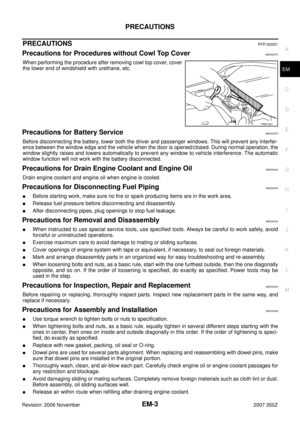 3
3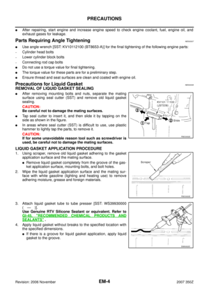 4
4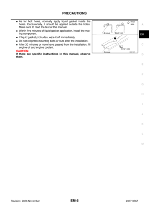 5
5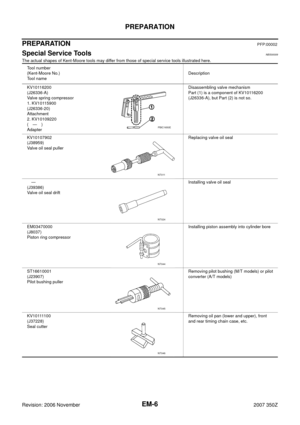 6
6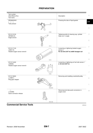 7
7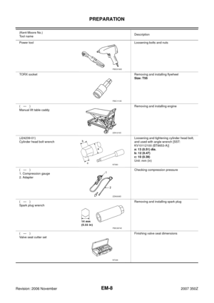 8
8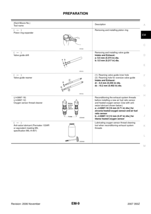 9
9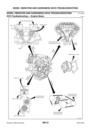 10
10 11
11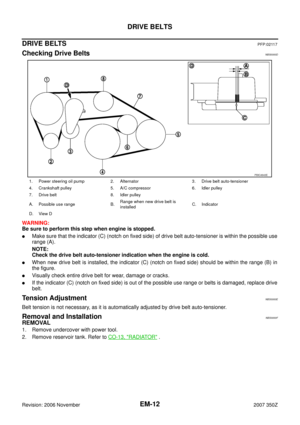 12
12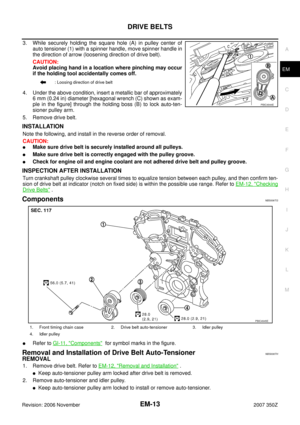 13
13 14
14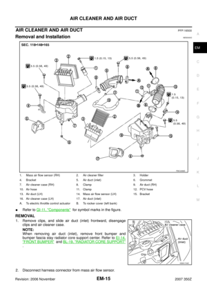 15
15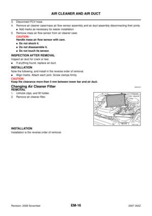 16
16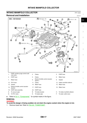 17
17 18
18 19
19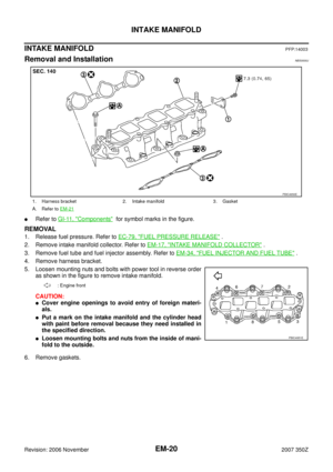 20
20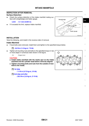 21
21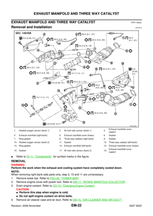 22
22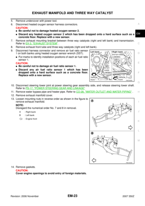 23
23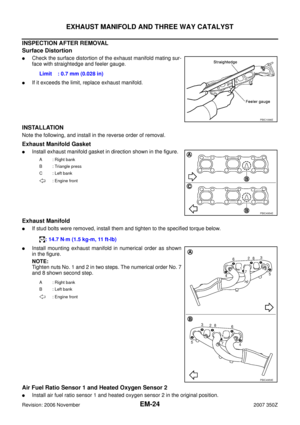 24
24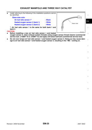 25
25 26
26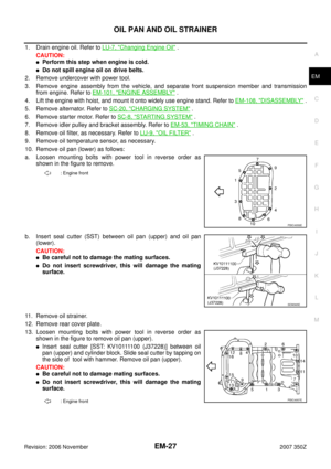 27
27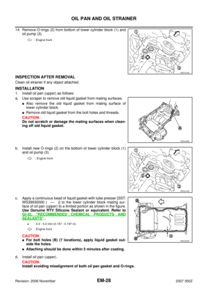 28
28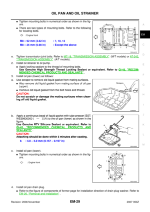 29
29 30
30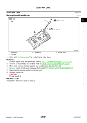 31
31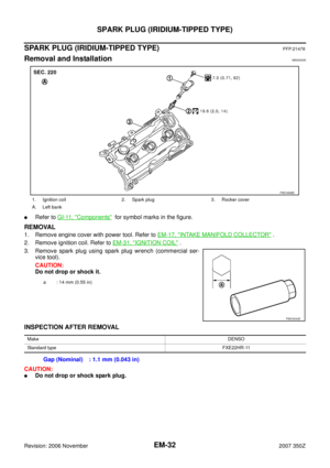 32
32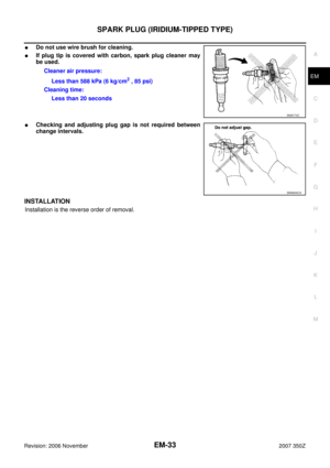 33
33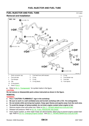 34
34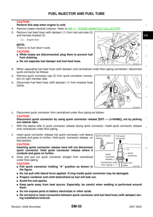 35
35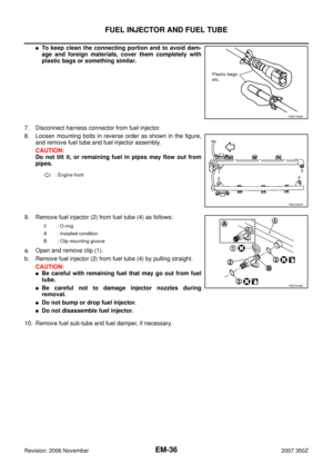 36
36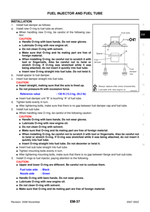 37
37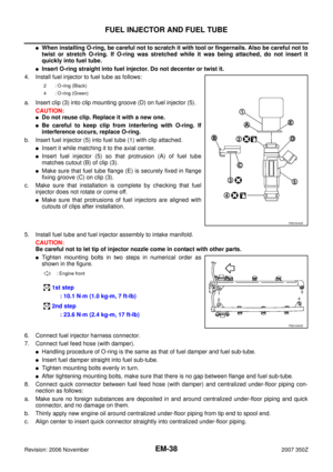 38
38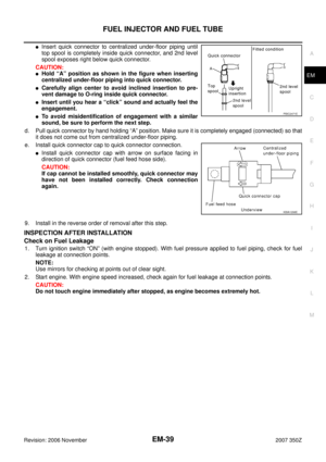 39
39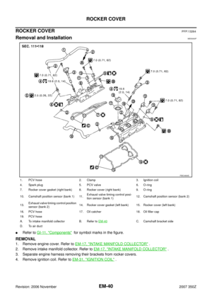 40
40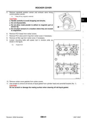 41
41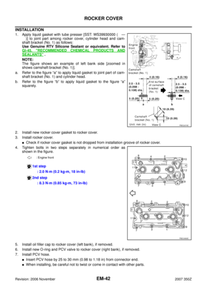 42
42 43
43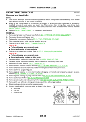 44
44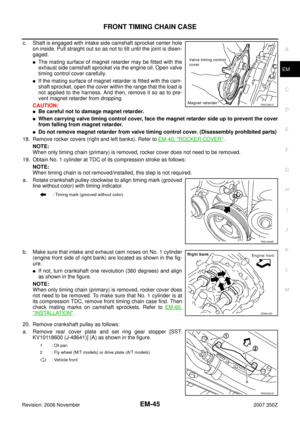 45
45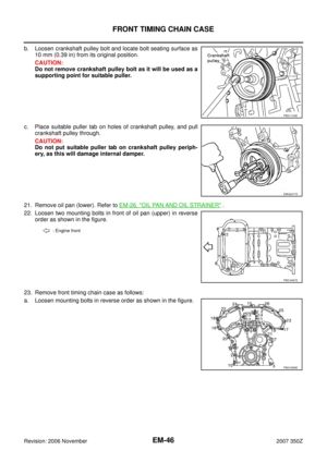 46
46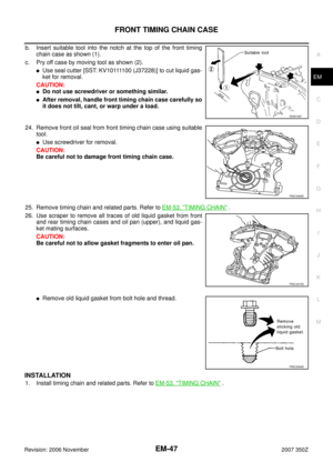 47
47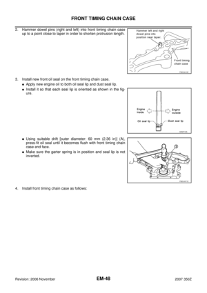 48
48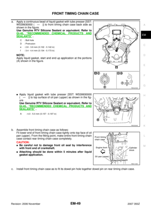 49
49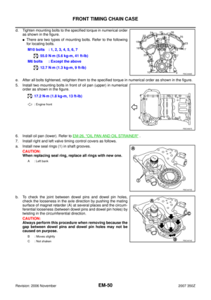 50
50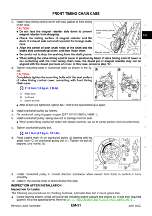 51
51 52
52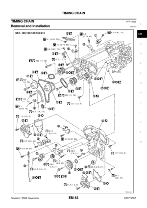 53
53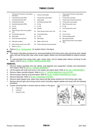 54
54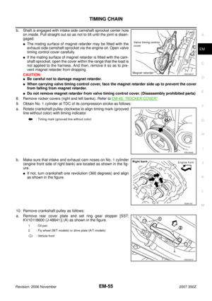 55
55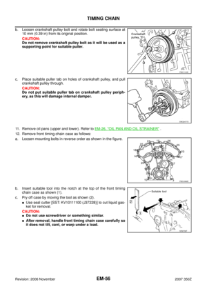 56
56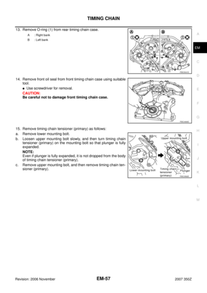 57
57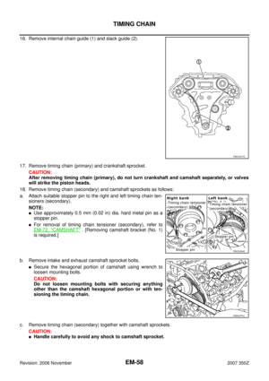 58
58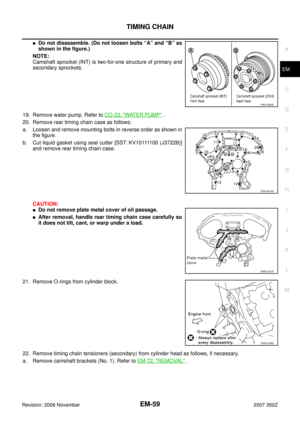 59
59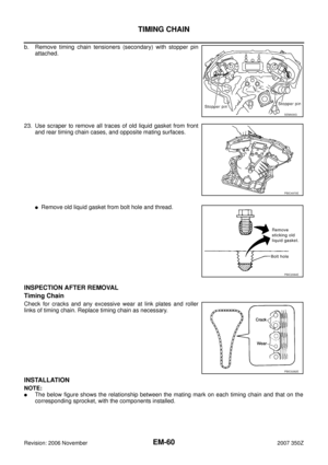 60
60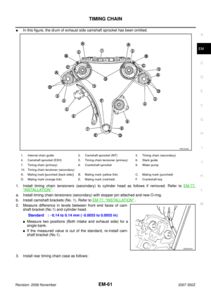 61
61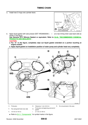 62
62 63
63 64
64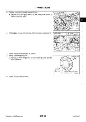 65
65 66
66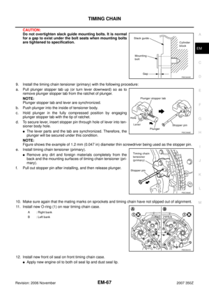 67
67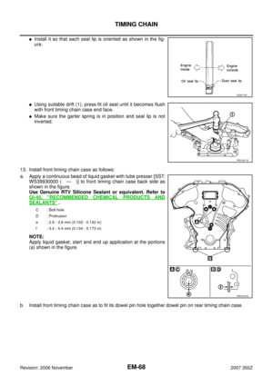 68
68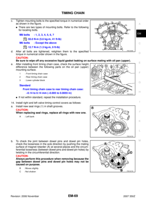 69
69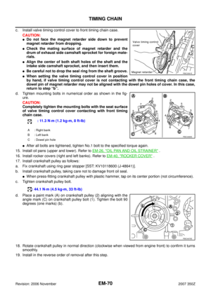 70
70 71
71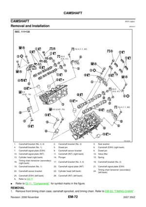 72
72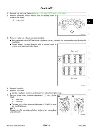 73
73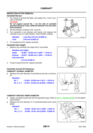 74
74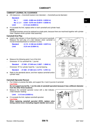 75
75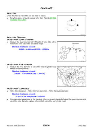 76
76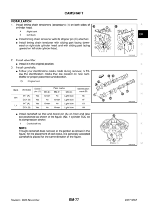 77
77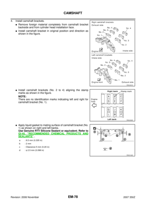 78
78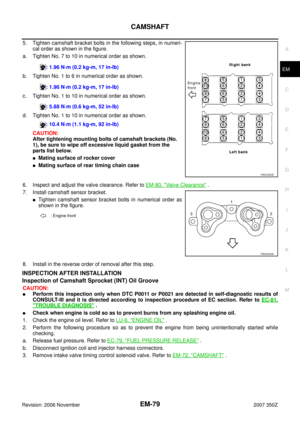 79
79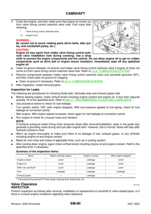 80
80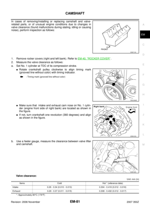 81
81 82
82 83
83 84
84 85
85 86
86 87
87 88
88 89
89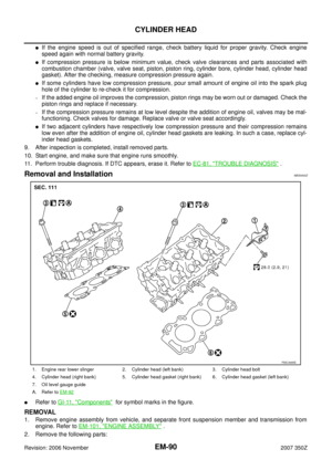 90
90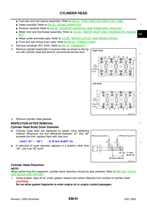 91
91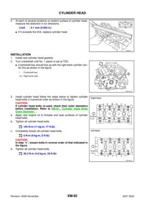 92
92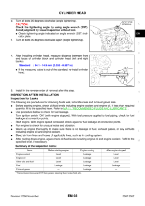 93
93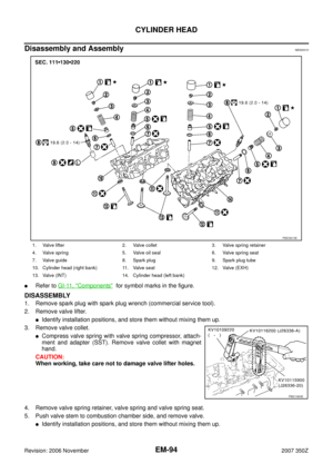 94
94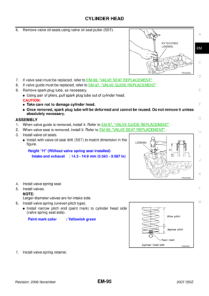 95
95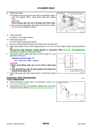 96
96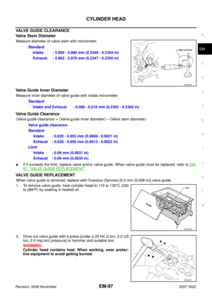 97
97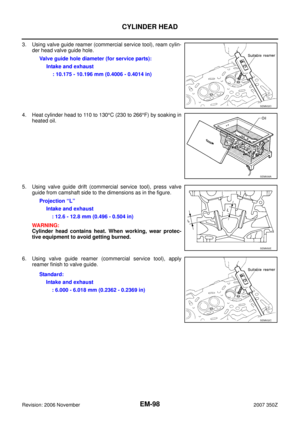 98
98 99
99 100
100 101
101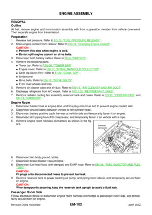 102
102 103
103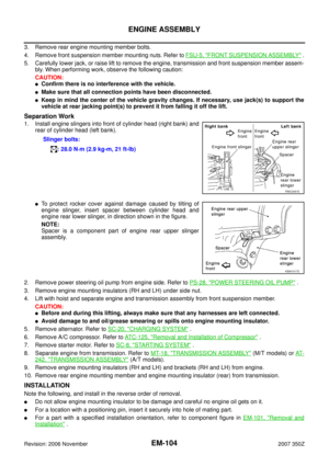 104
104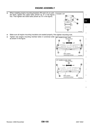 105
105 106
106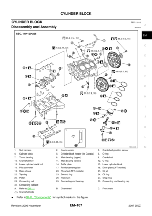 107
107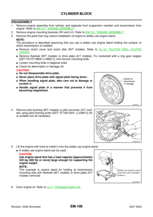 108
108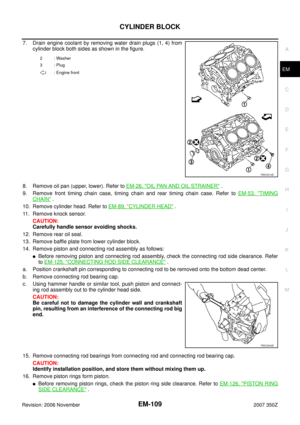 109
109 110
110 111
111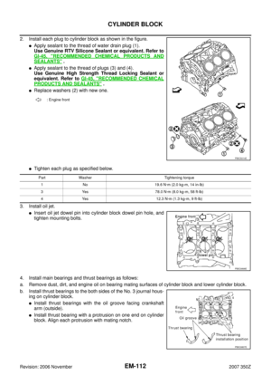 112
112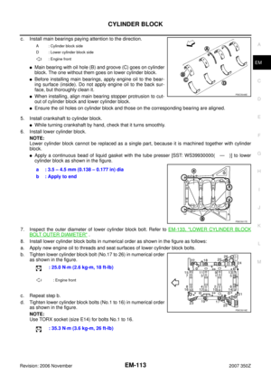 113
113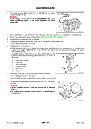 114
114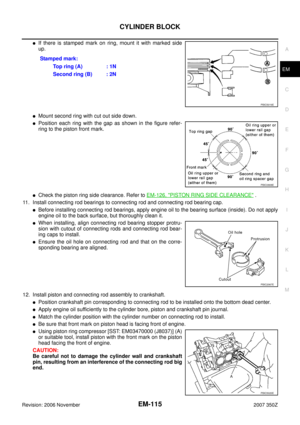 115
115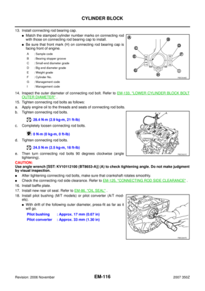 116
116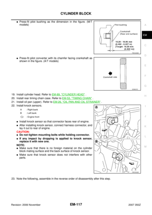 117
117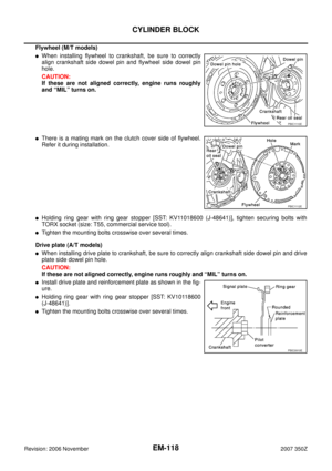 118
118 119
119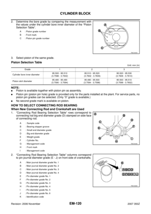 120
120 121
121 122
122 123
123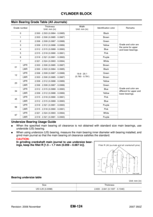 124
124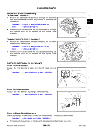 125
125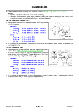 126
126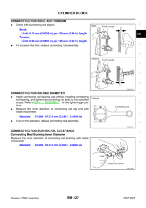 127
127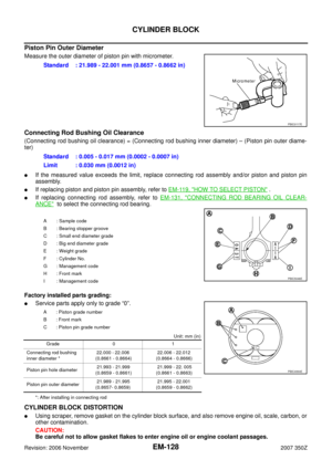 128
128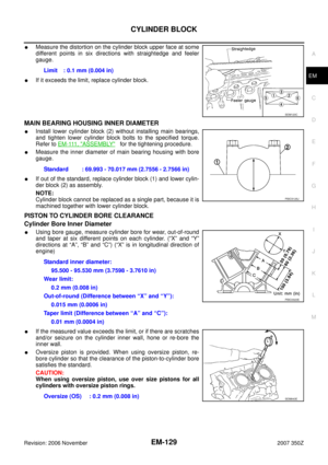 129
129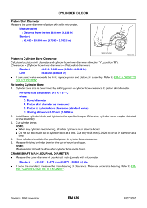 130
130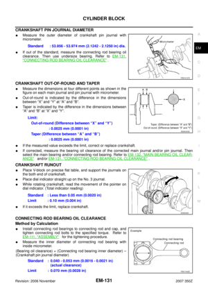 131
131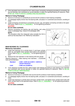 132
132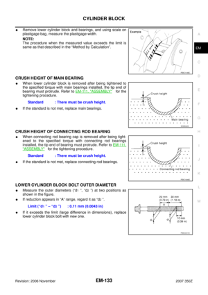 133
133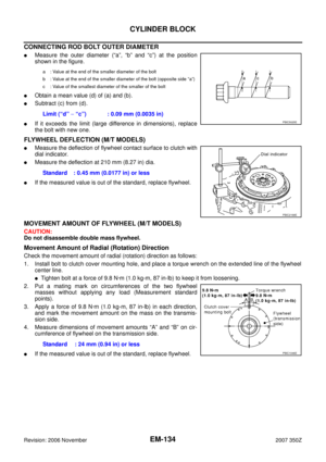 134
134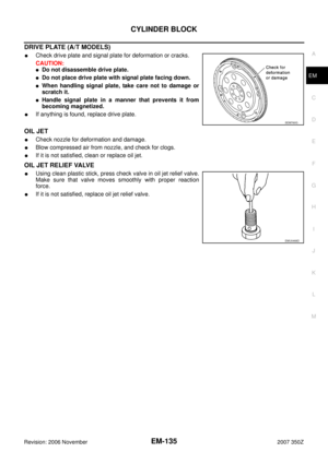 135
135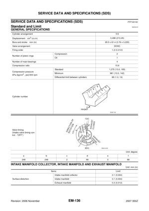 136
136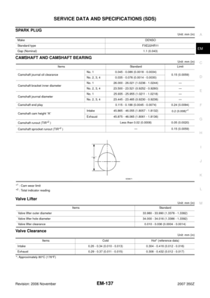 137
137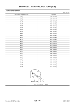 138
138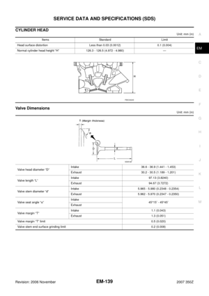 139
139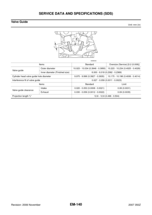 140
140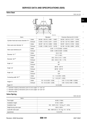 141
141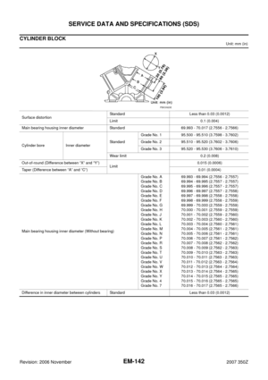 142
142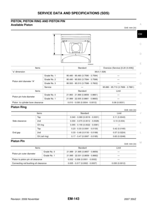 143
143 144
144 145
145 146
146 147
147