Page 89 of 148

CYLINDER HEAD
EM-89
C
D
E
F
G
H
I
J
K
L
MA
EM
Revision: 2006 November2007 350Z
CYLINDER HEADPFP:11041
On-Vehicle ServiceNBS0000Y
CHECKING COMPRESSION PRESSURE
1. Warm up engine thoroughly. Then, stop it.
2. Release fuel pressure. Refer to EC-79, "
FUEL PRESSURE RELEASE" .
3. Disconnect fuel pump fuse to avoid fuel injection during mea-
surement.
4. Remove engine cover with power tool. Refer to EM-17, "
INTAKE MANIFOLD COLLECTOR" .
5. Remove ignition coil and spark plug from each cylinder. Refer to EM-31, "
IGNITION COIL" and EM-32,
"SPARK PLUG (IRIDIUM-TIPPED TYPE)" .
6. Connect engine tachometer (not required in use of CONSULT-III).
7. Install compression tester (Commercial service tool) with
adapter onto spark plug hole.
�Use the adapter whose picking up end inserted to spark plug
hole is smaller than 20 mm (0.79 in) in diameter. Otherwise, it
may be caught by cylinder head during removal.
8. With accelerator pedal fully depressed, turn ignition switch to “START” for cranking. When the gauge
pointer stabilizes, read the compression pressure and engine rpm. Perform these steps to check each cyl-
inder.
Compression pressure:
Unit: kPa (kg/cm2 , psi) /rpm
CAUTION:
Always use a fully changed battery to obtain specified engine speed.
PBIC2058E
PBIC0900E
SBIA0533E
Standard Minimum Differential limit between cylinders
1,275 (13.0, 185)/300 981 (10.0, 142)/300 98 (1.0, 14)/300
Page 90 of 148

EM-90
CYLINDER HEAD
Revision: 2006 November2007 350Z
�If the engine speed is out of specified range, check battery liquid for proper gravity. Check engine
speed again with normal battery gravity.
�If compression pressure is below minimum value, check valve clearances and parts associated with
combustion chamber (valve, valve seat, piston, piston ring, cylinder bore, cylinder head, cylinder head
gasket). After the checking, measure compression pressure again.
�If some cylinders have low compression pressure, pour small amount of engine oil into the spark plug
hole of the cylinder to re-check it for compression.
–If the added engine oil improves the compression, piston rings may be worn out or damaged. Check the
piston rings and replace if necessary.
–If the compression pressure remains at low level despite the addition of engine oil, valves may be mal-
functioning. Check valves for damage. Replace valve or valve seat accordingly.
�If two adjacent cylinders have respectively low compression pressure and their compression remains
low even after the addition of engine oil, cylinder head gaskets are leaking. In such a case, replace cyl-
inder head gaskets.
9. After inspection is completed, install removed parts.
10. Start engine, and make sure that engine runs smoothly.
11. Perform trouble diagnosis. If DTC appears, erase it. Refer to EC-81, "
TROUBLE DIAGNOSIS" .
Removal and InstallationNBS0000Z
�Refer to GI-11, "Components" for symbol marks in the figure.
REMOVAL
1. Remove engine assembly from vehicle, and separate front suspension member and transmission from
engine. Refer to EM-101, "
ENGINE ASSEMBLY" .
2. Remove the following parts:
1. Engine rear lower slinger 2. Cylinder head (left bank) 3. Cylinder head bolt
4. Cylinder head (right bank) 5. Cylinder head gasket (right bank) 6. Cylinder head gasket (left bank)
7. Oil level gauge guide
A. Refer to EM-92
PBIC4985E
Page 91 of 148

CYLINDER HEAD
EM-91
C
D
E
F
G
H
I
J
K
L
MA
EM
Revision: 2006 November2007 350Z
�Fuel tube and fuel injector assembly: Refer to EM-34, "FUEL INJECTOR AND FUEL TUBE" .
�Intake manifold: Refer to EM-20, "INTAKE MANIFOLD" .
�Exhaust manifold: Refer to EM-22, "EXHAUST MANIFOLD AND THREE WAY CATALYST" .
�Water inlet and thermostat assembly: Refer to CO-26, "WATER INLET AND THERMOSTAT ASSEM-
BLY" .
�Water outlet and water pipe: Refer to CO-28, "WATER OUTLET AND WATER PIPING" .
�Front and rear timing chain case: Refer to EM-53, "TIMING CHAIN" .
3. Remove camshaft (INT, EXH). Refer to EM-72, "
CAMSHAFT" .
4. Remove cylinder head bolts in reverse order as shown in the fig-
ure with cylinder head bolt wrench (commercial service tool).
5. Remove cylinder head gaskets.
INSPECTION AFTER REMOVAL
Cylinder Head Bolts Outer Diameter
�Cylinder head bolts are tightened by plastic zone tightening
method. Whenever the size difference between “d1” and “d2”
exceeds the limit, replace them with new one.
�If reduction of outer diameter appears in a position other than
“d2”, use it as “d2” point.
Cylinder Head Distortion
NOTE:
When performing this inspection, cylinder block distortion should be also checked. Refer to EM-128, "
CYLIN-
DER BLOCK DISTORTION" .
1. Using scraper, wipe off oil, scale, gasket, sealant and carbon deposits from surface of cylinder head.
CAUTION:
Do not allow gasket fragments to enter engine oil or engine coolant passages.
PBIC2057E
Limit (“d1” – “d2”) : 0.18 mm (0.0071 in)
PBIC2480E
Page 92 of 148

EM-92
CYLINDER HEAD
Revision: 2006 November2007 350Z
2. At each of several locations on bottom surface of cylinder head,
measure the distortion in six directions.
�If it exceeds the limit, replace cylinder head.
INSTALLATION
1. Install new cylinder head gaskets.
2. Turn crankshaft until No. 1 piston is set at TDC.
�Crankshaft key should line up with the right bank cylinder cen-
ter line as shown in the figure.
3. Install cylinder head follow the steps below to tighten cylinder
head bolts in numerical order as shown in the figure.
CAUTION:
If cylinder head bolts re-used, check their outer diameters
before installation. Refer to EM-91, "
Cylinder Head Bolts
Outer Diameter" .
a. Apply new engine oil to threads and seat surfaces of cylinder
head bolts.
b. Tighten all cylinder head bolts.
c. Completely loosen all cylinder head bolts.
CAUTION:
In step “c”, loosen bolts in reverse order of that indicated in
the figure.
d. Tighten all cylinder head bolts.Limit : 0.1 mm (0.004 in)
SEM861E
1 : Crankshaft key
: Right bank side
PBIC5012E
: 105 N·m (11 kg-m, 77 ft-lb)
: 0 N·m (0 kg-m, 0 ft-lb)
: 39.2 N·m (4.0 kg-m, 29 ft-lb)
PBIC2057E
Page 93 of 148
.
CAUTION:
Check the tightening angle by using angle wrench (SST")
CYLINDER HEAD
EM-93
C
D
E
F
G
H
I
J
K
L
MA
EM
Revision: 2006 November2007 350Z
e. Turn all bolts 95 degrees clockwise (angle tightening).
CAUTION:
Check the tightening angle by using angle wrench (SST).
Avoid judgment by visual inspection without tool.
�Check tightening angle indicated on angle wrench (SST) indi-
cator plate.
f. Turn all bolts 95 degrees clockwise again (angle tightening).
4. After installing cylinder head, measure distance between front
end faces of cylinder block and cylinder head (left and right
banks).
�If the measured value is out of the standard, re-install cylinder
head.
5. Install in the reverse order of removal after this step.
INSPECTION AFTER INSTALLATION
Inspection for Leaks
The following are procedures for checking fluids leak, lubricates leak and exhaust gases leak.
�Before starting engine, check oil/fluid levels including engine coolant and engine oil. If less than required
quantity, fill to the specified level. Refer to MA-11, "
RECOMMENDED FLUIDS AND LUBRICANTS" .
�Use procedure below to check for fuel leakage.
–Turn ignition switch “ON” (with engine stopped). With fuel pressure applied to fuel piping, check for fuel
leakage at connection points.
–Start engine. With engine speed increased, check again for fuel leakage at connection points.
�Run engine to check for unusual noise and vibration.
�Warm up engine thoroughly to make sure there is no leakage of fuel, exhaust gases, or any oil/fluids
including engine oil and engine coolant.
�Bleed air from lines and hoses of applicable lines, such as in cooling system.
�After cooling down engine, again check oil/fluid levels including engine oil and engine coolant. Refill to the
specified level, if necessary.
Summary of the inspection items:
* Transmission/transaxle/CVT fluid, power steering fluid, brake fluid, etc.
PBIC0888E
Standard : 14.1 - 14.9 mm (0.555 - 0.587 in)
EMQ0662D
Items Before starting engine Engine running After engine stopped
Engine coolant Level Leakage Level
Engine oil Level Leakage Level
Other oils and fluid* Level Leakage Level
Fuel Leakage Leakage Leakage
Exhaust gases — Leakage —
Page 94 of 148

EM-94
CYLINDER HEAD
Revision: 2006 November2007 350Z
Disassembly and AssemblyNBS00010
�Refer to GI-11, "Components" for symbol marks in the figure.
DISASSEMBLY
1. Remove spark plug with spark plug wrench (commercial service tool).
2. Remove valve lifter.
�Identify installation positions, and store them without mixing them up.
3. Remove valve collet.
�Compress valve spring with valve spring compressor, attach-
ment and adapter (SST). Remove valve collet with magnet
hand.
CAUTION:
When working, take care not to damage valve lifter holes.
4. Remove valve spring retainer, valve spring and valve spring seat.
5. Push valve stem to combustion chamber side, and remove valve.
�Identify installation positions, and store them without mixing them up.
1. Valve lifter 2. Valve collet 3. Valve spring retainer
4. Valve spring 5. Valve oil seal 6. Valve spring seat
7. Valve guide 8. Spark plug 9. Spark plug tube
10. Cylinder head (right bank) 11. Valve seat 12. Valve (EXH)
13. Valve (INT) 14. Cylinder head (left bank)
PBIC5013E
PBIC1803E
Page 95 of 148
.
7. If valve seat must be replaced, refer to EM-99, \"
VALVE S")
CYLINDER HEAD
EM-95
C
D
E
F
G
H
I
J
K
L
MA
EM
Revision: 2006 November2007 350Z
6. Remove valve oil seals using valve oil seal puller (SST).
7. If valve seat must be replaced, refer to EM-99, "
VALVE SEAT REPLACEMENT" .
8. If valve guide must be replaced, refer to EM-97, "
VALVE GUIDE REPLACEMENT" .
9. Remove spark plug tube, as necessary.
�Using pair of pliers, pull spark plug tube out of cylinder head.
CAUTION:
�Take care not to damage cylinder head.
�Once removed, spark plug tube will be deformed and cannot be reused. Do not remove it unless
absolutely necessary.
ASSEMBLY
1. When valve guide is removed, install it. Refer to EM-97, "VALVE GUIDE REPLACEMENT" .
2. When valve seat is removed, install it. Refer to EM-99, "
VALVE SEAT REPLACEMENT" .
3. Install valve oil seals.
�Install with valve oil seal drift (SST) to match dimension in the
figure.
4. Install valve spring seat.
5. Install valves.
NOTE:
Larger diameter valves are for intake side.
6. Install valve spring (uneven pitch type).
�Install narrow pitch end (paint mark) to cylinder head side
(valve spring seat side).
7. Install valve spring retainer.
PBIC0884E
Height “H” (Without valve spring seat installed)
Intake and exhaust : 14.3 - 14.9 mm (0.563 - 0.587 in)
PBIC0802E
Paint mark color : Yellowish green
SEM085D
Page 96 of 148
. Install valve collet with magnet
hand")
EM-96
CYLINDER HEAD
Revision: 2006 November2007 350Z
8. Install valve collet.
�Compress valve spring with valve spring compressor, attach-
ment and adapter (SST). Install valve collet with magnet
hand.
CAUTION:
When working, take care not to damage valve lifter holes.
�Tap valve stem edge lightly with plastic hammer after installa-
tion to check its installed condition.
9. Install valve lifter.
�Install it in the original position.
10. Install spark plug tube.
�Press-fit spark plug tube as follows:
a. Remove old liquid gasket adhering to cylinder head mounting hole.
b. Apply liquid gasket to area within approximately 12 mm (0.47 in) from edge of spark plug tube press-fit
side.
Use Genuine High Strength Locking Sealant or equivalent. Refer to GI-45, "
RECOMMENDED
CHEMICAL PRODUCTS AND SEALANTS" .
c. Using drift, press-fit spark plug tube so that its height “H” is as
specified in the figure.
CAUTION:
�When press-fitting, take care not to deform spark plug
tube.
�After press-fitting, wipe off liquid gasket protruding onto
cylinder-head upper face.
11. Install spark plug with spark plug wrench (commercial service
tool).
Inspection After DisassemblyNBS00011
VALVE DIMENSIONS
�Check dimensions of each valve. For dimensions, refer to EM-
139, "Valve Dimensions" .
�If dimensions are out of the standard, replace valve and check
valve seat contact. Refer to EM-99, "
VALVE SEAT CONTACT" .
PBIC1803E
Standard press-fit height “H”:
: 37.7 - 38.7 mm (1.484 - 1.524 in)
PBIC2638E
SEM188A
 1
1 2
2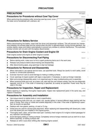 3
3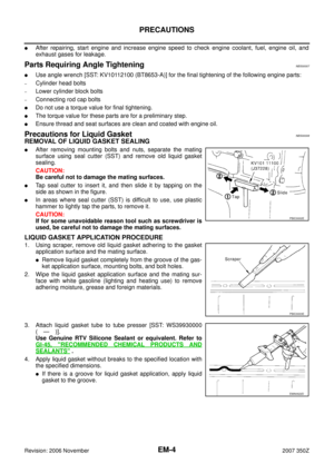 4
4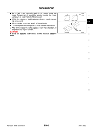 5
5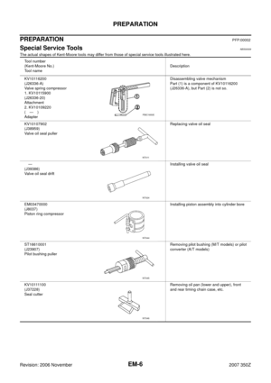 6
6 7
7 8
8 9
9 10
10 11
11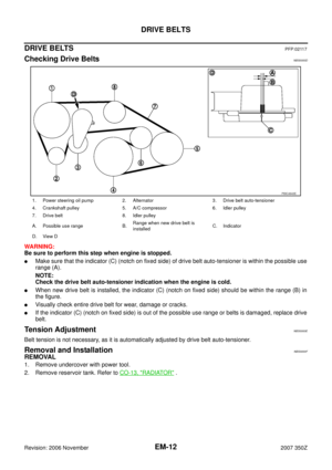 12
12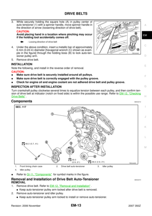 13
13 14
14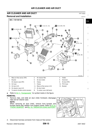 15
15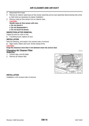 16
16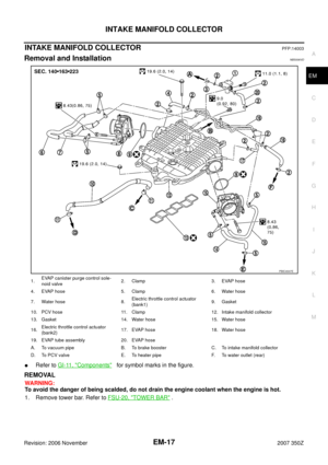 17
17 18
18 19
19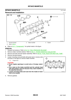 20
20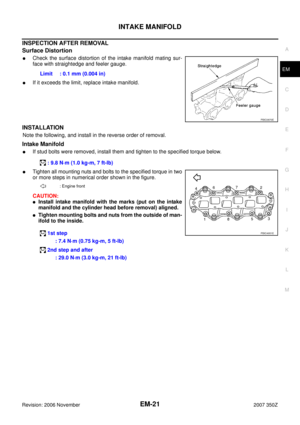 21
21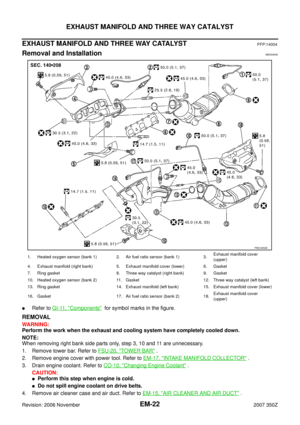 22
22 23
23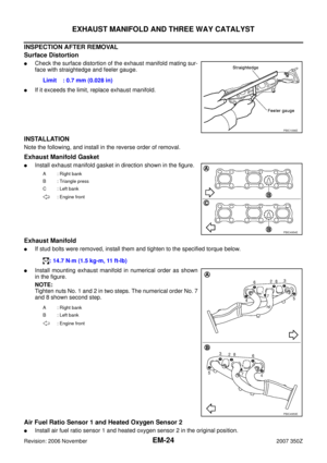 24
24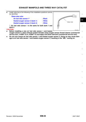 25
25 26
26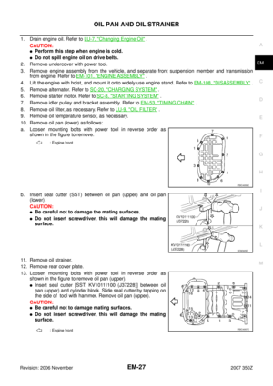 27
27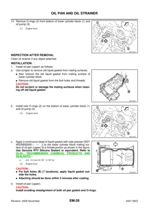 28
28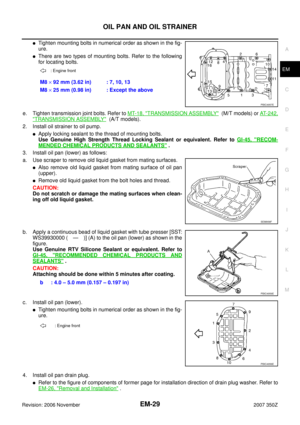 29
29 30
30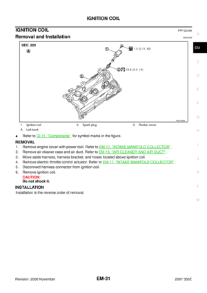 31
31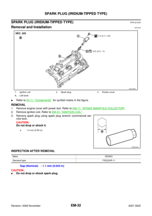 32
32 33
33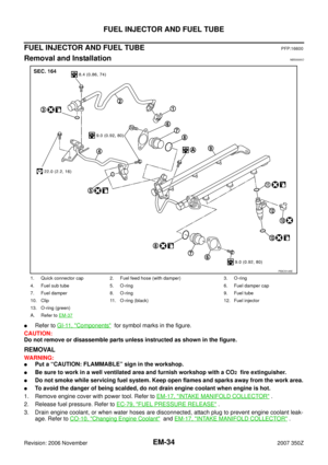 34
34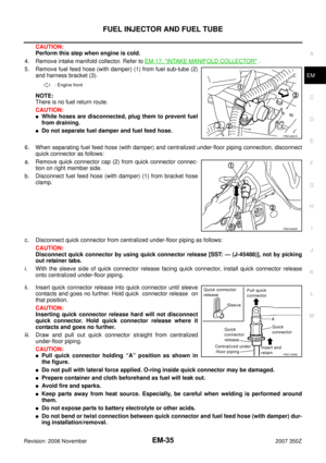 35
35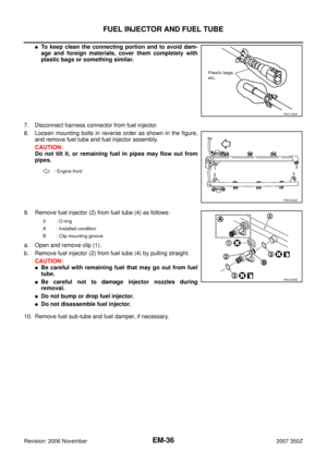 36
36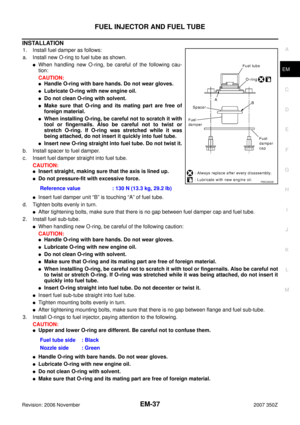 37
37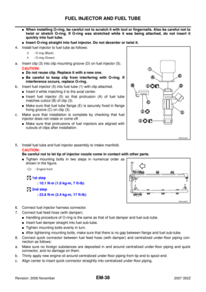 38
38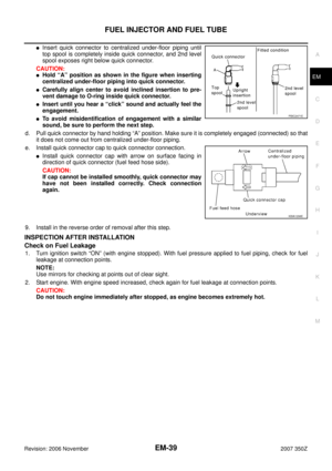 39
39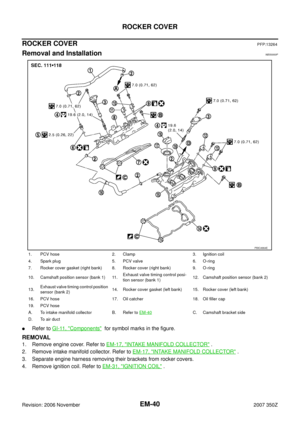 40
40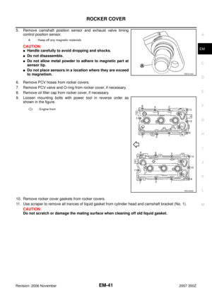 41
41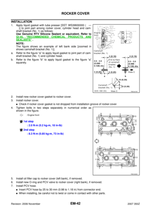 42
42 43
43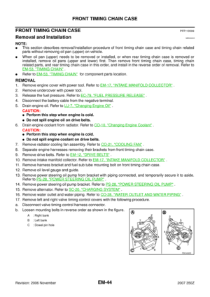 44
44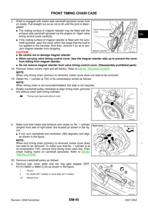 45
45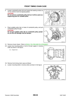 46
46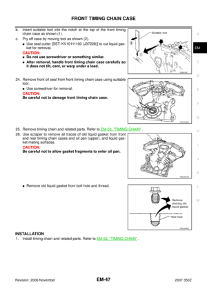 47
47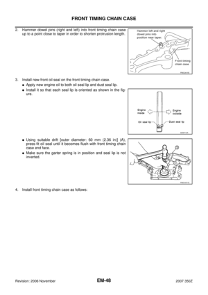 48
48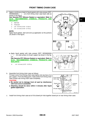 49
49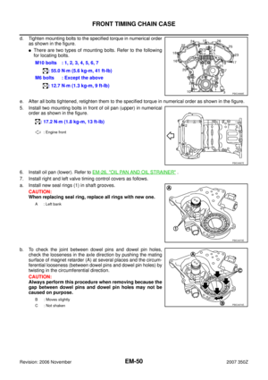 50
50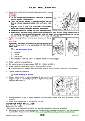 51
51 52
52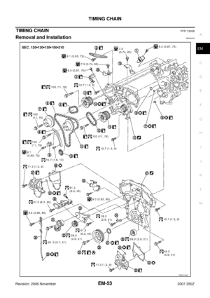 53
53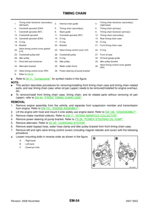 54
54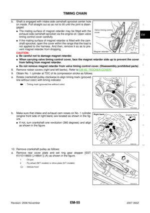 55
55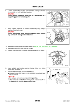 56
56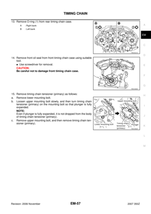 57
57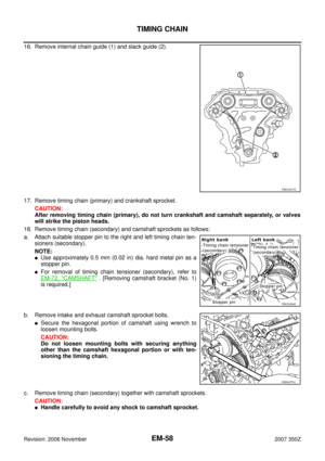 58
58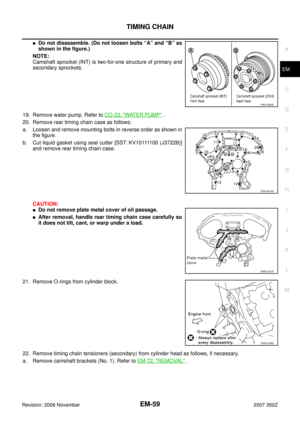 59
59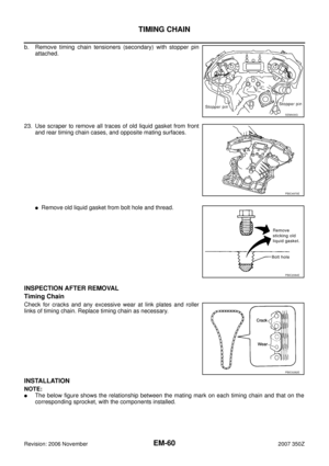 60
60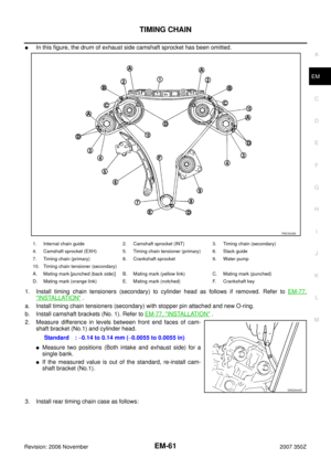 61
61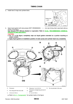 62
62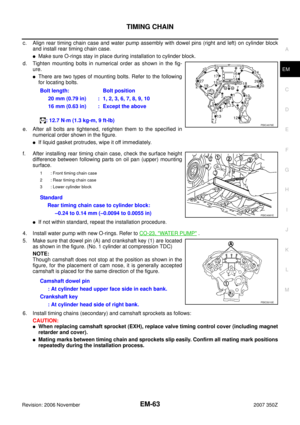 63
63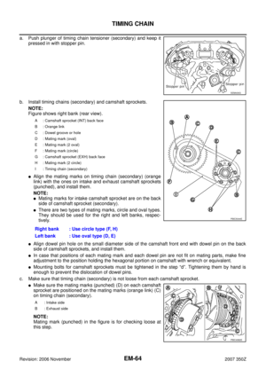 64
64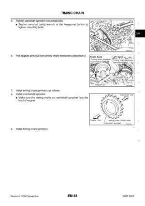 65
65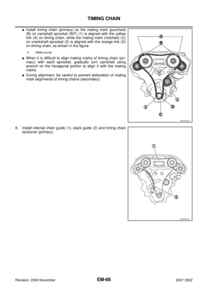 66
66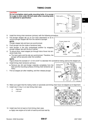 67
67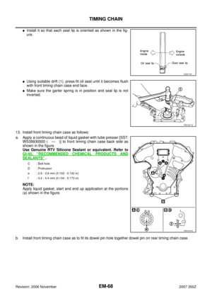 68
68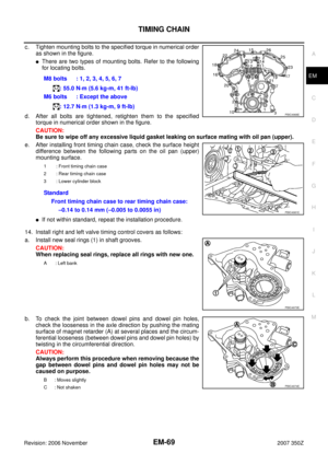 69
69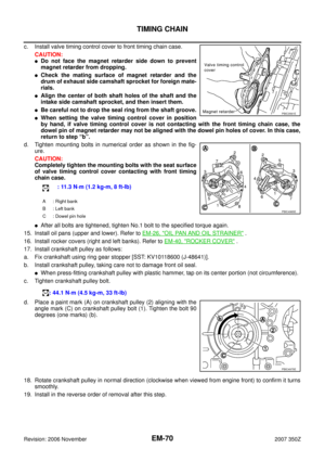 70
70 71
71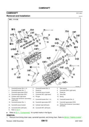 72
72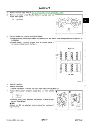 73
73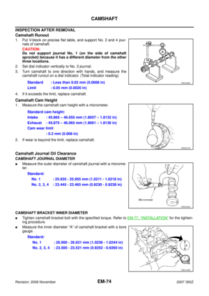 74
74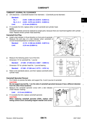 75
75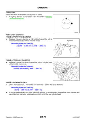 76
76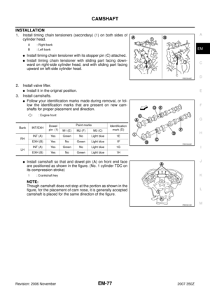 77
77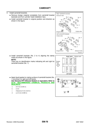 78
78 79
79 80
80 81
81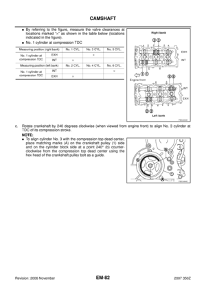 82
82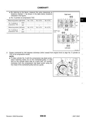 83
83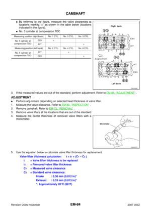 84
84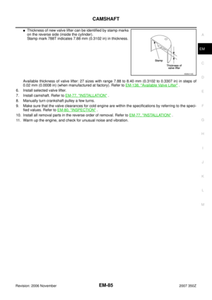 85
85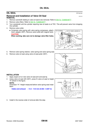 86
86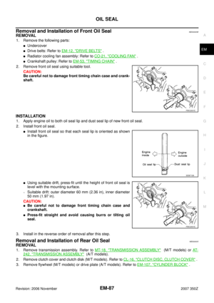 87
87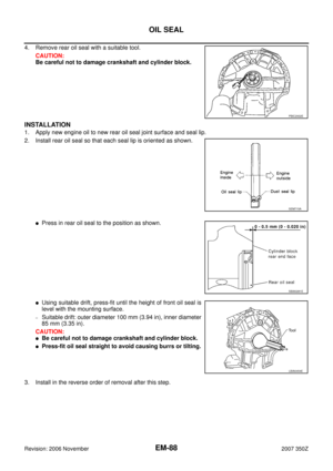 88
88 89
89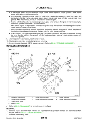 90
90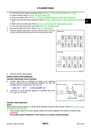 91
91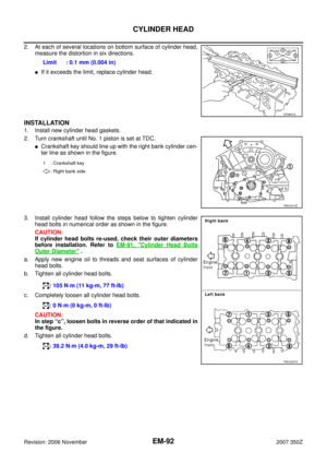 92
92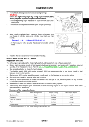 93
93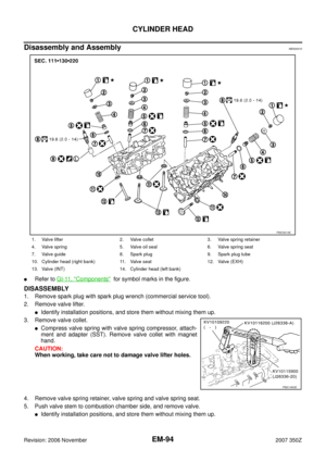 94
94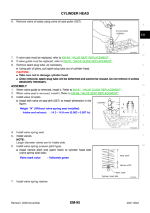 95
95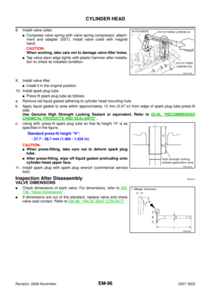 96
96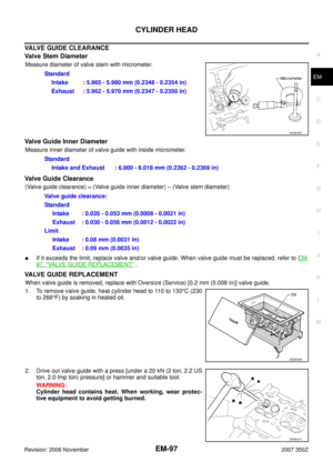 97
97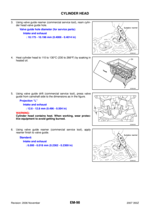 98
98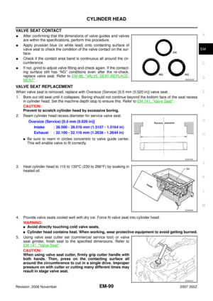 99
99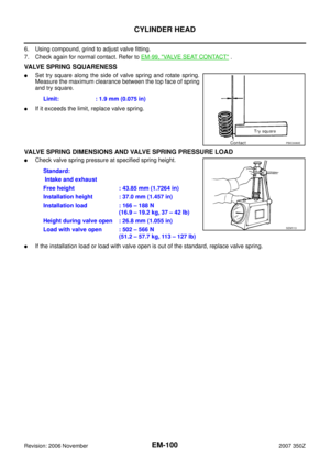 100
100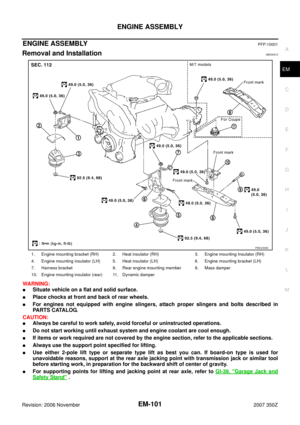 101
101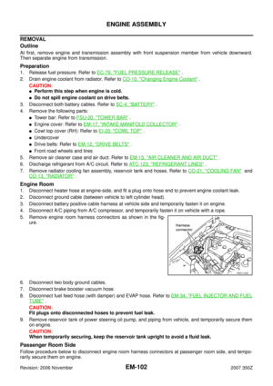 102
102 103
103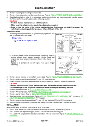 104
104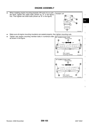 105
105 106
106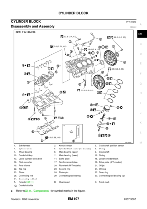 107
107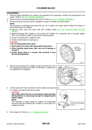 108
108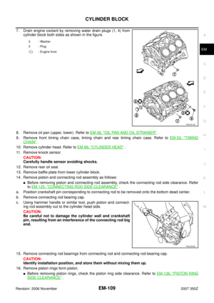 109
109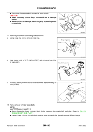 110
110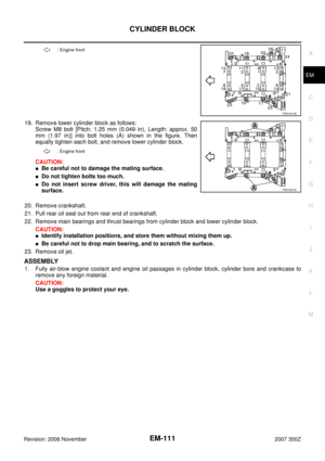 111
111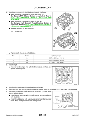 112
112 113
113 114
114 115
115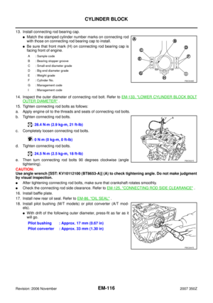 116
116 117
117 118
118 119
119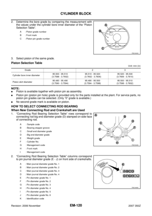 120
120 121
121 122
122 123
123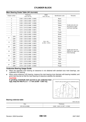 124
124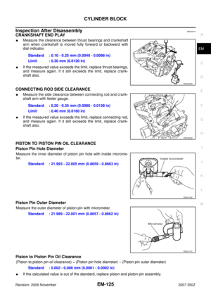 125
125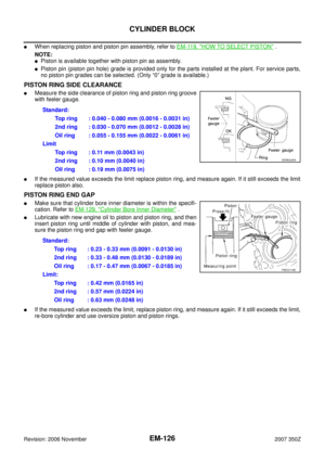 126
126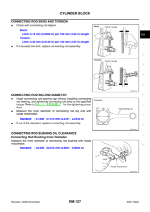 127
127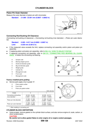 128
128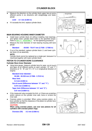 129
129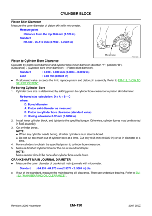 130
130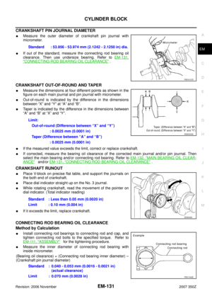 131
131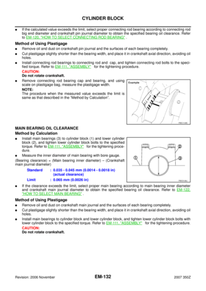 132
132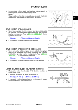 133
133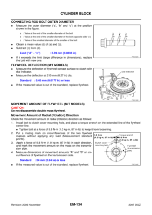 134
134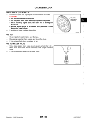 135
135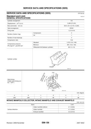 136
136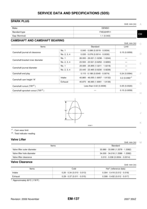 137
137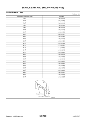 138
138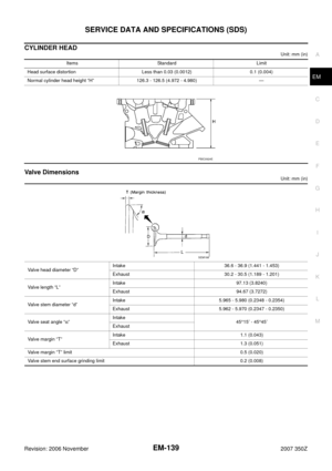 139
139 140
140 141
141 142
142 143
143 144
144 145
145 146
146 147
147