Page 129 of 148

CYLINDER BLOCK
EM-129
C
D
E
F
G
H
I
J
K
L
MA
EM
Revision: 2006 November2007 350Z
�Measure the distortion on the cylinder block upper face at some
different points in six directions with straightedge and feeler
gauge.
�If it exceeds the limit, replace cylinder block.
MAIN BEARING HOUSING INNER DIAMETER
�Install lower cylinder block (2) without installing main bearings,
and tighten lower cylinder block bolts to the specified torque.
Refer to E M - 111 , "
ASSEMBLY" for the tightening procedure.
�Measure the inner diameter of main bearing housing with bore
gauge.
�If out of the standard, replace cylinder block (1) and lower cylin-
der block (2) as assembly.
NOTE:
Cylinder block cannot be replaced as a single part, because it is
machined together with lower cylinder block.
PISTON TO CYLINDER BORE CLEARANCE
Cylinder Bore Inner Diameter
�Using bore gauge, measure cylinder bore for wear, out-of-round
and taper at six different points on each cylinder. (“X” and “Y”
directions at “A”, “B” and “C”) (“X” is in longitudinal direction of
engine)
�If the measured value exceeds the limit, or if there are scratches
and/or seizure on the cylinder inner wall, hone or re-bore the
inner wall.
�Oversize piston is provided. When using oversize piston, re-
bore cylinder so that the clearance of the piston-to-cylinder bore
satisfies the standard.
CAUTION:
When using oversize piston, use over size pistons for all
cylinders with oversize piston rings.Limit : 0.1 mm (0.004 in)
SEM123C
Standard : 69.993 - 70.017 mm (2.7556 - 2.7566 in)
PBIC5125J
Standard inner diameter:
95.500 - 95.530 mm (3.7598 - 3.7610 in)
Wear limit:
0.2 mm (0.008 in)
Out-of-round (Difference between “X” and “Y”):
0.015 mm (0.0006 in)
Taper limit (Difference between “A” and “C”):
0.01 mm (0.0004 in)
Oversize (OS) : 0.2 mm (0.008 in)
PBIC0923E
SEM843E
Page 130 of 148

EM-130
CYLINDER BLOCK
Revision: 2006 November2007 350Z
Piston Skirt Diameter
Measure the outer diameter of piston skirt with micrometer.
Piston to Cylinder Bore Clearance
Calculate by piston skirt diameter and cylinder bore inner diameter (direction “Y”, position “B”).
(Clearance) = (Cylinder bore inner diameter) – (Piston skirt diameter).
�If calculated value exceeds the limit, replace piston and piston pin assembly. Refer to EM-119, "HOW TO
SELECT PISTON" .
Re-boring Cylinder Bore
1. Cylinder bore size is determined by adding piston to cylinder bore clearance to piston skirt diameter.
2. Install lower cylinder block, and tighten to the specified torque. Otherwise, cylinder bores may be distorted
in final assembly.
3. Cut cylinder bores.
NOTE:
�When any cylinder needs boring, all other cylinders must also be bored.
�Do not cut too much out of cylinder bore at a time. Cut only 0.05 mm (0.0020 in) or so in diameter at a
time.
4. Hone cylinders to obtain the specified piston to cylinder bore clearance.
5. Measure finished cylinder bore for the out-of-round and taper.
NOTE:
Measurement should be done after cylinder bore cools down.
CRANKSHAFT MAIN JOURNAL DIAMETER
�Measure the outer diameter of crankshaft main journals with micrometer.
�If out of the standard, measure the main bearing oil clearance. Then use undersize bearing. Refer to EM-
132, "MAIN BEARING OIL CLEARANCE" . Measure point
: Distance from the top 38.8 mm (1.528 in)
Standard
: 95.480 - 95.510 mm (3.7590 - 3.7602 in)
PBIC0125E
Standard : 0.010 - 0.030 mm (0.0004 - 0.0012 in)
Limit : 0.08 mm (0.0031 in)
Re-bored size calculation: D = A + B – C
where,
D: Bored diameter
A: Piston skirt diameter as measured
B: Piston to cylinder bore clearance (standard value)
C: Honing allowance 0.02 mm (0.0008 in)
Standard : 64.951 - 64.975 mm (2.5571 - 2.5581 in) dia.
Page 131 of 148

CYLINDER BLOCK
EM-131
C
D
E
F
G
H
I
J
K
L
MA
EM
Revision: 2006 November2007 350Z
CRANKSHAFT PIN JOURNAL DIAMETER
�Measure the outer diameter of crankshaft pin journal with
micrometer.
�If out of the standard, measure the connecting rod bearing oil
clearance. Then use undersize bearing. Refer to EM-131,
"CONNECTING ROD BEARING OIL CLEARANCE" .
CRANKSHAFT OUT-OF-ROUND AND TAPER
�Measure the dimensions at four different points as shown in the
figure on each main journal and pin journal with micrometer.
�Out-of-round is indicated by the difference in the dimensions
between “X” and “Y” at “A” and “B”.
�Taper is indicated by the difference in the dimensions between
“A” and “B” at “X” and “Y”.
�If the measured value exceeds the limit, correct or replace crankshaft.
�If corrected, measure the bearing oil clearance of the corrected main journal and/or pin journal. Then
select the main bearing and/or connecting rod bearing. Refer to EM-132, "
MAIN BEARING OIL CLEAR-
ANCE" and/or EM-131, "CONNECTING ROD BEARING OIL CLEARANCE" .
CRANKSHAFT RUNOUT
�Place V-block on precise flat table, and support the journals on
the both end of crankshaft.
�Place dial indicator straight up on the No. 3 journal.
�While rotating crankshaft, read the movement of the pointer on
dial indicator. (Total indicator reading)
�If it exceeds the limit, replace crankshaft.
CONNECTING ROD BEARING OIL CLEARANCE
Method by Calculation
�Install connecting rod bearings to connecting rod and cap, and
tighten connecting rod bolts to the specified torque. Refer to
E M - 111 , "
ASSEMBLY" for the tightening procedure.
�Measure the inner diameter of connecting rod bearing with
inside micrometer.
(Bearing oil clearance) = (Connecting rod bearing inner diameter) –
(Crankshaft pin journal diameter)Standard : 53.956 - 53.974 mm (2.1242 - 2.1250 in) dia.
PBIC0127E
Limit:
Out-of-round (Difference between “X” and “Y”)
: 0.0025 mm (0.0001 in)
Taper (Difference between “A” and “B”)
: 0.0025 mm (0.0001 in)
SBIA0535E
Standard : Less than 0.05 mm (0.0020 in)
Limit : 0.10 mm (0.004 in)
SEM346D
Standard : 0.040 - 0.053 mm (0.0016 - 0.0021 in)
(actual clearance)
Limit : 0.070 mm (0.0028 in)
PBIC1642E
Page 132 of 148

EM-132
CYLINDER BLOCK
Revision: 2006 November2007 350Z
�If the calculated value exceeds the limit, select proper connecting rod bearing according to connecting rod
big end diameter and crankshaft pin journal diameter to obtain the specified bearing oil clearance. Refer
to EM-120, "
HOW TO SELECT CONNECTING ROD BEARING" .
Method of Using Plastigage
�Remove oil and dust on crankshaft pin journal and the surfaces of each bearing completely.
�Cut plastigage slightly shorter than the bearing width, and place it in crankshaft axial direction, avoiding oil
holes.
�Install connecting rod bearings to connecting rod and cap, and tighten connecting rod bolts to the speci-
fied torque. Refer to E M - 111 , "
ASSEMBLY" for the tightening procedure.
CAUTION:
Do not rotate crankshaft.
�Remove connecting rod bearing cap and bearing, and using
scale on plastigage bag, measure the plastigage width.
NOTE:
The procedure when the measured value exceeds the limit is
same as that described in the “Method by Calculation”.
MAIN BEARING OIL CLEARANCE
Method by Calculation
�Install main bearings (3) to cylinder block (1) and lower cylinder
block (2), and tighten lower cylinder block bolts to the specified
torque. Refer to EM-111, "
ASSEMBLY" for the tightening proce-
dure.
�Measure the inner diameter of main bearing with bore gauge.
(Bearing clearance) = (Main bearing inner diameter) – (Crankshaft
main journal diameter)
�If the clearance exceeds the limit, select proper main bearing according to main bearing inner diameter
and crankshaft main journal diameter to obtain the specified bearing oil clearance. Refer to EM-122,
"HOW TO SELECT MAIN BEARING" .
Method of Using Plastigage
�Remove oil and dust on crankshaft main journal and the surfaces of each bearing completely.
�Cut plastigage slightly shorter than the bearing width, and place it in crankshaft axial direction, avoiding oil
holes.
�Install main bearings to cylinder block and lower cylinder block, and tighten lower cylinder block bolts with
lower cylinder block to the specified torque. Refer to E M - 111 , "
ASSEMBLY" for the tightening procedure.
CAUTION:
Do not rotate crankshaft.
PBIC1149E
Standard : 0.035 - 0.045 mm (0.0014 - 0.0018 in)
(actual clearance)
Limit : 0.065 mm (0.0026 in)
PBIC5126J
Page 133 of 148

CYLINDER BLOCK
EM-133
C
D
E
F
G
H
I
J
K
L
MA
EM
Revision: 2006 November2007 350Z
�Remove lower cylinder block and bearings, and using scale on
plastigage bag, measure the plastigage width.
NOTE:
The procedure when the measured value exceeds the limit is
same as that described in the “Method by Calculation”.
CRUSH HEIGHT OF MAIN BEARING
�When lower cylinder block is removed after being tightened to
the specified torque with main bearings installed, the tip end of
bearing must protrude. Refer to E M - 111 , "
ASSEMBLY" for the
tightening procedure.
�If the standard is not met, replace main bearings.
CRUSH HEIGHT OF CONNECTING ROD BEARING
�When connecting rod bearing cap is removed after being tight-
ened to the specified torque with connecting rod bearings
installed, the tip end of bearing must protrude. Refer to E M - 111 ,
"ASSEMBLY" for the tightening procedure.
�If the standard is not met, replace connecting rod bearings.
LOWER CYLINDER BLOCK BOLT OUTER DIAMETER
�Measure the outer diameters (“d1 ”, “d2 ”) at two positions as
shown in the figure.
�If reduction appears in “A” range, regard it as “d2 ”.
�If it exceeds the limit (large difference in dimensions), replace
lower cylinder block bolt with new one.
PBIC1149E
Standard : There must be crush height.
SEM502G
Standard : There must be crush height.
PBIC1646E
Limit (“d1 ” – “d2 ”) : 0.11 mm (0.0043 in)
PBIC0911E
Page 134 of 148
 at the position
shown in the figure.
�Obtain a mean")
EM-134
CYLINDER BLOCK
Revision: 2006 November2007 350Z
CONNECTING ROD BOLT OUTER DIAMETER
�Measure the outer diameter (“a”, “b” and “c”) at the position
shown in the figure.
�Obtain a mean value (d) of (a) and (b).
�Subtract (c) from (d).
�If it exceeds the limit (large difference in dimensions), replace
the bolt with new one.
FLYWHEEL DEFLECTION (M/T MODELS)
�Measure the deflection of flywheel contact surface to clutch with
dial indicator.
�Measure the deflection at 210 mm (8.27 in) dia.
�If the measured value is out of the standard, replace flywheel.
MOVEMENT AMOUNT OF FLYWHEEL (M/T MODELS)
CAUTION:
Do not disassemble double mass flywheel.
Movement Amount of Radial (Rotation) Direction
Check the movement amount of radial (rotation) direction as follows:
1. Install bolt to clutch cover mounting hole, and place a torque wrench on the extended line of the flywheel
center line.
�Tighten bolt at a force of 9.8 N·m (1.0 kg-m, 87 in-lb) to keep it from loosening.
2. Put a mating mark on circumferences of the two flywheel
masses without applying any load (Measurement standard
points).
3. Apply a force of 9.8 N·m (1.0 kg-m, 87 in-lb) in each direction,
and mark the movement amount on the mass on the transmis-
sion side.
4. Measure dimensions of movement amounts “A” and “B” on cir-
cumference of flywheel on the transmission side.
�If the measured value is out of the standard, replace flywheel.
a : Value at the end of the smaller diameter of the bolt
b : Value at the end of the smaller diameter of the bolt (opposite side “a”)
c : Value of the smallest diameter of the smaller of the bolt
Limit (“d” − “c”) : 0.09 mm (0.0035 in)
PBIC5025E
Standard : 0.45 mm (0.0177 in) or less
PBIC2168E
Standard : 24 mm (0.94 in) or less
PBIC1046E
Page 135 of 148
CYLINDER BLOCK
EM-135
C
D
E
F
G
H
I
J
K
L
MA
EM
Revision: 2006 November2007 350Z
DRIVE PLATE (A/T MODELS)
�Check drive plate and signal plate for deformation or cracks.
CAUTION:
�Do not disassemble drive plate.
�Do not place drive plate with signal plate facing down.
�When handling signal plate, take care not to damage or
scratch it.
�Handle signal plate in a manner that prevents it from
becoming magnetized.
�If anything is found, replace drive plate.
OIL JET
�Check nozzle for deformation and damage.
�Blow compressed air from nozzle, and check for clogs.
�If it is not satisfied, clean or replace oil jet.
OIL JET RELIEF VALVE
�Using clean plastic stick, press check valve in oil jet relief valve.
Make sure that valve moves smoothly with proper reaction
force.
�If it is not satisfied, replace oil jet relief valve.
SEM760G
EMU0468D
Page 136 of 148
EM-136
SERVICE DATA AND SPECIFICATIONS (SDS)
Revision: 2006 November2007 350Z
SERVICE DATA AND SPECIFICATIONS (SDS)PFP:00100
Standard and LimitNBS00016
GENERAL SPECIFICATIONS
INTAKE MANIFOLD COLLECTOR, INTAKE MANIFOLD AND EXHAUST MANIFOLD
Unit: mm (in) Cylinder arrangementV-6
Displacement cm
3 (cu in)3,498 (213.45)
Bore and stroke mm (in)95.5 x 81.4 (3.76 x 3.205)
Valve arrangementDOHC
Firing order1-2-3-4-5-6
Number of piston ringsCompression 2
Oil 1
Number of main bearings4
Compression ratio10.6
Compression pressure
kPa (kg/cm
2 , psi)/300 rpmStandard 1,275 (13.0, 185)
Minimum 981 (10.0, 142)
Differential limit between cylinders 98 (1.0, 14)
Cylinder number
Va l v e t i m i n g
(Intake valve timing con-
trol - “OFF”)
Unit: degree
abcdef
248 248 2 66 0 68
SEM713A
PBIC0187E
Items Limit
Surface distortionIntake manifold collector 0.1 (0.004)
Intake manifold 0.1 (0.004)
Exhaust manifold 0.3 (0.012)
 1
1 2
2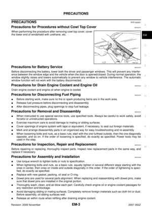 3
3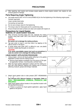 4
4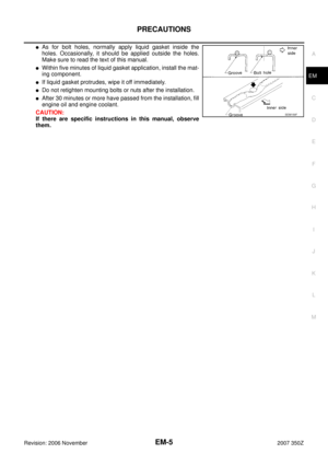 5
5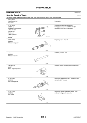 6
6 7
7 8
8 9
9 10
10 11
11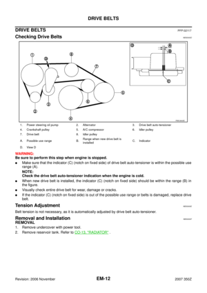 12
12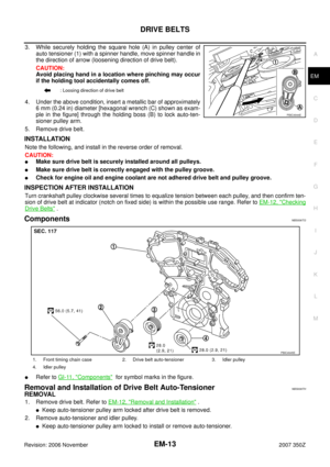 13
13 14
14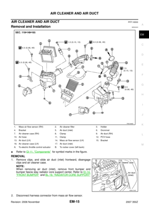 15
15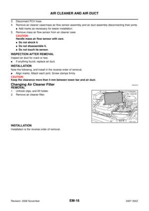 16
16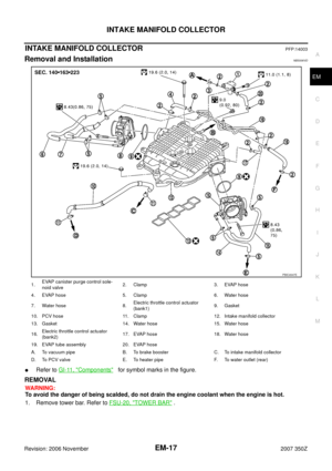 17
17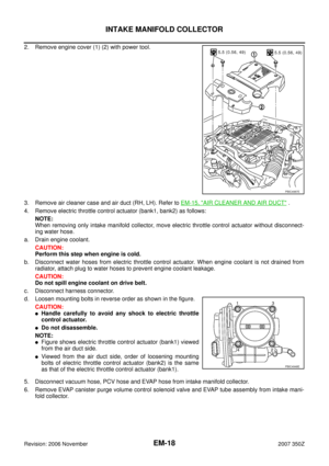 18
18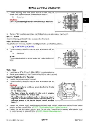 19
19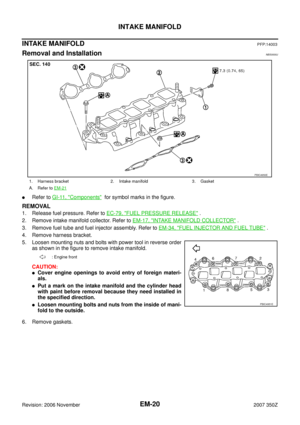 20
20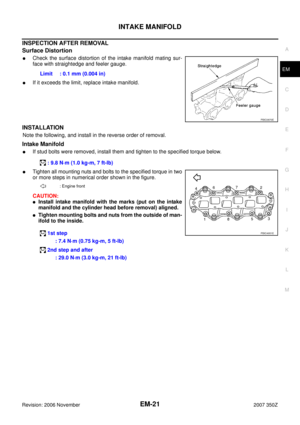 21
21 22
22 23
23 24
24 25
25 26
26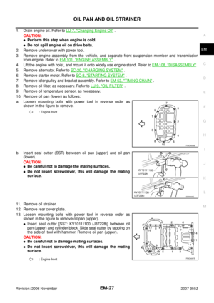 27
27 28
28 29
29 30
30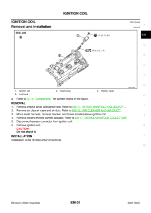 31
31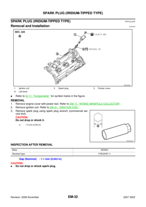 32
32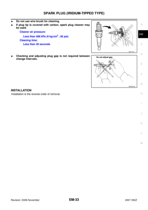 33
33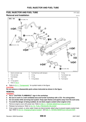 34
34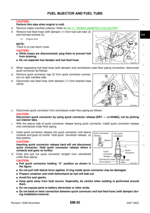 35
35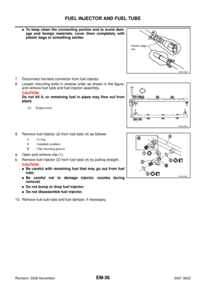 36
36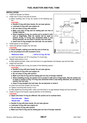 37
37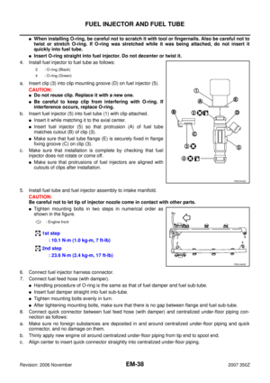 38
38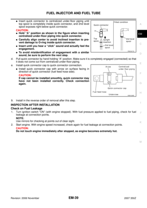 39
39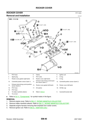 40
40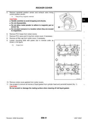 41
41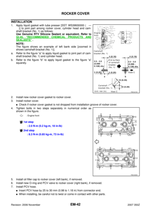 42
42 43
43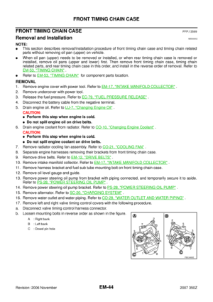 44
44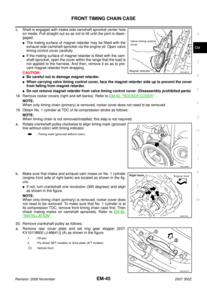 45
45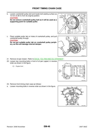 46
46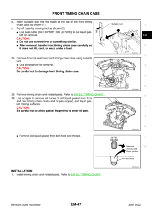 47
47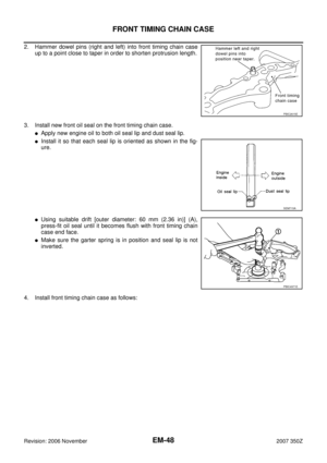 48
48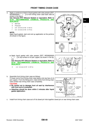 49
49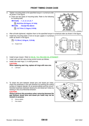 50
50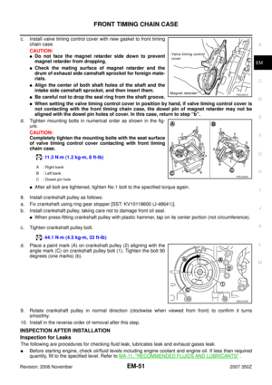 51
51 52
52 53
53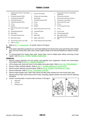 54
54 55
55 56
56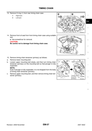 57
57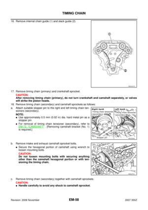 58
58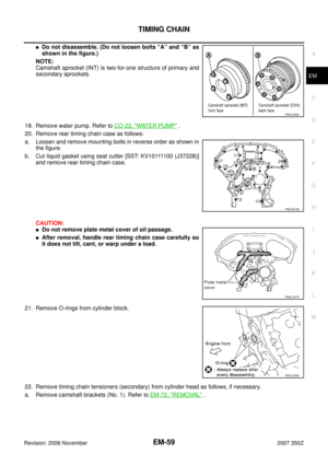 59
59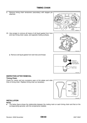 60
60 61
61 62
62 63
63 64
64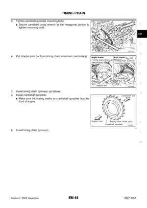 65
65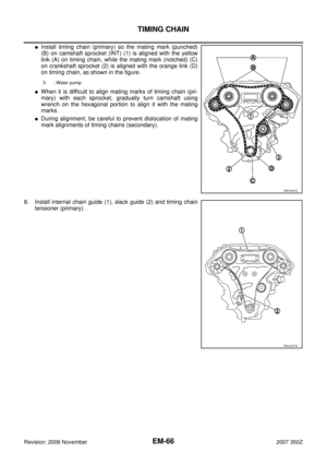 66
66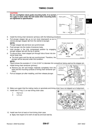 67
67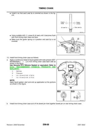 68
68 69
69 70
70 71
71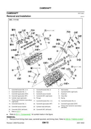 72
72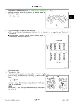 73
73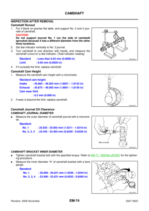 74
74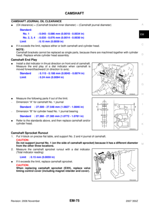 75
75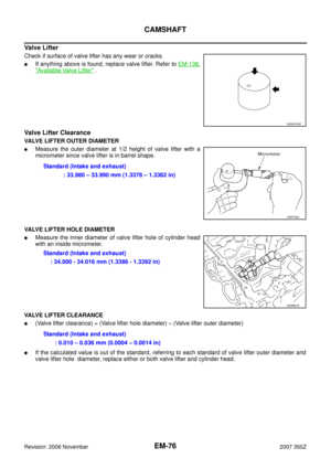 76
76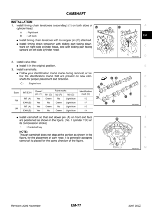 77
77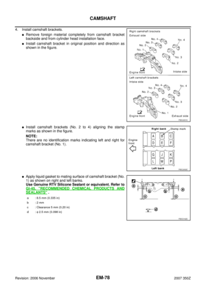 78
78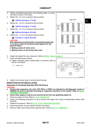 79
79 80
80 81
81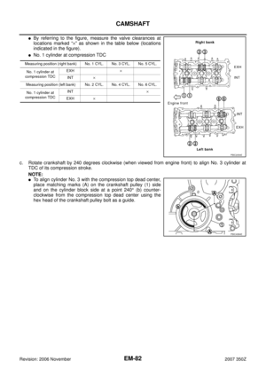 82
82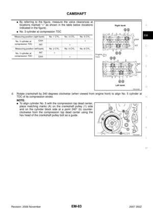 83
83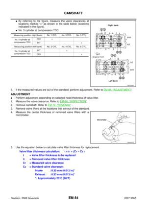 84
84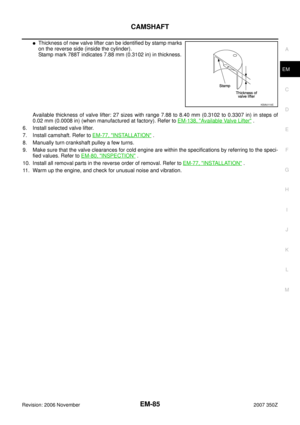 85
85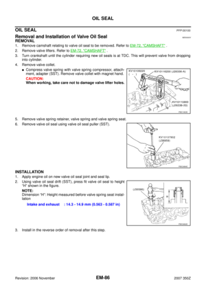 86
86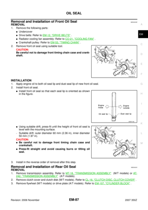 87
87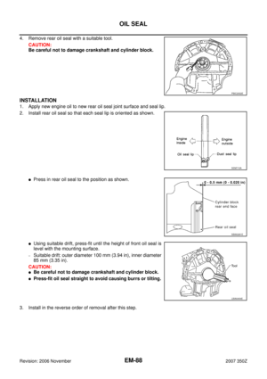 88
88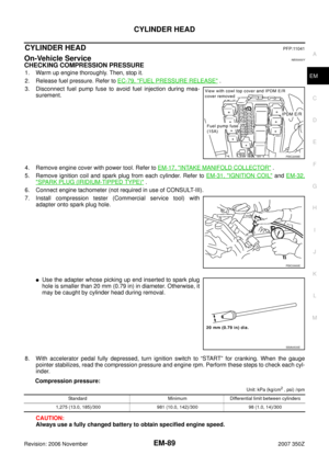 89
89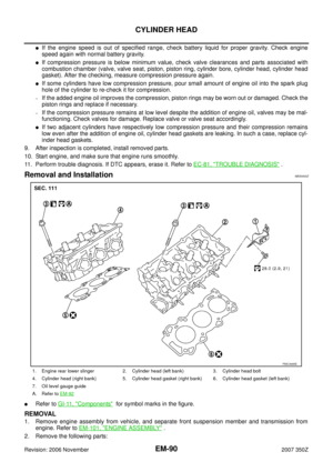 90
90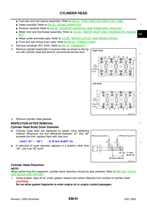 91
91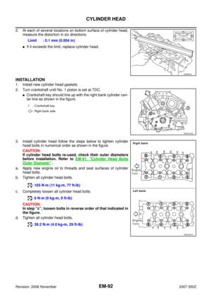 92
92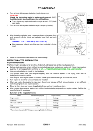 93
93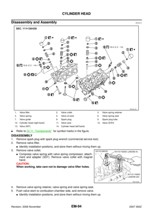 94
94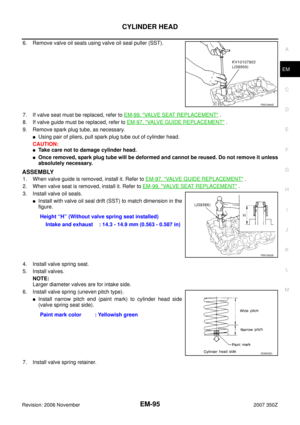 95
95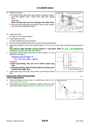 96
96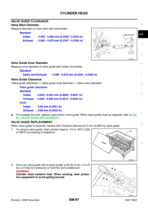 97
97 98
98 99
99 100
100 101
101 102
102 103
103 104
104 105
105 106
106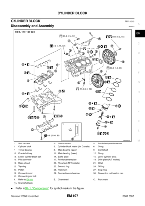 107
107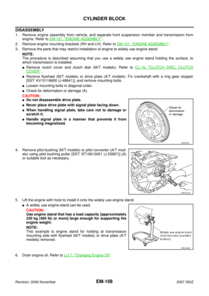 108
108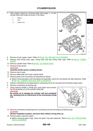 109
109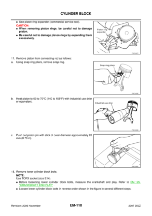 110
110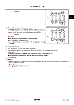 111
111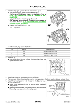 112
112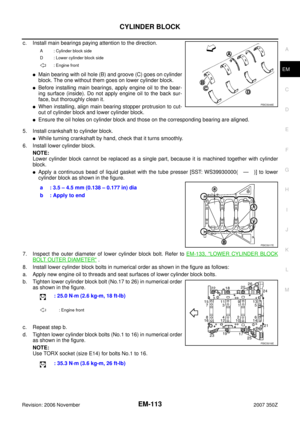 113
113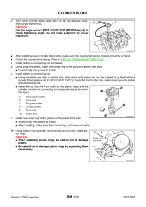 114
114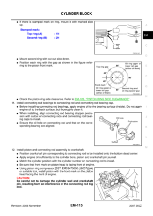 115
115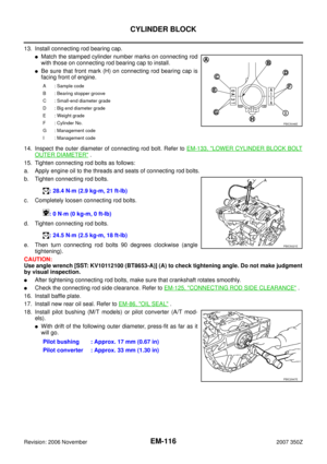 116
116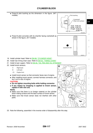 117
117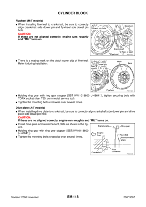 118
118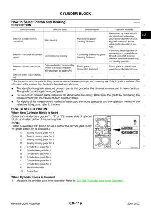 119
119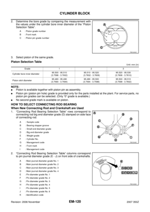 120
120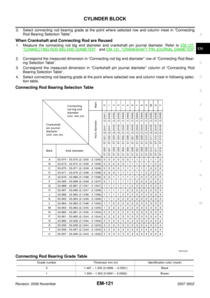 121
121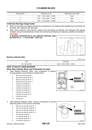 122
122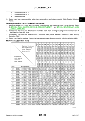 123
123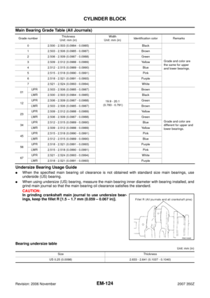 124
124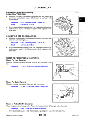 125
125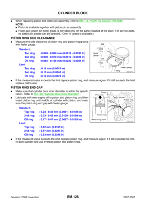 126
126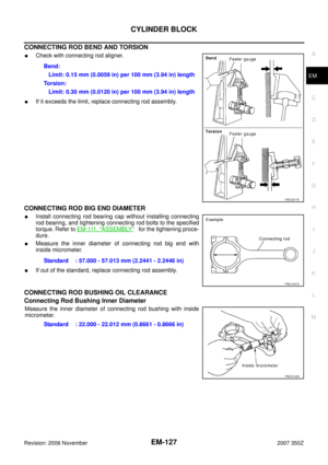 127
127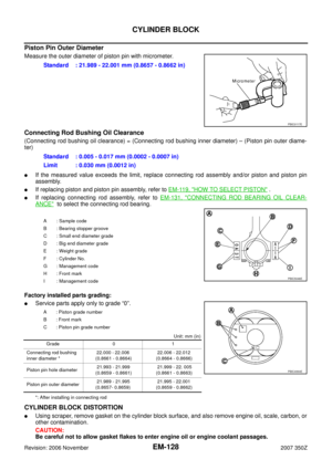 128
128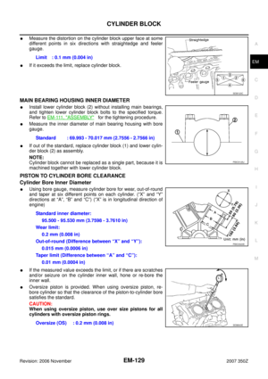 129
129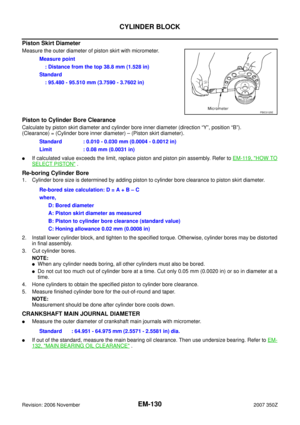 130
130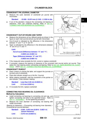 131
131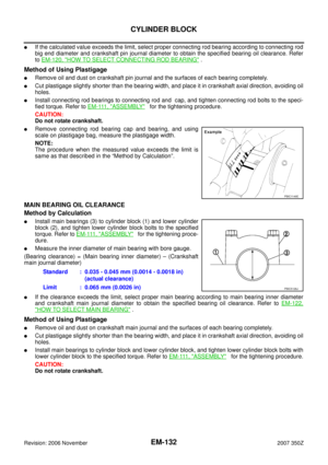 132
132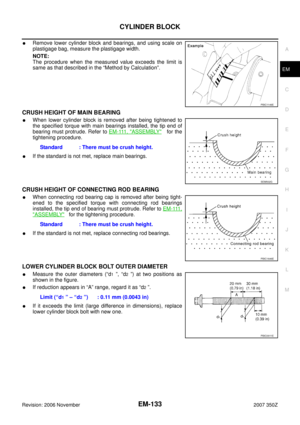 133
133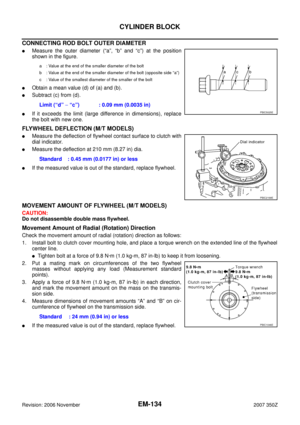 134
134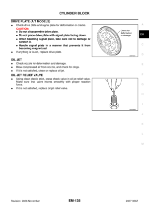 135
135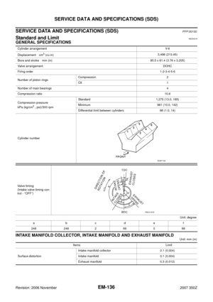 136
136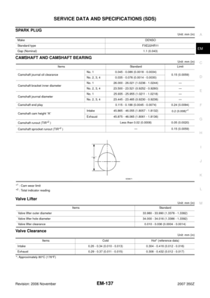 137
137 138
138 139
139 140
140 141
141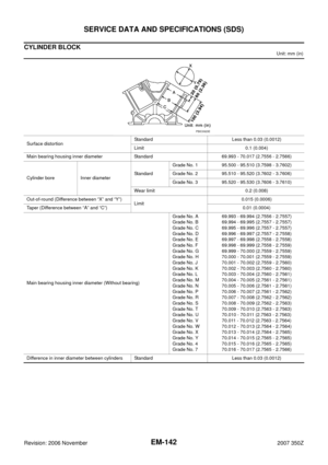 142
142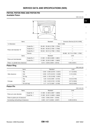 143
143 144
144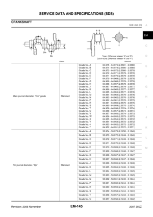 145
145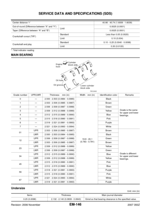 146
146 147
147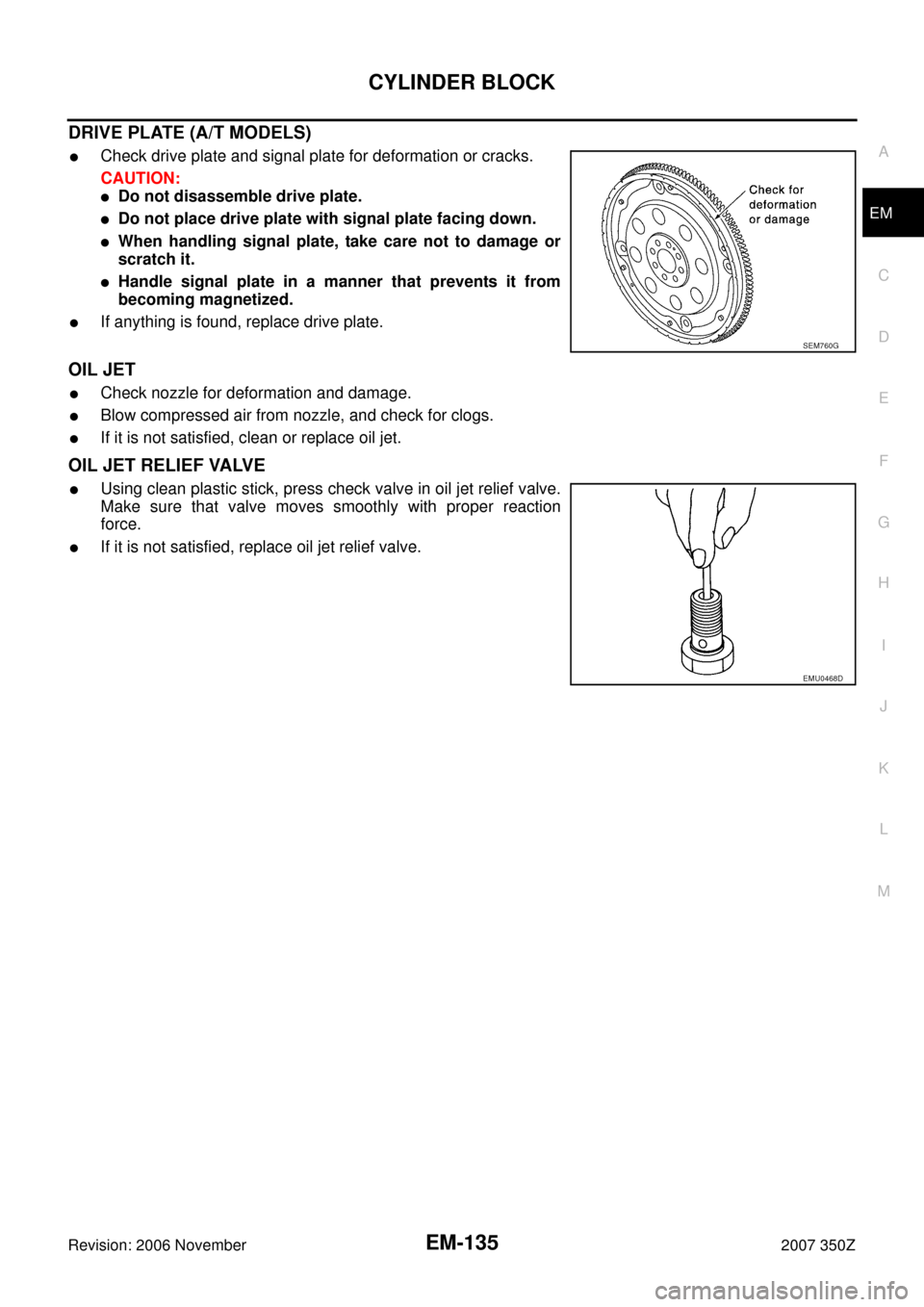

Revision: 2006 November2007 350Z
SERVICE DATA AND SPECIFICATIONS (SDS)PFP:00100
Standard and LimitNBS00016
GENERAL SPECIFICATIONS
INTAKE MANIFOLD COLLECTOR")