2007 NISSAN 350Z Engine Mechanical Workshop Manual
-
 1
1 -
 2
2 -
 3
3 -
 4
4 -
 5
5 -
 6
6 -
 7
7 -
 8
8 -
 9
9 -
 10
10 -
 11
11 -
 12
12 -
 13
13 -
 14
14 -
 15
15 -
 16
16 -
 17
17 -
 18
18 -
 19
19 -
 20
20 -
 21
21 -
 22
22 -
 23
23 -
 24
24 -
 25
25 -
 26
26 -
 27
27 -
 28
28 -
 29
29 -
 30
30 -
 31
31 -
 32
32 -
 33
33 -
 34
34 -
 35
35 -
 36
36 -
 37
37 -
 38
38 -
 39
39 -
 40
40 -
 41
41 -
 42
42 -
 43
43 -
 44
44 -
 45
45 -
 46
46 -
 47
47 -
 48
48 -
 49
49 -
 50
50 -
 51
51 -
 52
52 -
 53
53 -
 54
54 -
 55
55 -
 56
56 -
 57
57 -
 58
58 -
 59
59 -
 60
60 -
 61
61 -
 62
62 -
 63
63 -
 64
64 -
 65
65 -
 66
66 -
 67
67 -
 68
68 -
 69
69 -
 70
70 -
 71
71 -
 72
72 -
 73
73 -
 74
74 -
 75
75 -
 76
76 -
 77
77 -
 78
78 -
 79
79 -
 80
80 -
 81
81 -
 82
82 -
 83
83 -
 84
84 -
 85
85 -
 86
86 -
 87
87 -
 88
88 -
 89
89 -
 90
90 -
 91
91 -
 92
92 -
 93
93 -
 94
94 -
 95
95 -
 96
96 -
 97
97 -
 98
98 -
 99
99 -
 100
100 -
 101
101 -
 102
102 -
 103
103 -
 104
104 -
 105
105 -
 106
106 -
 107
107 -
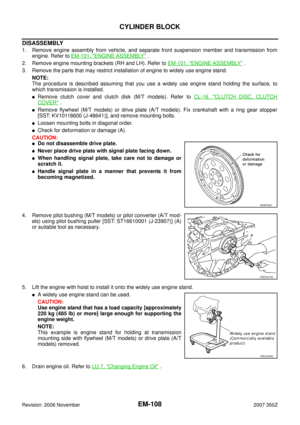 108
108 -
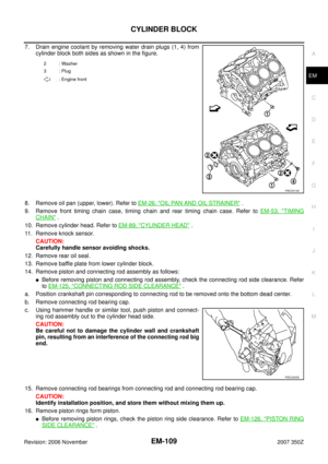 109
109 -
 110
110 -
 111
111 -
 112
112 -
 113
113 -
 114
114 -
 115
115 -
 116
116 -
 117
117 -
 118
118 -
 119
119 -
 120
120 -
 121
121 -
 122
122 -
 123
123 -
 124
124 -
 125
125 -
 126
126 -
 127
127 -
 128
128 -
 129
129 -
 130
130 -
 131
131 -
 132
132 -
 133
133 -
 134
134 -
 135
135 -
 136
136 -
 137
137 -
 138
138 -
 139
139 -
 140
140 -
 141
141 -
 142
142 -
 143
143 -
 144
144 -
 145
145 -
 146
146 -
 147
147
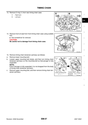
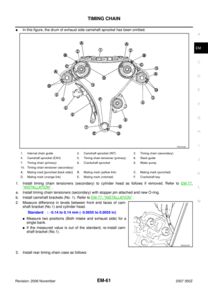
 from rear timing chain case.
14. Remove front oil seal from front timing chain case using suitable
t")
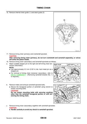
 and slack guide (2).
17. Remove timing chain (primary) and crankshaft sprocket.
CAUTION:
After removing timing c")

 with stopper pin
attached.
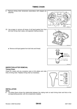
23. Use scraper to remove all traces of old liquid gasket from front
and re")
![NISSAN 350Z 2007 Z33 Engine Mechanical Workshop Manual EM-62
TIMING CHAIN
Revision: 2006 November2007 350Z
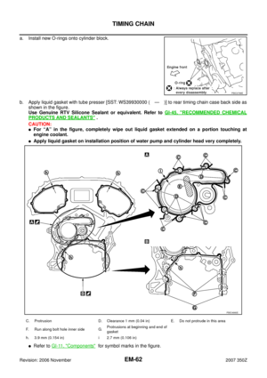
a. Install new O-rings onto cylinder block.
b. Apply liquid gasket with tube presser [SST: WS39930000 ( — )] to rear timing chain case back side a](/manual-img/5/765/w960_765-61.png "NISSAN 350Z 2007 Z33 Engine Mechanical Workshop Manual EM-62
TIMING CHAIN
Revision: 2006 November2007 350Z
a. Install new O-rings onto cylinder block.
b. Apply liquid gasket with tube presser [SST: WS39930000 ( — )] to rear timing chain case back side a")
 on cylinder block
and install rea")
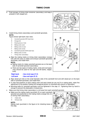
 and keep it
pressed in with stopper pin.
b. Install timing chains (secondary) and camshaft spr")