2006 LAND ROVER FRELANDER 2 lock
[x] Cancel search: lockPage 937 of 3229
Publi s hed: 11-May-2011
Engine Cooling - TD4 2.2L Diesel -
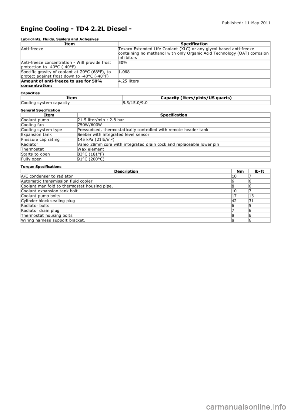
Lubricants, Fluids, Sealers and AdhesivesItemSpecification
Anti -freezeTexaco Ext ended Li fe Coolant (XLC) or any glycol bas ed anti -freezecontaini ng no met hanol wit h only Organic Acid Technology (O AT) corrosi oni nhi bit ors
Anti -freeze concentrati on - W i ll provi de frostprot ect ion to -40°C (-40°F)50%
Speci fi c gravit y of cool ant at 20°C (68°F), t oprot ect agains t fros t down to -40°C (-40°F)1.068
Amount of anti-freeze to use for 50%concentration:4.25 li ters
C apacitiesItemCapacity (liters/pints/US quarts)
Cooli ng sys t em capacit y8.5/15.0/9.0
General Specification
ItemSpecificationCoolant pump21.5 li ter/mi n : 2.8 bar
Cooli ng fan750W /600W
Cooli ng sys t em t ypePress uri s ed, t hermos tat icall y cont roll ed wi th remote header t ankExpans ion tankSeeber wit h int egrated level s ensor
Pres s ure cap rati ng145 kPa (21lb/i n²)
Radiat orVal eo 28mm core wit h i nt egrat ed drain cock and repl aceable l ower pi nThermos t atW ax element
St arts to open83°C (181°F)
Full y open91°C (200°C)
Torque Specifications
DescriptionNmlb-ftA/C condens er t o radiator107
Automat ic trans mi ss i on fl uid cooler66
Coolant manifold t o t hermos tat hous ing pipe.86Coolant expans ion t ank bol t107
Coolant pump bolt s1713
Cyli nder block s ealing pl ug4231Radiat or bolt s65
Radiat or drain pl ug76
Thermos t at hous ing bolt s86W iri ng harnes s s upport bracket .86
Page 940 of 3229
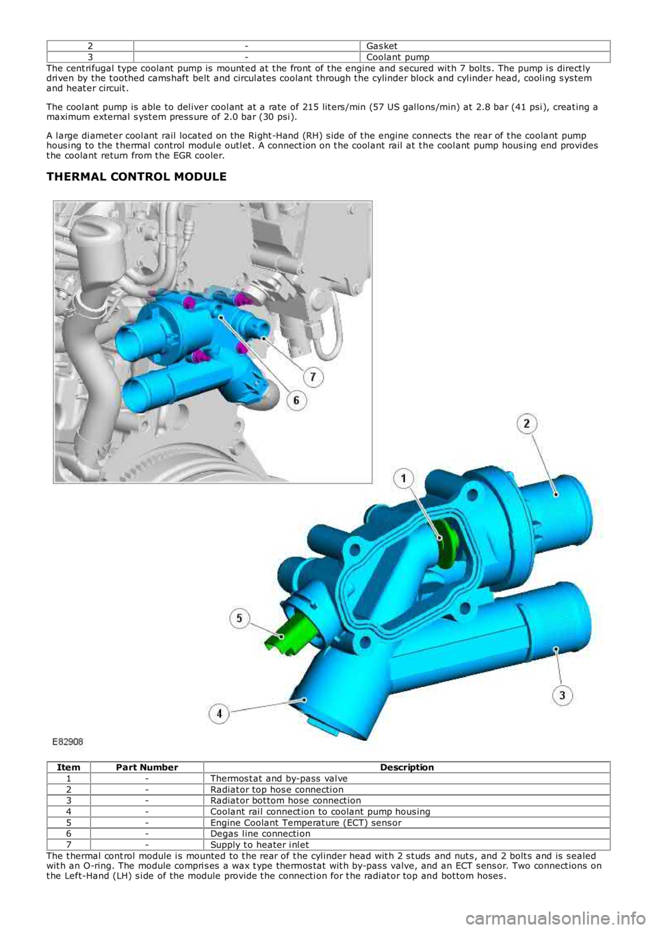
2-Gas ket
3-Coolant pump
The cent ri fugal type coolant pump is mount ed at t he front of t he engine and s ecured wit h 7 bol ts . The pump i s direct lydri ven by the t oothed cams haft belt and circul ates coolant through t he cylinder block and cyl inder head, cool ing s ys temand heat er circuit .
The cool ant pump is able to del iver cool ant at a rate of 215 lit ers /min (57 US gal lons /min) at 2.8 bar (41 psi ), creat ing amaximum external s yst em press ure of 2.0 bar (30 psi ).
A l arge di amet er cool ant rail located on the Ri ght -Hand (RH) s ide of t he engine connects the rear of t he coolant pumphous i ng to the t hermal control modul e outl et . A connect ion on t he cool ant rail at t he cool ant pump hous ing end provi dest he coolant return from t he EGR cooler.
THERMAL CONTROL MODULE
ItemPart NumberDescription
1-Thermos t at and by-pass val ve
2-Radiat or top hos e connecti on3-Radiat or bot tom hose connect ion
4-Coolant rai l connect ion to coolant pump hous ing
5-Engine Coolant Temperat ure (ECT) sens or6-Degas l ine connecti on
7-Supply t o heater i nl et
The t hermal cont rol module i s mounted to t he rear of t he cyl inder head wit h 2 s t uds and nut s , and 2 bolt s and is s ealedwit h an O-ring. The module compri s es a wax t ype thermos t at wit h by-pas s valve, and an ECT s ens or. Two connect ions ont he Left-Hand (LH) s i de of the module provide t he connecti on for t he radi at or top and bot tom hoses .
Page 943 of 3229
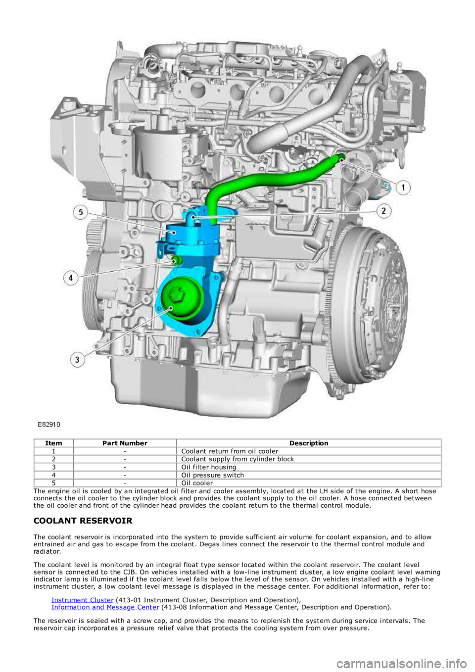
ItemPart NumberDescription
1-Cool ant return from oi l cool er2-Cool ant s upply from cyl inder block
3-Oil filt er hous i ng
4-Oil pres s ure s wi tch5-Oil cool er
The engi ne oil i s cool ed by an int egrated oi l fi lt er and cooler as sembl y, locat ed at t he LH s ide of t he engi ne. A s hort hoseconnects t he oil cooler t o the cyli nder bl ock and provi des the coolant s uppl y to the oi l cooler. A hos e connected bet weent he oil cool er and front of t he cyl inder head provi des the coolant ret urn t o t he t hermal cont rol module.
COOLANT RESERVOIR
The cool ant res ervoi r is incorporated into the s ys tem to provide s ufficient air volume for cool ant expansi on, and to al lowentrained air and gas t o es cape from the coolant . Degas l ines connect the res ervoir t o t he thermal control modul e andradi at or.
The cool ant l evel i s monit ored by an integral float t ype s ens or l ocat ed wit hin the coolant res ervoir. The cool ant l evels ens or is connect ed t o t he CJB. On vehicles ins tall ed wit h a low-line ins trument cl us t er, a l ow engine coolant level warningindicat or l amp i s il lumi nat ed if t he coolant level fall s below t he l evel of the s ensor. On vehicles i nst all ed wit h a hi gh-li neins t rument clus ter, a low coolant l evel mes sage i s dis played i n the mess age center. For addit ional i nformati on, refer to:
Ins trument Clus ter (413-01 Ins t rument Clus t er, Descripti on and Operat ion),Informat ion and Mes s age Cent er (413-08 Informati on and Mes sage Cent er, Descripti on and Operat ion).
The res ervoir i s s eal ed wi th a s crew cap, and provi des the means t o replenis h t he s ys t em duri ng s ervice i ntervals . Theres ervoir cap i ncorporat es a press ure rel ief val ve that prot ect s t he cool ing s ys tem from over pres sure.
Page 945 of 3229
ItemPart NumberDescription
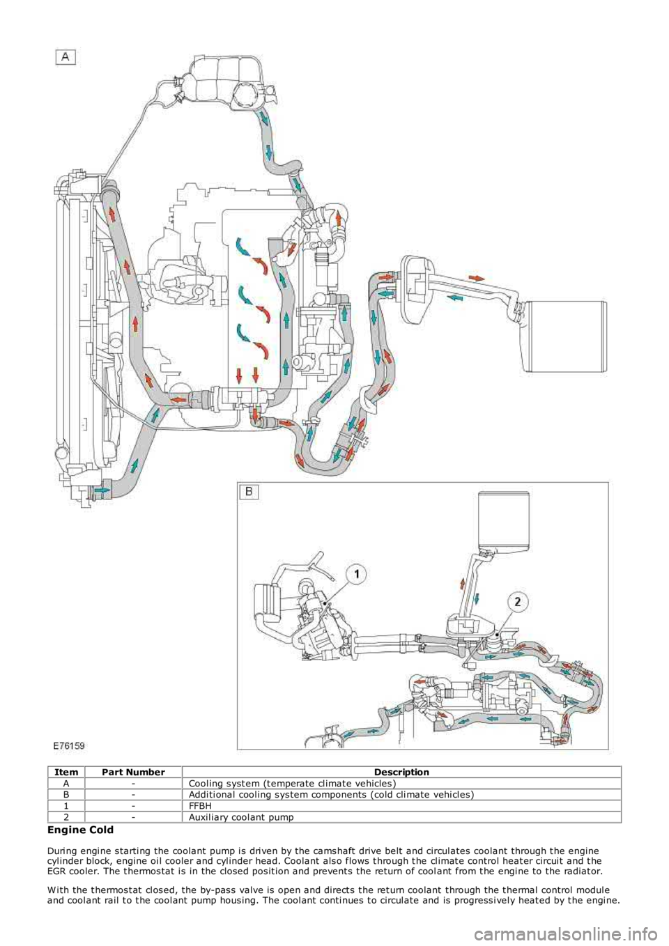
A-Cool ing s yst em (t emperate cl imat e vehicles )B-Addi ti onal cool ing s ys tem components (cold cli mate vehi cl es)
1-FFBH
2-Auxil iary cool ant pump
Engine Cold
Duri ng engi ne s tarti ng the coolant pump i s dri ven by the cams haft drive belt and circul ates coolant through t he enginecyl inder block, engine oi l cooler and cyl inder head. Coolant als o flows t hrough t he cl imat e control heat er circui t and t heEGR cooler. The t hermos tat i s in the cl os ed pos it ion and prevent s the return of coolant from t he engi ne to the radiat or.
W i th the t hermos t at cl os ed, the by-pas s valve is open and direct s t he ret urn coolant t hrough the t hermal control modul eand cool ant rail t o t he cool ant pump hous ing. The cool ant conti nues t o circul ate and is progress i vel y heat ed by t he engi ne.
Page 946 of 3229
Entrained gases i n t he cool ing s ys tem escape t hrough the t hermal control modul e degas l ine t o t he cool ant res ervoir.
The increas ing coolant temperature is felt at t he t hermos tat , and is regi s tered on the ins trument cl us t er coolantt emperature gage vi a t he ECM and ECT s ens or s i gnal.For addit ional informat ion, refer t o: Ins t rument Clus ter (413-01 Inst rument Cl us t er, Des cript ion and Operat ion).
Engine Normal Operating Temperature
W i th the coolant t emperature increas ing, at 83°C (181°F) t he t hermos tat reacts and commences openi ng. The by-pas svalve is progres s ively clos ed. Hot coolant ret urning from t he engi ne t o t he thermal control modul e i s now all owed to pas st hrough the t op hos e connecti on to the radiator. The fl ow of hot coolant t o t he radiat or now forces cold cool ant wi thi n t heradi at or and bot t om hos e t o fl ow t o t he thermal cont rol module.
Duri ng the thermos t at opening period t here i s an i nit ial temperat ure di fferenti al of t he coolant at bot h s ides of t het hermos tat . The thermos t at react s t o t he t emperature different ial and part iall y closes , whi le t he by-pas s val ve opensfurther. The thermos t at and by-pas s valve conti nue to oscil lat e whil e t he cool ant t emperat ure i ncreas es .
At a coolant temperat ure of 91°C (196°F) t he thermost at is full y opened and t he by-pas s valve i s ful ly clos ed. The returncool ant from t he engi ne is now ful ly circul ated t hrough t he radiat or and bot tom hose. Coolant flows t hrough the radiat orfrom the RH tank t o t he LH t ank, and i s cool ed by air pass i ng through the mat ri x. Ent rai ned gas es i n the radiat or es capet hrough the connect ed degas l ine t o t he cool ant res ervoir.
The increas ed cool ant volume created by heat expans ion caus es the coolant level to ri se through t he connecti ng res ervoirhose, and i nt o t he res ervoi r.
The t emperature of the cooli ng s ys t em i s cons t ant ly moni tored by t he ECM via the ECT s ens or s i gnal. The ECM uses t heECT s ignal to control operati on of the cooling fans , and to adjus t engine fueling. The ECM al so operates t he fans i nres ponse to input s from the aut omati c t ransmis s ion oil t emperat ure s ensor, Air Condit ioning (A/C) s ys tem cont rol s wit ch,and t he A/C pres sure s ens or. For addit ional i nformati on, refer to: El ect ronic Engine Cont rols - 2.2L Di es el (303-14Electroni c Engine Controls - 2.2L Dies el, Des cript ion and Operat ion).For addit ional informat ion, refer t o: Air Condit ioning (412-01 Cli mat e Cont rol , Descripti on and Operat ion).
The cool ing fan s peed is als o infl uenced by vehicle road s peed. The ECM adjus t s the speed of t he cool ing fans tocompens ate for t he ram air effect , us ing t he CAN bus road speed s ignal received from the Ant i-Lock Brake Sys tem (ABS)module.
W hen t he engine i s s hut down, t he coolant t emperature and volume decreas e. The thermos t at st art s t o clos e as t hecool ant t emperat ure decreas es to 89°C (192°F), and is fully cl osed at 81°C (178°F). The coolant level wit hin t he res ervoi rdecreas es as coolant is drawn from the res ervoi r to replenis h the s ys tem.
Followi ng engi ne s hut down when the coolant pump i s s tat ionary, the ECM may cont inue t o operat e t he cool ing fans for apre-det ermined peri od to maint ai n engine cooling.
Page 947 of 3229
Publi s hed: 11-May-2011
Engine Cooling - TD4 2.2L Diesel - Engine Cooling
Diagnosi s and Tes ti ng
Principles of Operation
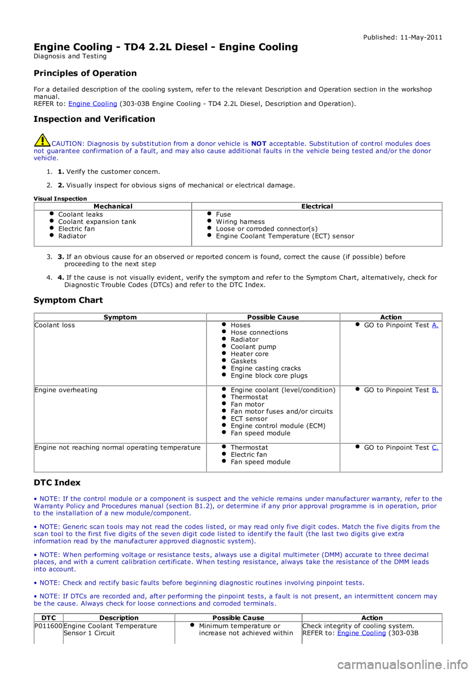
For a detail ed descripti on of the cooli ng s ys t em, refer t o t he rel evant Des cript ion and Operat ion secti on in the workshop
manual.
REFER to: Engine Cooli ng (303-03B Engi ne Cool ing - TD4 2.2L Dies el, Des cript ion and Operat ion).
Inspection and Verification CAUTION: Di agnos is by s ubs ti tut ion from a donor vehicle is
NO T acceptabl e. Subs ti tut ion of cont rol modules does
not guarant ee confirmat ion of a faul t, and may als o caus e addit ional fault s i n t he v ehi cl e being t est ed and/or t he donor
vehi cl e.
1. Verify t he cus t omer concern.
1.
2. Vis ually ins pect for obvious s igns of mechani cal or electrical damage.
2.
Visual Inspection Mechanical Electrical
Coolant leaks Coolant expans ion t ank
Electric fan
Radiat or Fuse
W i ri ng harness
Loos e or corroded connect or(s )
Engi ne Coolant Temperature (ECT) s ensor
3.
If an obvious cause for an obs erved or report ed concern is found, correct t he caus e (if pos s ible) before
proceeding t o t he next s t ep
3.
4. If t he caus e is not vis ually evi dent , verify t he sympt om and refer t o t he Sympt om Ch art, al ternat ively, check for
Di agnos ti c Trouble Codes (DTCs) and refer t o t he DTC Index.
4.
Symptom Chart Symptom Possible CauseAction
Coolant los s Hoses Hose connect ions
Radi ator
Cool ant pump
Heat er core
Gaskets
Engi ne cas t ing cracks
Engi ne block core plugs GO t o Pinpoint Test
A.Engine overheati ng
Engi ne cool ant (level/condit ion) Thermos tat
Fan motor
Fan motor fus es and/or circui ts
ECT s ens or
Engi ne cont rol module (ECM)
Fan speed module GO t o Pinpoint Test
B.Engine not reaching normal operat ing t emperat ure
Thermos tat Elect ric fan
Fan speed module GO t o Pinpoint Test
C.DTC Index
• NOTE: If the control modul e or a component i s s us pect and the vehicle remains unde r manufacturer warrant y, refer t o the
W arranty Pol icy and Procedures manual (s ect ion B1.2), or determine i f any pri or appr oval programme is in operat ion, pri or
t o the ins tall ati on of a new module/component.
• NOTE: Generic scan t ool s may not read the codes li st ed, or may read only fi ve digi t codes . Mat ch the five di git s from t he
s can tool to the firs t fi ve di git s of the seven digi t code l is ted to ident ify t he fa ul t (t he las t t wo digi ts gi ve ext ra
informat ion read by the manufact urer approved diagnos t ic s ys tem).
• NOTE: W hen performing volt age or res is t ance t est s , always use a digi tal mult imeter (DMM) accurat e t o t hree deci mal
places, and wi th a current cali brati on cert ifi cat e. W hen t est ing res is tance, al ways take t he res is t ance of t he DMM leads
int o account.
• NOTE: Check and recti fy bas ic faul ts before beginni ng diagnos t ic rout ines i nvol vi n g pinpoint t es t s.
• NOTE: If DTCs are recorded and, aft er performi ng the pi npoi nt tes ts , a fault is no t present , an int ermi tt ent concern may
be t he caus e. Always check for loose connect ions and corroded terminals .
DT C Description Possible Cause Action
P011600 Engine Coolant Temperat ure
Sensor 1 Circuit Mini mum temperat ure or
increas e not achi eved wi thi n Check int egrit y of cool ing s ys tem.
REFER t o: Engi ne Cool ing (303-03B
Page 949 of 3229
1
1
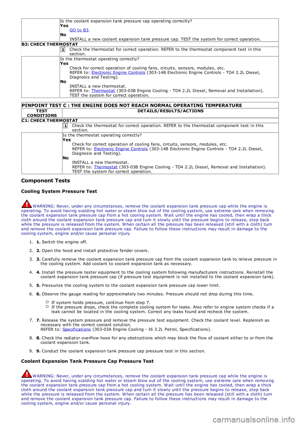
Is t he coolant expans ion t ank pres sure cap operati ng correctl y?
Yes GO t o B3 .
No INSTALL a new coolant expans ion t ank pres s ure cap. TEST t he s yst em for correct opera ti on.
B3: CHECK T HERMOST AT Check t he t hermos tat for correct operat ion. REFER to the t hermos t at component t es t i n t his
sect ion.
Is t he t hermos tat operat ing correct ly?
Yes
Check for correct operat ion of cooli ng fans , ci rcuit s , sens ors , modules , et c.
REFER t o: Electroni c Engine Controls (303-14B Electronic Engine Controls - TD4 2.2L Dies el,
Diagnos i s and Test ing).
No
INSTALL a new t hermos t at .
REFER t o: Thermos tat (303-03B Engine Cooli ng - TD4 2.2L Di esel , Removal and Ins t allat ion).
TEST the s ys tem for correct operat ion.
PINPOINT TEST C : THE ENG INE DOES NOT REACH NORMAL OPERATING TEMPERATURE T EST
CONDIT IONS DET AILS/RESULT S/ACT IONS
C1: CHECK T HERMOST AT Check t he thermost at for correct operat ion. REFER to t he t hermos tat component t est i n t his
secti on.
Is t he t hermos tat operati ng correct ly?
Yes Check for correct operat ion of cooling fans , ci rcuit s, s ens ors , modul es, et c.
REFER t o: Electroni c Engi ne Control s (303-14B Electroni c Engi ne Controls - TD4 2.2L Dies el,
Diagnos is and Tes t ing).
No INSTALL a new t hermos tat .
REFER t o: Thermos tat (303-03B Engi ne Cooling - TD4 2.2L Di es el, Removal and Ins t al lat ion).
TEST t he s yst em for correct operati on.
Component Tests
Cooling System Pressure Test W ARNING: Never, under any ci rcums tances, remove the coolant expans ion tank pres s ure
cap whi le t he engine i s
operati ng. To avoid havi ng s caldi ng hot water or s team bl ow out of the cooli ng s ys t e m, use ext reme care when removi ng
t he coolant expans ion tank pres s ure cap from a hot cool ing s ys tem. W ai t unti l the en gine has cooled, then wrap a t hick
cloth around t he coolant expans ion tank pres s ure cap and t urn it s lowl y unt il t he pr es s ure begins t o releas e, s t ep back
whil e t he pres sure i s rel eas ed from the s ys tem. W hen certai n all t he pres s ure has be en rel eas ed (s ti ll wit h a cl oth) t urn
and remove t he coolant expans ion t ank pres sure cap. Fail ure t o follow thes e i ns t ruct i ons may res ult i n damage t o t he
cool ing s ys tem, engine and/or cause pers onal injury.
1. Swit ch the engine off.
1.
2. Open the hood and i nst all prot ect ive fender covers .
2.
3. Careful ly remove the coolant expans ion t ank pres s ure cap from the coolant expans ion t ank to rel ieve pres s ure i n
t he cool ing s ys tem. Add coolant t o cool ant expans i on tank as necess ary.
3.
4. Ins t al l the press ure tes t er equipment t o t he cool ing s yst em foll owing manufact urers i nst ruct ions. Rei ns t all t he
coolant expans ion t ank pres sure cap (if pres s ure t est equipment i s not ins tal led t o t he cool ant expans i on tank).
4.
5. Pres surize t he cool ing s ys tem to the coolant expans ion t ank pres s ure cap lower l imi t .
5.
6. Observe the gauge readi ng for approximat ely t wo minutes . Pres s ure s houl d not drop du ring t his t ime.
If sys tem holds pres s ure, cont inue from s tep 7. If the pres s ure drops, check the complet e cool ing s ys tem for l eaks . Als o refer to en
gi ne s ys t em checks i f a
leak cannot be locat ed in the cooli ng s ys t em. Correct any leaks found and recheck t h e s ys t em.6.
7. Release the s ys tem pres s ure and remove the press ure tes t equipment. Check the coolan t level. Replenis h as
necess ary wit h t he correct cool ant s olut ion.
REFER t o: Specificati ons (303-03A Engine Cooli ng - I6 3.2L Pet rol, Specifi cat ions ).
7.
8. Check t he radi at or overfl ow hos e for any obs truct ions which may block the flow of co olant eit her to or from t he
coolant expans ion t ank.
8.
9. Conduct the coolant expans ion t ank pres s ure cap pres s ure t es t in t his secti on.
9.
Coolant Expansion Tank Pressure Cap Pressure Test W ARNING: Never, under any ci rcums tances, remove the coolant expans ion tank pres s ure
cap whi le t he engine i s
operati ng. To avoid havi ng s caldi ng hot water or s team bl ow out of the cooli ng s ys t e m, use ext reme care when removi ng
t he coolant expans ion tank pres s ure cap from a hot cool ing s ys tem. W ai t unti l the en gine has cooled, then wrap a t hick
cloth around t he coolant expans ion tank pres s ure cap and t urn it s lowl y unt il t he pr es s ure begins t o releas e, s t ep back
whil e t he pres sure i s rel eas ed from the s ys tem. W hen certai n all t he pres s ure has be en rel eas ed (s ti ll wit h a cl oth) t urn
and remove t he coolant expans ion t ank pres sure cap. Fail ure t o follow thes e i ns t ruct i ons may res ult i n damage t o t he
cool ing s ys tem, engine and/or cause pers onal injury.
Page 1001 of 3229
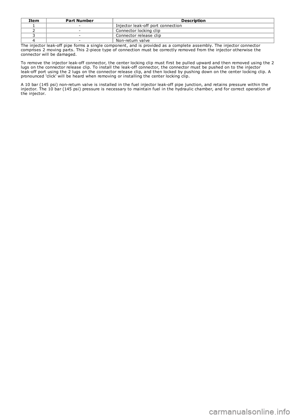
ItemPart NumberDescription
1-Inject or leak-off port connect ion
2-Connector l ocking cl ip3-Connector release cl ip
4-Non-ret urn val ve
The inject or leak-off pi pe forms a s i ngl e component , and is provi ded as a complete ass embly. The i nject or connect orcompris es 2 movi ng part s . Thi s 2-pi ece t ype of connect ion must be correctl y removed from the injector ot herwis e t heconnector wi ll be damaged.
To remove the i njector leak-off connect or, t he cent er locking cli p mus t fi rs t be pull ed upward and t hen removed us ing t he 2lugs on t he connector release cl ip. To i nst all t he leak-off connect or, t he connector mus t be pushed on to the i njectorleak-off port us ing t he 2 l ugs on the connect or releas e cli p, and t hen locked by pushi ng down on t he cent er l ocki ng cl ip. Apronounced 'cl ick' wi ll be heard when removing or i nst all ing t he cent er locki ng clip.
A 10 bar (145 psi ) non-ret urn val ve is i nst all ed in t he fuel i njector leak-off pipe junct ion, and ret ai ns pres s ure wi thi n theinject or. The 10 bar (145 ps i ) pres sure is neces sary to maint ain fuel i n t he hydraulic chamber, and for correct operat ion oft he inject or.