2006 LAND ROVER FRELANDER 2 lock
[x] Cancel search: lockPage 1131 of 3229
Publi s hed: 11-May-2011
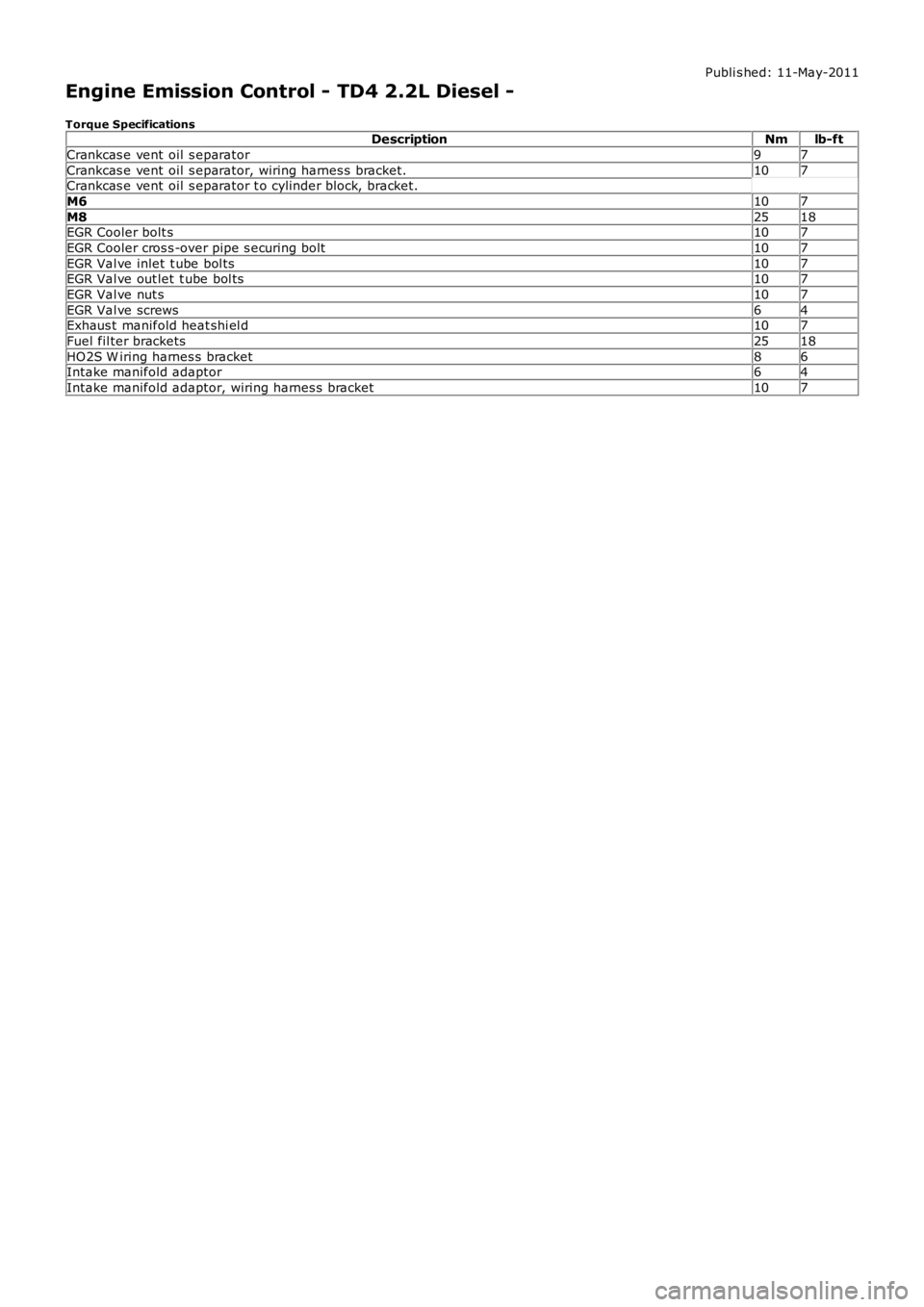
Engine Emission Control - TD4 2.2L Diesel -
Torque SpecificationsDescriptionNmlb-ft
Crankcas e vent oil s eparator97
Crankcas e vent oil s eparator, wiring harnes s bracket.107Crankcas e vent oil s eparator t o cylinder block, bracket.
M6107
M82518EGR Cooler bolt s107
EGR Cooler cros s -over pipe s ecuring bolt107
EGR Val ve inlet t ube bol ts107EGR Val ve out let t ube bol ts107
EGR Val ve nut s107
EGR Val ve screws64Exhaus t manifold heat shi el d107
Fuel fil ter brackets2518
HO2S W iring harnes s bracket86Intake manifold adaptor64
Intake manifold adaptor, wiring harnes s bracket107
Page 1136 of 3229
Publi s hed: 11-May-2011
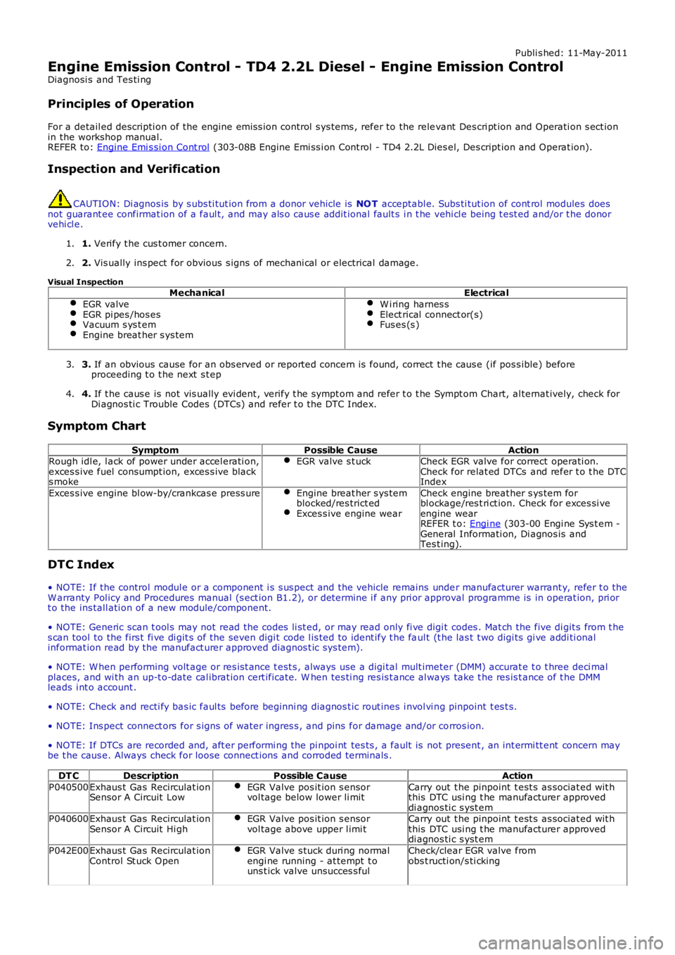
Engine Emission Control - TD4 2.2L Diesel - Engine Emission Control
Diagnosi s and Tes ti ng
Principles of Operation
For a detail ed descripti on of the engine emis s ion control s ys tems , refer to the relevant Des cri pt ion and Operati on s ect ionin the workshop manual.REFER to: Engine Emi s si on Cont rol (303-08B Engine Emi ss i on Cont rol - TD4 2.2L Dies el, Des cript ion and Operat ion).
Inspection and Verification
CAUTION: Di agnos is by s ubs ti tut ion from a donor vehicle is NO T acceptabl e. Subs ti tut ion of cont rol modules doesnot guarant ee confirmat ion of a faul t, and may als o caus e addit ional fault s i n t he vehi cl e being t est ed and/or t he donorvehi cl e.
1. Verify t he cus t omer concern.1.
2. Vis ually ins pect for obvious s igns of mechani cal or electrical damage.2.
Visual InspectionMechanicalElectrical
EGR valveEGR pi pes /hos esVacuum s ys t emEngine breat her s ys tem
W i ring harnes sElect rical connect or(s)Fus es (s )
3. If an obvious cause for an obs erved or report ed concern is found, correct t he caus e (if pos s ible) beforeproceeding t o t he next s t ep3.
4. If t he caus e is not vis ually evi dent , verify t he sympt om and refer t o t he Sympt om Chart, al ternat ively, check forDi agnos ti c Trouble Codes (DTCs) and refer t o t he DTC Index.4.
Symptom Chart
SymptomPossible CauseActionRough idl e, l ack of power under accel erati on,exces s ive fuel consumpt ion, exces s ive blacks moke
EGR valve s t uckCheck EGR valve for correct operati on.Check for relat ed DTCs and refer t o t he DTCIndex
Exces s ive engine bl ow-by/crankcas e press ureEngine breat her s ys temblocked/res trict edExces s ive engine wear
Check engine breat her s ys tem forbl ockage/res t ri ct ion. Check for exces si veengine wearREFER t o: Engi ne (303-00 Engi ne Sys t em -General Informati on, Di agnos is andTes t ing).
DTC Index
• NOTE: If the control modul e or a component i s s us pect and the vehicle remains under manufacturer warrant y, refer t o theW arranty Pol icy and Procedures manual (s ect ion B1.2), or determine i f any pri or approval programme is in operat ion, pri ort o the ins tall ati on of a new module/component.
• NOTE: Generic scan t ool s may not read the codes li st ed, or may read only fi ve digit codes . Mat ch the five di git s from t hes can tool to the firs t fi ve di git s of the seven digi t code l is ted to ident ify t he faul t (t he las t t wo digi ts gi ve addi ti onalinformat ion read by the manufact urer approved diagnos t ic s ys tem).
• NOTE: W hen performing volt age or res is t ance t est s , always use a digi tal mult imeter (DMM) accurat e t o t hree deci malplaces, and wi th an up-t o-date cal ibrat ion cert ificate. W hen tes ti ng res is t ance al ways take t he res is t ance of t he DMMleads i nt o account .
• NOTE: Check and recti fy bas ic faul ts before beginni ng diagnos t ic rout ines i nvol vi ng pinpoint t es t s.
• NOTE: Ins pect connect ors for s igns of water ingres s , and pins for damage and/or corros ion.
• NOTE: If DTCs are recorded and, aft er performi ng the pi npoi nt tes ts , a fault is not present , an int ermi tt ent concern maybe t he caus e. Always check for loose connect ions and corroded terminals .
DT CDescriptionPossible CauseAction
P040500Exhaus t Gas Recirculat ionSensor A Circuit LowEGR Valve pos it ion s ensorvol tage below lower li mitCarry out t he pinpoint t est s as sociat ed wit hthis DTC usi ng t he manufacturer approveddi agnos ti c s yst emP040600Exhaus t Gas Recirculat ionSensor A Circuit Hi ghEGR Valve pos it ion s ensorvol tage above upper l imi tCarry out t he pinpoint t est s as sociat ed wit hthis DTC usi ng t he manufacturer approveddi agnos ti c s yst em
P042E00Exhaus t Gas Recirculat ionControl St uck OpenEGR Valve s tuck duri ng normalengi ne running - at tempt t ouns t ick valve unsucces s ful
Check/clear EGR valve fromobs t ructi on/s ti cking
Page 1160 of 3229
Publi s hed: 11-May-2011
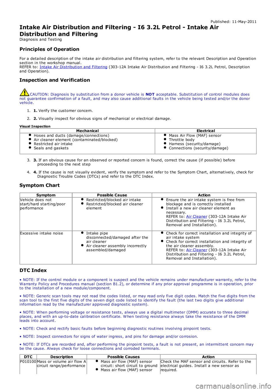
Intake Air Distribution and Filtering - I6 3.2L Petrol - Intake Air
Distribution and Filtering
Diagnosi s and Tes ti ng
Principles of Operation
For a detail ed descripti on of the intake ai r di s tributi on and fi lt eri ng sys t em, refe r t o t he rel evant Des cript ion and Operat ion
s ect ion i n t he works hop manual .
REFER to: Intake Air Di s tributi on and Fil teri ng (303-12A Int ake Air Dis t ri but ion and Fi lt ering - I6 3.2L Petrol, Des cript ion
and Operat ion).
Inspection and Verification CAUTION: Di agnos is by s ubs ti tut ion from a donor vehicle is
NO T acceptabl e. Subs ti tut ion of cont rol modules does
not guarant ee confirmat ion of a faul t, and may als o caus e addit ional fault s i n t he v ehi cl e being t est ed and/or t he donor
vehi cl e.
1. Verify t he cus t omer concern.
1.
2. Vis ually ins pect for obvious s igns of mechani cal or electrical damage.
2.
Visual Inspection Mechanical Electrical
Hos es and duct s (damage/connect ions ) Air cl eaner element (contaminated/bl ocked)
Res tricted ai r int ake
Seals and gas ket s Mass Air Flow (MAF) s ens or
Thrott le body
Harness (s ecurit y/damage)
Connecti ons (s ecurit y/damage)
3.
If an obvious cause for an obs erved or report ed concern is found, correct t he caus e (if pos s ible) before
proceeding t o t he next s t ep
3.
4. If t he caus e is not vis ually evi dent , verify t he sympt om and refer t o t he Sympt om Ch art, al ternat ively, check for
Di agnos ti c Trouble Codes (DTCs) and refer t o t he DTC Index.
4.
Symptom Chart Symptom Possible Cause Action
Vehicle does not
s tart/hard s t art ing/poor
performance Res t ri ct ed/blocked air int ake Res t ri ct ed/blocked air cleaner
el ement Ensure t he air int ake s ys t em i s free from
blockage and i s correct ly i nst all ed Ins t all a new ai r cl eaner element as
neces s ary.
REFER to: Ai r Cl eaner (303-12A Int ake Air
Dis t ri but ion and Fi lt ering - I6 3.2L Petrol,
Removal and Inst all ati on). Exces s ive i nt ake nois e
Int ake pi pe
di s connect ed/damaged aft er the
ai r cl eaner Ai r cleaner as s embly i ncorrect ly
as s embled/damaged Check for correct ins tal lat ion and i nt egri ty of
air i nt ake s ys t em Check for correct ins tal lat ion and i nt egri ty of
t he air cleaner as s embly.
REFER to: Ai r Cl eaner (303-12A Int ake Air
Dis t ri but ion and Fi lt ering - I6 3.2L Petrol,
Removal and Inst all ati on). DTC Index
• NOTE: If the control modul e or a component i s s us pect and the vehicle remains unde r manufacturer warrant y, refer t o the
W arranty Pol icy and Procedures manual (s ect ion B1.2), or determine i f any pri or appr oval programme is in operat ion, pri or
t o the ins tall ati on of a new module/component.
• NOTE: Generic scan t ool s may not read the codes li st ed, or may read only fi ve digi t codes . Mat ch the five di git s from t he
s can tool to the firs t fi ve di git s of the seven digi t code l is ted to ident ify t he fa ul t (t he las t t wo digi ts gi ve addi ti onal
informat ion read by the manufact urer approved diagnos t ic s ys tem).
• NOTE: W hen performing volt age or res is t ance t est s , always use a digi tal mult imeter (DMM) accurat e t o t hree deci mal
places, and wi th an up-t o-date cal ibrat ion cert ificate. W hen tes ti ng res is t ance al wa ys take t he res is t ance of t he DMM
leads i nt o account .
• NOTE: Check and recti fy bas ic faul ts before beginni ng diagnos t ic rout ines i nvol vi n g pinpoint t es t s.
• NOTE: Ins pect connect ors for s igns of water ingres s , and pins for damage and/or co rros ion.
• NOTE: If DTCs are recorded and, aft er performi ng the pi npoi nt tes ts , a fault is no t present , an int ermi tt ent concern may
be t he caus e. Always check for loose connect ions and corroded terminals .
DT C Description Possible Causes Action
P010100 Mas s or volume ai r fl ow A
circui t range/performance Mas s ai r fl ow (MAF) s ens or
ci rcuit : short ci rcuit t o ground Mas s ai r fl ow (MAF) s ens or Check t he MAF s ensor and circui ts . Refer t o t he
electrical gui des . Ins t all a new s ens or as
required.
Page 1172 of 3229
Publi s hed: 11-May-2011
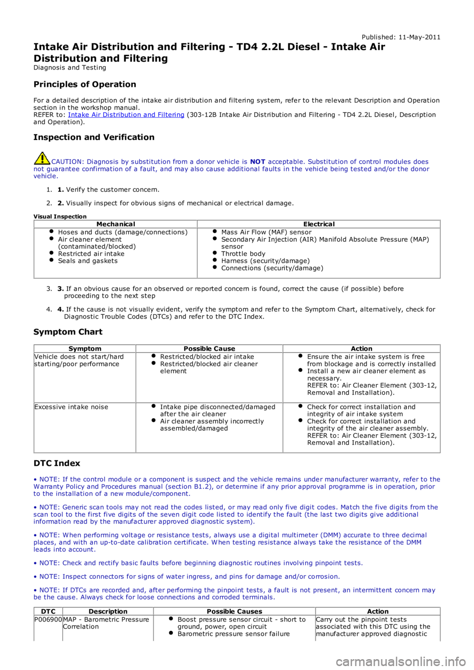
Intake Air Distribution and Filtering - TD4 2.2L Diesel - Intake Air
Distribution and Filtering
Diagnosi s and Tes ti ng
Principles of Operation
For a detail ed descripti on of the intake ai r di s tributi on and fi lt eri ng sys t em, refer t o t he rel evant Des cript ion and Operat ions ect ion i n t he works hop manual .REFER to: Intake Air Di s tributi on and Fil teri ng (303-12B Int ake Air Dis t ri but ion and Fi lt ering - TD4 2.2L Di esel , Des cri pti onand Operat ion).
Inspection and Verification
CAUTION: Di agnos is by s ubs ti tut ion from a donor vehicle is NO T acceptabl e. Subs ti tut ion of cont rol modules doesnot guarant ee confirmat ion of a faul t, and may als o caus e addit ional fault s i n t he vehi cl e being t est ed and/or t he donorvehi cl e.
1. Verify t he cus t omer concern.1.
2. Vis ually ins pect for obvious s igns of mechani cal or electrical damage.2.
Visual InspectionMechanicalElectrical
Hos es and duct s (damage/connect ions )Air cl eaner element(cont aminated/bl ocked)Res tricted ai r int akeSeals and gas ket s
Mas s Ai r Fl ow (MAF) sens orSecondary Air Injecti on (AIR) Manifol d Abs ol ute Pres sure (MAP)s ens orThrot t le bodyHarnes s (s ecurit y/damage)Connect ions (s ecuri ty/damage)
3. If an obvious cause for an obs erved or report ed concern is found, correct t he caus e (if pos s ible) beforeproceeding t o t he next s t ep3.
4. If t he caus e is not vis ually evi dent , verify t he sympt om and refer t o t he Sympt om Chart, al ternat ively, check forDi agnos ti c Trouble Codes (DTCs) and refer t o t he DTC Index.4.
Symptom Chart
SymptomPossible CauseAction
Vehicle does not s tart/hards tarti ng/poor performanceRes t rict ed/blocked ai r int akeRes t rict ed/blocked ai r cleanerel ement
Ens ure the ai r int ake sys tem is freefrom bl ockage and is correctl y ins tal ledIns t al l a new ai r cl eaner element asneces sary.REFER to: Air Cl eaner Element (303-12,Removal and Inst all at ion).
Exces s ive i nt ake nois eIntake pi pe dis connect ed/damagedafter t he air cleanerAi r cl eaner as s embl y i ncorrect lyas s embled/damaged
Check for correct ins tal lati on andint egrit y of air i nt ake s ys t emCheck for correct ins tal lati on andint egrit y of the ai r cleaner as s embly.REFER to: Air Cl eaner Element (303-12,Removal and Inst all at ion).
DTC Index
• NOTE: If the control modul e or a component i s s us pect and the vehicle remains under manufacturer warrant y, refer t o theW arranty Pol icy and Procedures manual (s ect ion B1.2), or determine i f any pri or approval programme is in operat ion, pri ort o the ins tall ati on of a new module/component.
• NOTE: Generic scan t ool s may not read the codes li st ed, or may read only fi ve digit codes . Mat ch the five di git s from t hes can tool to the firs t fi ve di git s of the seven digi t code l is ted to ident ify t he faul t (t he las t t wo digi ts gi ve addi ti onalinformat ion read by the manufact urer approved diagnos t ic s ys tem).
• NOTE: W hen performing volt age or res is t ance t est s , always use a digi tal mult imeter (DMM) accurat e t o t hree deci malplaces, and wi th an up-t o-date cal ibrat ion cert ificate. W hen tes ti ng res is t ance al ways take t he res is t ance of t he DMMleads i nt o account .
• NOTE: Check and recti fy bas ic faul ts before beginni ng diagnos t ic rout ines i nvol vi ng pinpoint t es t s.
• NOTE: Ins pect connect ors for s igns of water ingres s , and pins for damage and/or corros ion.
• NOTE: If DTCs are recorded and, aft er performi ng the pi npoi nt tes ts , a fault is not present , an int ermi tt ent concern maybe t he caus e. Always check for loose connect ions and corroded terminals .
DT CDescriptionPossible CausesAction
P006900MAP - Barometric Press ureCorrelat ionBoos t pres s ure s ensor circui t - s hort toground, power, open circui tBarometric pres s ure sens or fail ure
Carry out t he pinpoint t est sass ociated wit h t hi s DTC us ing t hemanufact urer approved diagnost ic
Page 1198 of 3229
4-Fuel Pump Dri ver Module (FPDM)
5-Ambi ent ai r temperat ure sens or
6-Bat tery Juncti on Box (BJB)7-Bat tery
OVERVIEW
The Engi ne Control Module (ECM) controls t he fol lowing:
Engi ne fuel ingIgni ti on ti mingClos ed loop fuelingKnock controlIdl e s peed cont rolEmis s ion controlOn Board Diagnost icsSpeed cont rol.
The ECM controls engine fuel ing by provi ding s equent ial fuel inject ion t o al l cyli nders . Ignit ion i s cont rol led by a directignit ion sys tem, provi ded by 6 pl ug top coil s . The ECM is abl e t o detect and correct for i gni ti on knock on each cyl inder andadjus t the ignit ion t imi ng for each cyl inder to achieve opt imum performance.
The ECM us es a t orque-bas ed s trategy t o generate the t orque requi red by t he dri ver and ot her vehicle cont rol modules .The ECM us es various s ens ors t o determine t he t orque requi red from the engine. The ECM al so int erfaces wi th ot hervehi cl e elect ronic control modul es vi a t he high s peed Control ler Area Network (CAN) bus , to obt ain addit ional informat ion(for exampl e road speed from the Ant i-lock Brake Sys tem (ABS) module). The ECM proces ses t hese si gnal s and deci deshow much t orque t o generate. Torque i s t hen generat ed by us ing vari ous act uat ors to supply ai r, fuel and s park t o t heengi ne.
The ECM al so us es an el ect ronic throt tl e s yst em which compris es t he electric t hrot tle as sembl y and an Accel erator PedalPosi ti on (APP) s ensor.
The ECM al so interfaces wit h t he immobili zat ion sys tem t o help prevent t he vehi cl e being s t art ed wit hout properauthori zat ion.For addit ional informat ion, refer t o: Anti -Theft - Act ive (419-01, Des cri pt ion and Operati on).
CONTROL DIAGRAM SHEET 1 OF 2
• NOTE: A = Hardwi red; N = Medium s peed CAN bus; O = Local Int erconnect Network (LIN) bus
Page 1202 of 3229
12-Res trai nts Cont rol Module (RCM)
13-Knock sens ors (2 off)
14-Fuel rail t emperature/pres s ure s ens or15-Clockspring
16-Terrain respons e cont rol module
17-Trans mis s ion Cont rol Module (TCM)18-ABS module
19-Diagnos ti c socket
20-CJB
ENGINE CONTROL MODULE (ECM)
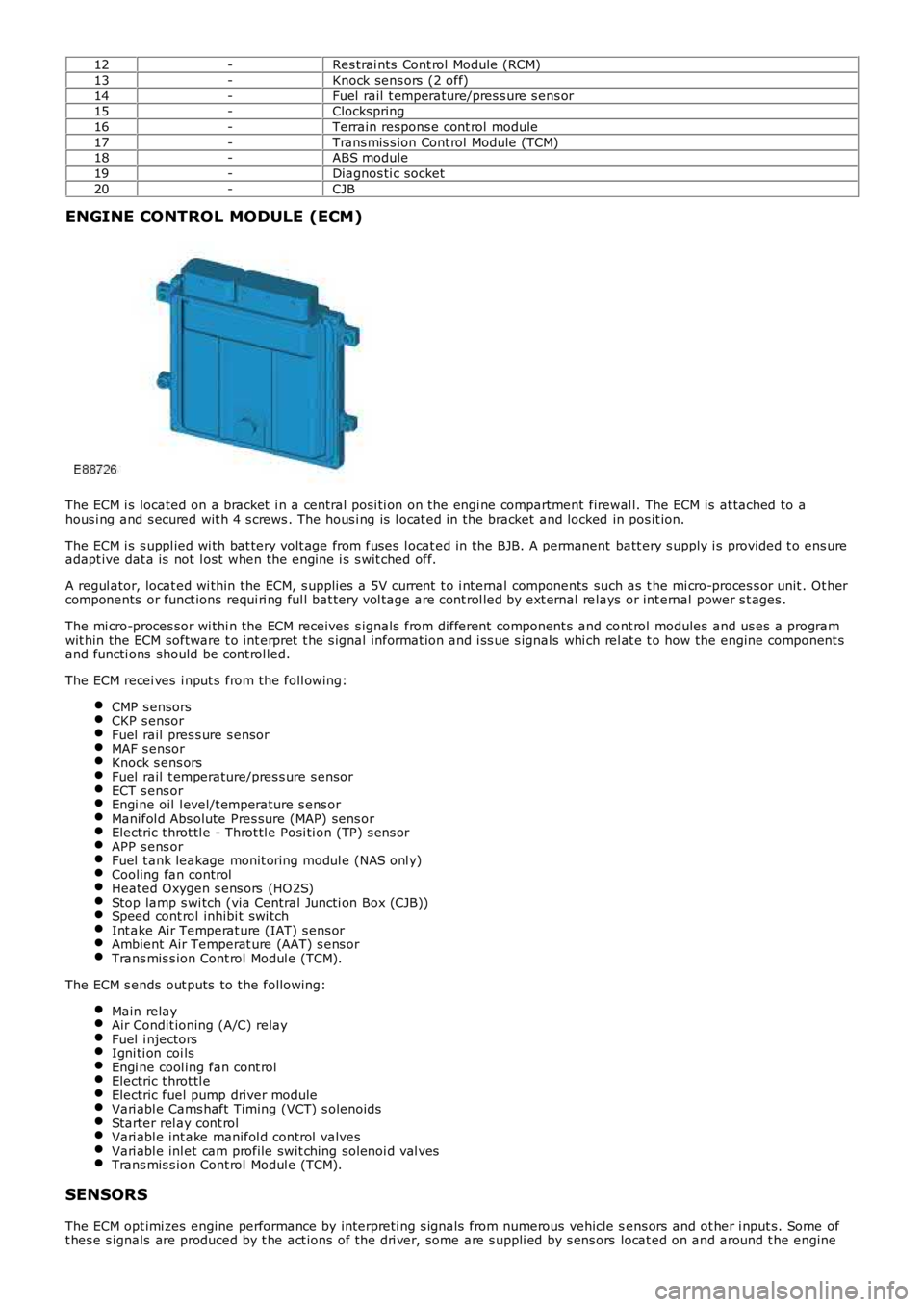
The ECM i s located on a bracket i n a central pos i ti on on the engi ne compartment firewal l. The ECM is at tached to ahous i ng and s ecured wit h 4 s crews . The hous i ng is l ocat ed in the bracket and locked in pos it ion.
The ECM i s s uppl ied wi th bat tery volt age from fuses l ocat ed in the BJB. A permanent batt ery s upply i s provided t o ens ureadapt ive dat a is not l ost when the engine i s s wit ched off.
A regul ator, locat ed wi thin the ECM, s upplies a 5V current t o i nt ernal components such as t he mi cro-proces s or unit . Ot hercomponents or funct ions requi ri ng ful l bat tery vol tage are cont rol led by ext ernal relays or int ernal power s t ages .
The mi cro-proces sor wi thi n the ECM receives s ignals from different component s and cont rol modules and us es a programwit hin the ECM software t o int erpret t he s ignal informat ion and i ss ue s ignals whi ch rel at e t o how the engine component sand functi ons should be cont rol led.
The ECM recei ves i nput s from the foll owing:
CMP s ensorsCKP s ensorFuel rail pres s ure s ensorMAF s ensorKnock s ens orsFuel rail t emperature/pres s ure s ensorECT s ens orEngi ne oil l evel/t emperature s ens orManifol d Abs olute Pres sure (MAP) sens orElectric t hrot tl e - Throt tl e Posi ti on (TP) s ens orAPP s ens orFuel t ank leakage monit oring modul e (NAS onl y)Cooling fan controlHeated Oxygen s ens ors (HO2S)Stop lamp s wi tch (via Central Juncti on Box (CJB))Speed cont rol inhibi t swi tchInt ake Air Temperat ure (IAT) s ens orAmbient Air Temperat ure (AAT) s ens orTrans mis s ion Cont rol Modul e (TCM).
The ECM s ends out puts to t he followi ng:
Main relayAir Condit ioning (A/C) relayFuel i njectorsIgni ti on coi lsEngi ne cool ing fan cont rolElectric t hrot tl eElectric fuel pump driver moduleVari abl e Cams haft Timing (VCT) s olenoidsStarter rel ay cont rolVari abl e int ake manifol d control valvesVari abl e inl et cam profile swit ching sol enoi d val vesTrans mis s ion Cont rol Modul e (TCM).
SENSORS
The ECM opt imi zes engine performance by interpreti ng s ignals from numerous vehicle sens ors and ot her i nput s. Some oft hes e s ignals are produced by t he act ions of t he dri ver, some are s uppli ed by s ens ors locat ed on and around t he engine
Page 1205 of 3229
t he ignit ion t imingt he engi ne load.
The ECM moni tors the MAF s ens or for faul ts and can s t ore fault rel ated codes. Thes e can be ret ri eved us ing a Land Roverapproved diagnos t ic s yst em.
Int ake Air Temperat ure (IAT) Sens or
The IAT s ens or measures the temperat ure of t he i nt ake air entering t he engine. The sens or is a temperat ure dependantres is t or (t hermi st or). The thermis t or i s a NTC sens or element. The el ement resi s tance decreas es as t he s ens ort emperature increas es. The ECM suppli es the sens or wit h a 5V reference volt age and a ground and meas ures the returneds ignal as a t emperature.
The res is t ance i n t he s ens or changes wi th i ntake air t emperat ure. A l ow i nt ake air temperature wi ll res ult i n a hi gh vol tagebeing returned t o t he ECM and hi gh int ake ai r temperature wil l ret urn a low volt age reading of bet ween 0 - 5V.
The ECM moni tors the IAT s ens or for fault s and can s tore faul t relat ed codes . Thes e can be retrieved us ing a Land Roverapproved diagnos t ic s yst em. If the IAT s ensor fails , t he ECM us es a defaul t temperature val ue usi ng the fuel railpres s ure/t emperat ure s ensor.
Knock Sensors
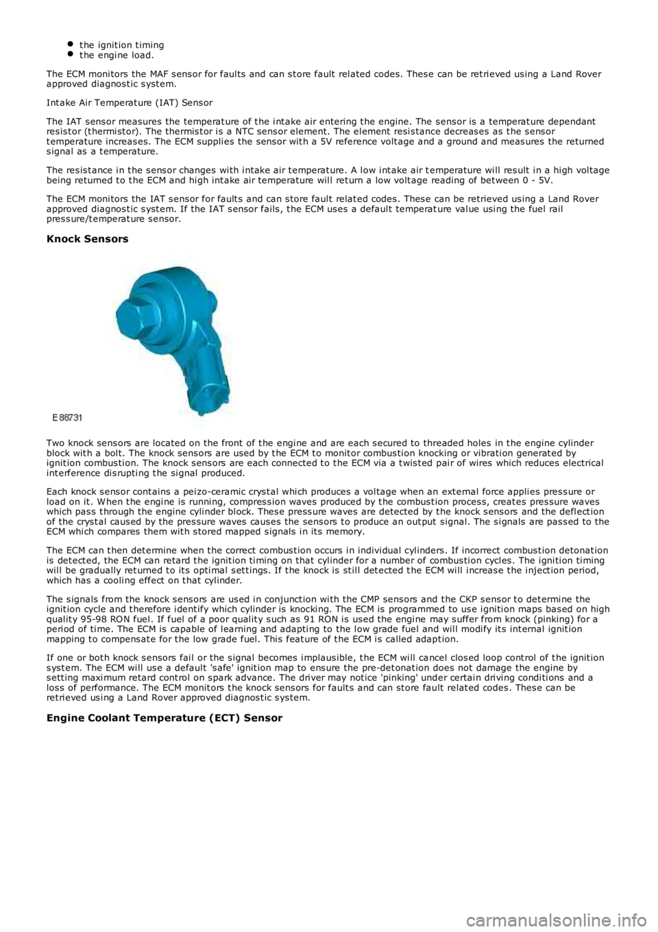
Two knock sens ors are located on the front of t he engi ne and are each s ecured to threaded holes in t he engine cylinderblock wit h a bol t. The knock sens ors are us ed by t he ECM t o monit or combus ti on knocking or vibrati on generat ed byignit ion combus ti on. The knock s ens ors are each connected t o t he ECM via a t wis t ed pai r of wires which reduces electricalint erference di s rupti ng t he si gnal produced.
Each knock s ens or cont ains a pei zo-ceramic crys t al whi ch produces a vol tage when an ext ernal force appli es pres s ure orload on it . W hen t he engi ne is runni ng, compres s ion waves produced by t he combus t ion proces s, creat es pres sure waveswhich pas s t hrough the engine cyli nder bl ock. Thes e press ure waves are detected by the knock s ens ors and the defl ect ionof the crys t al caus ed by the pres sure waves caus es the sens ors t o produce an out put s ignal. The s i gnals are pas s ed to theECM whi ch compares them wit h s tored mapped s ignal s i n it s memory.
The ECM can t hen det ermine when t he correct combus t ion occurs i n indivi dual cyl inders . If incorrect combus t ion detonat ionis det ect ed, the ECM can retard t he ignit ion ti ming on that cyl inder for a number of combus ti on cycl es . The i gni ti on ti mingwil l be gradually ret urned t o it s opti mal s et t ings. If t he knock is st il l det ected the ECM wi ll i ncreas e t he i nject ion period,which has a cooli ng effect on t hat cyl inder.
The s ignals from the knock s ens ors are us ed i n conjunct ion wi th the CMP sens ors and t he CKP s ens or t o det ermi ne theignit ion cycle and t herefore i dent ify which cylinder is knocki ng. The ECM is programmed to us e i gni ti on maps bas ed on highqual it y 95-98 RO N fuel . If fuel of a poor qual it y s uch as 91 RON i s us ed the engi ne may s uffer from knock (pinking) for aperi od of ti me. The ECM is capable of l earning and adapti ng to the l ow grade fuel and wil l modi fy it s int ernal ignit ionmapping t o compens at e for t he low grade fuel . Thi s feat ure of t he ECM i s called adapt ion.
If one or bot h knock s ensors fai l or the s ignal becomes i mplaus ible, t he ECM wi ll cancel clos ed loop cont rol of t he ignit ions ys t em. The ECM wi ll us e a defaul t 's afe' ignit ion map to ens ure the pre-det onat ion does not damage the engine bys ett ing maxi mum retard cont rol on s park advance. The dri ver may not ice 'pinking' under certai n dri vi ng condi ti ons and alos s of performance. The ECM monit ors t he knock s ens ors for fault s and can st ore fault relat ed codes . Thes e can beret ri eved us i ng a Land Rover approved diagnos t ic s ys tem.
Engine Coolant Temperature (ECT) Sensor
Page 1212 of 3229
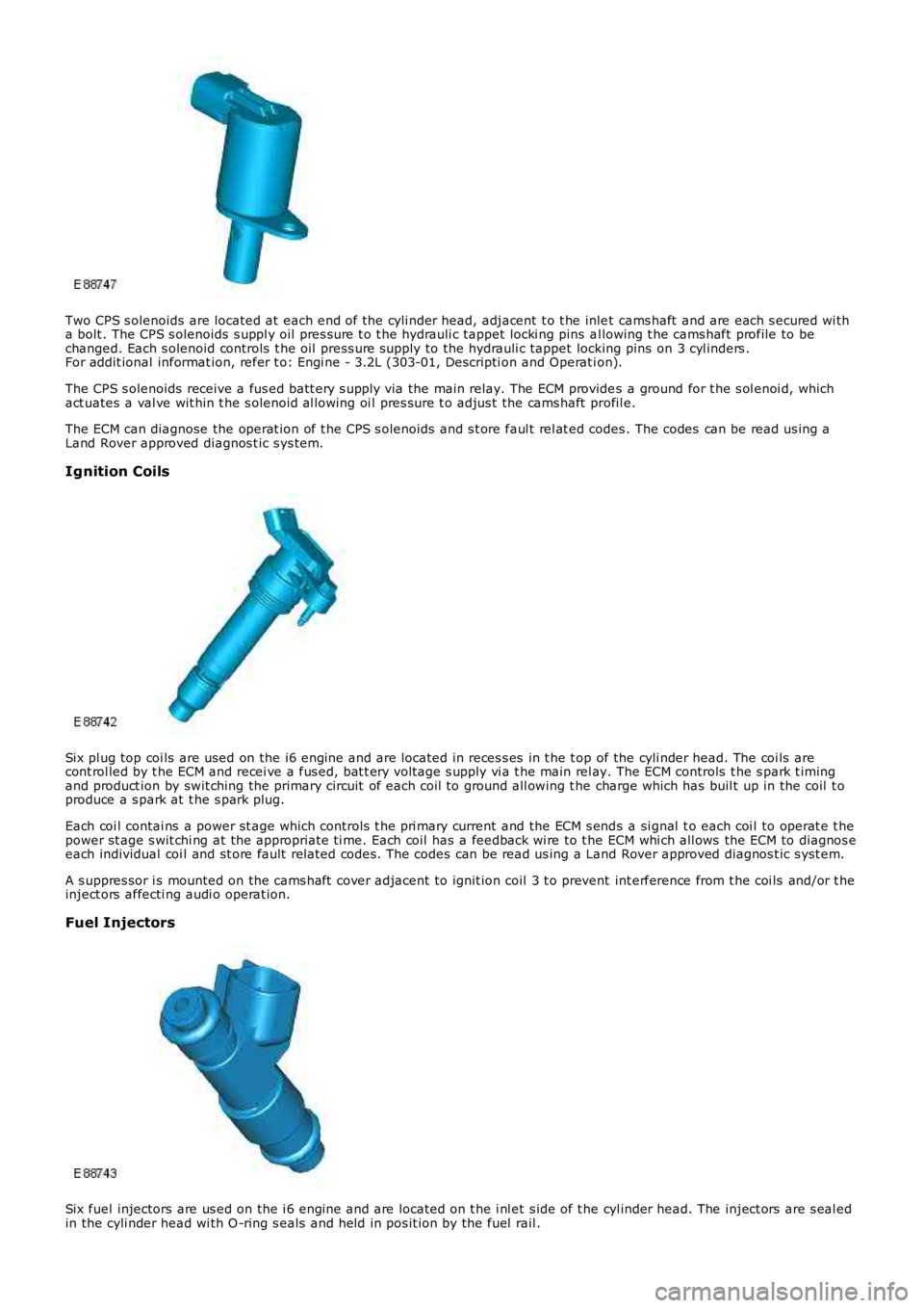
Two CPS s olenoids are located at each end of the cyli nder head, adjacent t o t he inlet cams haft and are each s ecured wi tha bolt . The CPS s olenoids s uppl y oil pres s ure t o t he hydrauli c tappet locki ng pins al lowing t he cams haft profile to bechanged. Each s olenoid controls t he oil press ure supply to the hydrauli c tappet locking pins on 3 cyl inders .For addit ional informat ion, refer t o: Engi ne - 3.2L (303-01, Descripti on and Operat ion).
The CPS s olenoids receive a fus ed batt ery s upply via the main relay. The ECM provides a ground for t he s ol enoi d, whichact uates a val ve wit hin t he s olenoid al lowing oi l pres sure t o adjus t the cams haft profil e.
The ECM can diagnose the operat ion of t he CPS s olenoids and s t ore faul t rel at ed codes . The codes can be read us ing aLand Rover approved diagnos t ic s ys tem.
Ignition Coils
Six pl ug top coi ls are used on the i6 engine and are located in reces s es in t he t op of the cyli nder head. The coi ls arecont rol led by t he ECM and recei ve a fus ed, bat t ery volt age s upply vi a t he main rel ay. The ECM controls t he s park t imingand product ion by swit ching the primary circuit of each coil to ground all owing t he charge which has buil t up in the coil t oproduce a s park at t he s park plug.
Each coi l contai ns a power st age which controls t he pri mary current and the ECM s ends a si gnal t o each coi l to operat e t hepower st age s wit chi ng at the appropriate ti me. Each coil has a feedback wi re to t he ECM whi ch all ows the ECM to diagnos eeach individual coi l and st ore fault related codes. The codes can be read us ing a Land Rover approved diagnos t ic s yst em.
A s uppres sor i s mounted on the cams haft cover adjacent to ignit ion coil 3 t o prevent int erference from t he coi ls and/or t heinject ors affecti ng audi o operat ion.
Fuel Injectors
Six fuel injectors are us ed on the i 6 engine and are located on t he i nl et s ide of t he cyl inder head. The inject ors are s eal edin the cyli nder head wi th O -ring s eals and held in pos it ion by the fuel rail .