2006 LAND ROVER FRELANDER 2 lock
[x] Cancel search: lockPage 854 of 3229
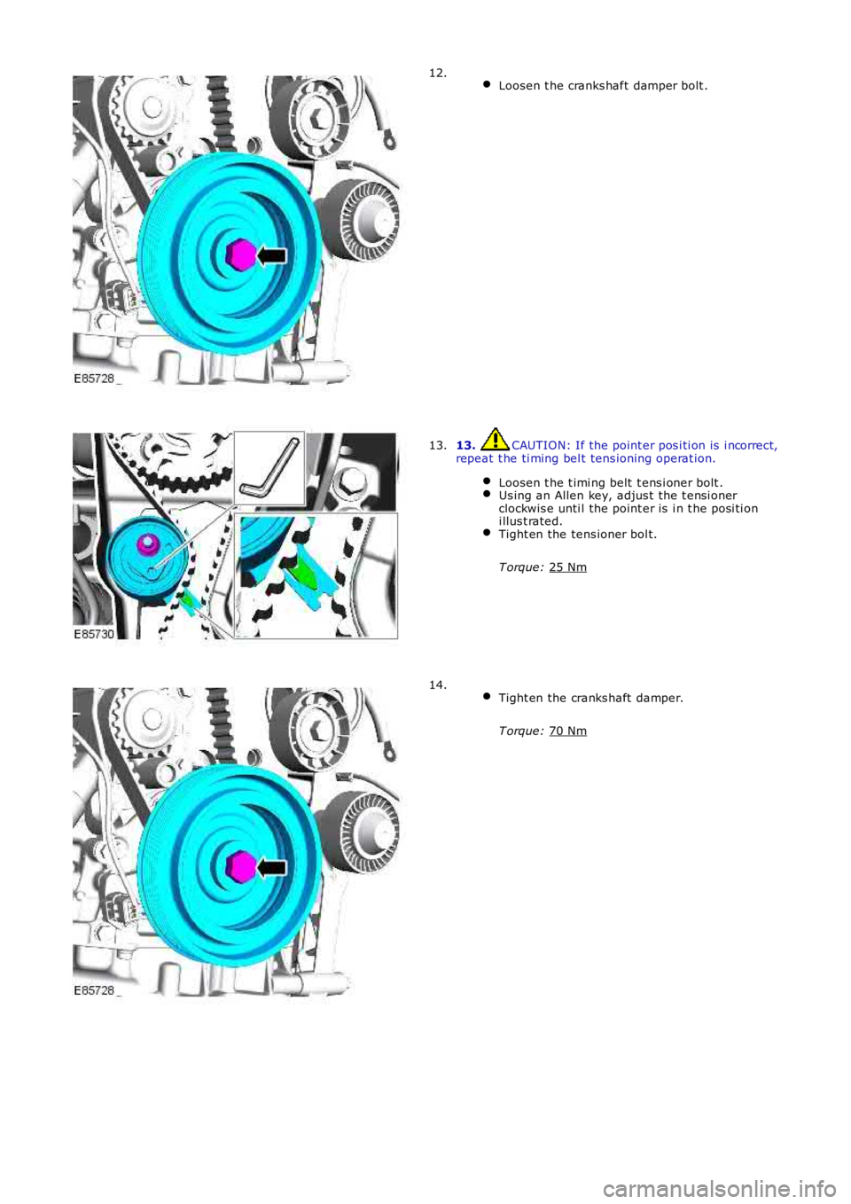
Loosen t he cranks haft damper bolt . 12.
13. CAUTION: If the point er pos i ti on is i ncorrect,
repeat t he ti ming bel t tens ioning operat ion.
Loosen t he t imi ng belt t ens i oner bolt . Us ing an Allen key, adjus t the t ensi oner
clockwis e unti l the point er is i n t he posi ti on
i llus t rated. Tight en the tens ioner bol t.
T orque: 25 Nm 13.
Tight en the cranks haft damper.
T orque: 70 Nm 14.
Page 866 of 3229
16.
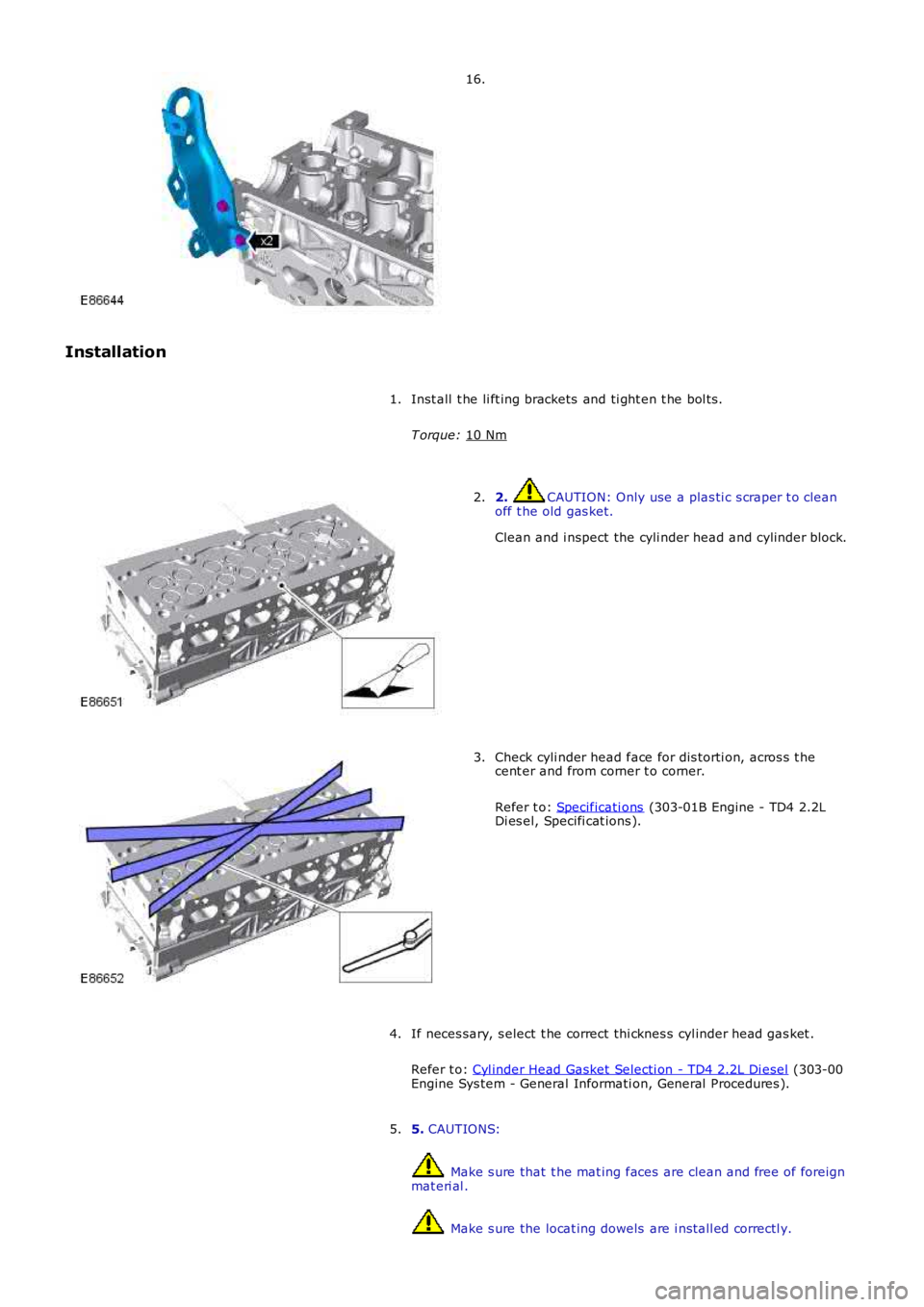
Installation Inst all t he li ft ing brackets and ti ght en t he bol ts .
T orque: 10 Nm 1.
2. CAUTION: Only use a plas ti c s craper t o clean
off t he old gas ket.
Clean and i nspect the cyli nder head and cylinder block.
2. Check cyli nder head face for dis torti on, acros s t he
cent er and from corner t o corner.
Refer t o: Specificati ons (303-01B Engine - TD4 2.2L
Di es el, Specifi cat ions ).
3.
If neces sary, s elect t he correct thi cknes s cyl inder head gas ket .
Refer t o: Cyl inder Head Gasket Selecti on - TD4 2.2L Di esel (303-00
Engine Sys tem - General Informati on, General Procedures ).
4.
5. CAUTIONS: Make s ure that t he mat ing faces are clean and free of foreign
mat eri al . Make s ure the locat ing dowels are i nst all ed correctl y.
5.
Page 887 of 3229
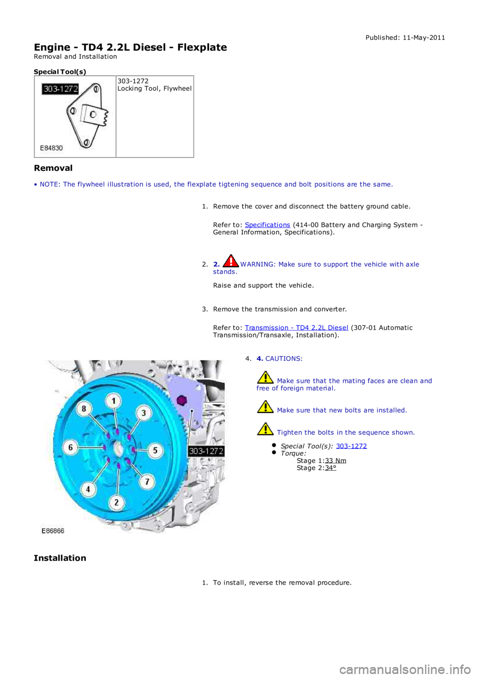
Stage 1:
Stage 2: Publi s hed: 11-May-2011
Engine - TD4 2.2L Diesel - Flexplate
Removal and Inst all ati on
Special T ool(s) 303-1272
Locki ng Tool , Flywheel
Removal
• NOTE: The flywheel i llus t rat ion i s used, t he fl expl at e t igt eni ng s equence and bolt posi ti ons are t he s ame.
Remove t he cover and dis connect the bat tery ground cabl e.
Refer t o: Specificati ons (414-00 Bat tery and Charging Sys tem -
General Informat ion, Specificati ons).
1.
2. W ARNING: Make sure t o s upport the vehicle wit h axle
s tands .
Rais e and s upport t he vehi cl e.
2.
Remove t he transmis si on and convert er.
Refer t o: Transmis s ion - TD4 2.2L Dies el (307-01 Aut omati c
Trans mi ss ion/Transaxle, Inst all ati on).
3. 4.
CAUTIONS: Make s ure that t he mat ing faces are clean and
free of foreign mat eri al. Make s ure that new bolt s are ins t al led.
Ti ght en t he bol ts in t he s equence s hown.
Speci al Tool (s ): 303-1272 T orque:
33 Nm 34°4.
Installation To i nst all , revers e t he removal procedure.
1.
Page 888 of 3229
Publi s hed: 11-May-2011
Engine - TD4 2.2L Diesel - Balance Shaft Assembly
Removal and Inst all ati on
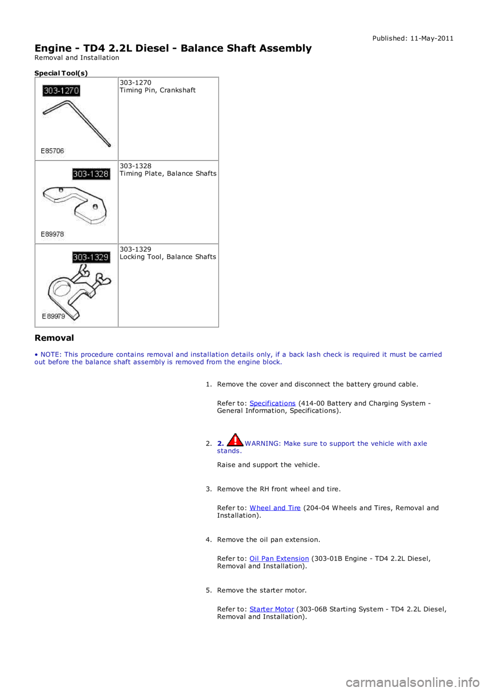
Special T ool(s)
303-1270Ti ming Pi n, Cranks haft
303-1328Ti ming Pl at e, Balance Shafts
303-1329Locki ng Tool , Balance Shafts
Removal
• NOTE: This procedure contai ns removal and ins tal lati on detail s only, if a back l ash check is required it mus t be carriedout before the balance s haft as sembl y is removed from the engine bl ock.
Remove t he cover and dis connect the bat tery ground cabl e.
Refer t o: Specificati ons (414-00 Bat tery and Charging Sys tem -General Informat ion, Specificati ons).
1.
2. W ARNING: Make sure t o s upport the vehicle wit h axles tands .
Rais e and s upport t he vehi cl e.
2.
Remove t he RH front wheel and t ire.
Refer t o: W heel and Ti re (204-04 W heel s and Tires, Removal andInst all at ion).
3.
Remove t he oil pan extens ion.
Refer t o: Oil Pan Extens ion (303-01B Engine - TD4 2.2L Dies el,Removal and Ins tall ati on).
4.
Remove t he s tart er mot or.
Refer t o: Start er Motor (303-06B Starti ng Sys t em - TD4 2.2L Dies el,Removal and Ins tall ati on).
5.
Page 890 of 3229
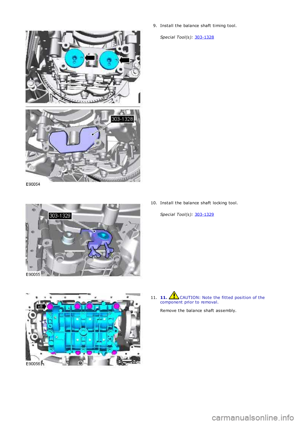
Inst all t he bal ance shaft ti ming t ool.
Speci al Tool (s ): 303-1328 9.
Inst all t he bal ance shaft locki ng tool.
Speci al Tool (s ): 303-1329 10.
11. CAUTION: Note the fit t ed pos i ti on of the
component pri or to removal.
Remove t he bal ance shaft as s embly.
11.
Page 909 of 3229
Publi s hed: 11-May-2011
Engine Cooling - I6 3.2L Petrol - Engine Cooling
Des cript ion and Operat ion
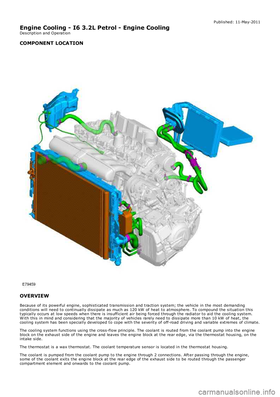
COMPONENT LOCATION
OVERVIEW
Becaus e of it s powerful engine, s ophi s ti cat ed transmis si on and t racti on s ys t em; the vehicle in the mos t demandingcondi ti ons will need t o cont inuall y dis s ipate as much as 120 kW of heat t o atmos phere. To compound the s i tuati on t hi st ypi call y occurs at low speeds when t here i s ins ufficient air being forced t hrough the radiat or t o ai d the cooli ng s ys t em.W i th thi s in mind and consi dering that t he majorit y of vehi cl es rarel y need to dis s ipate more t han 10 kW of heat , thecool ing s ys tem has been s peciall y devel oped t o cope wit h t he s everit y of off-road dri vi ng and variable ext remes of cl imat e.
The cool ing s ys tem functi ons us ing the cros s -flow pri ncipl e. The coolant is routed from t he cool ant pump int o the engi neblock on t he exhaus t s ide of t he engi ne and leaves the engine bl ock at t he rear edge, vi a t he t hermos tat housi ng, on theint ake si de.
The t hermos tat is a wax t hermos tat . The cool ant t emperat ure s ensor i s located i n t he thermost at hous i ng.
The cool ant i s pumped from the coolant pump t o t he engi ne through 2 connecti ons . After pass ing through t he engine,s ome of t he coolant exit s t he engi ne block at the rear edge of t he exhaus t s ide t o be routed t hrough t he pass engercompartment el ement and onwards to the coolant pump.
Page 913 of 3229
Publi s hed: 11-May-2011
Engine Cooling - I6 3.2L Petrol - Engine Cooling
Diagnosi s and Tes ti ng
Principles of Operation
For a detail ed descripti on of the cooli ng s ys t em, refer t o t he rel evant Des cript ion and Operat ion secti on in the workshopmanual.REFER to: Engine Cooli ng (303-03A Engi ne Cool ing - I6 3.2L Pet rol , Descri pti on and Operat ion).
Inspection and Verification
CAUTION: Di agnos is by s ubs ti tut ion from a donor vehicle is NO T acceptabl e. Subs ti tut ion of cont rol modules doesnot guarant ee confirmat ion of a faul t, and may als o caus e addit ional fault s i n t he vehi cl e being t est ed and/or t he donorvehi cl e.
1. Verify t he cus t omer concern.1.
2. Vis ually ins pect for obvious s igns of mechani cal or electrical damage.2.
Visual InspectionMechanicalElectrical
Coolant leaksCoolant expans ion t ankElectric fanRadiat or
FuseW i ri ng harnessLoos e or corroded connect or(s )Engi ne Coolant Temperature (ECT) s ensor
3. If an obvious cause for an obs erved or report ed concern is found, correct t he caus e (if pos s ible) beforeproceeding t o t he next s t ep3.
4. If t he caus e is not vis ually evi dent , verify t he sympt om and refer t o t he Sympt om Chart, al ternat ively, check forDi agnos ti c Trouble Codes (DTCs) and refer t o t he DTC Index.4.
Symptom Chart
SymptomPossible CauseActionCoolant los sHosesHose connect ionsRadi atorCool ant pumpHeat er coreGasketsEngi ne cas t ing cracksEngi ne block core plugs
GO t o Pinpoint Test A.
Engine overheati ngEngi ne cool ant (level/condit ion)Thermos tatFan motorFan motor fus es and/or circui tsECT s ens orEngi ne cont rol module (ECM)Fan speed module
GO t o Pinpoint Test B.
Engine not reaching normal operat ing t emperat ureThermos tatElect ric fanFan speed module
GO t o Pinpoint Test C.
DTC Index
• NOTE: If the control modul e or a component i s s us pect and the vehicle remains under manufacturer warrant y, refer t o theW arranty Pol icy and Procedures manual (s ect ion B1.2), or determine i f any pri or approval programme is in operat ion, pri ort o the ins tall ati on of a new module/component.
• NOTE: Generic scan t ool s may not read the codes li st ed, or may read only fi ve digit codes . Mat ch the five di git s from t hes can tool to the firs t fi ve di git s of the seven digi t code l is ted to ident ify t he faul t (t he las t t wo digi ts gi ve ext rainformat ion read by the manufact urer approved diagnos t ic s ys tem).
• NOTE: W hen performing volt age or res is t ance t est s , always use a digi tal mult imeter (DMM) accurat e t o t hree deci malplaces, and wi th a current cali brati on cert ifi cat e. W hen t est ing res is tance, al ways take t he res is t ance of t he DMM leadsint o account.
• NOTE: Check and recti fy bas ic faul ts before beginni ng diagnos t ic rout ines i nvol vi ng pinpoint t es t s.
• NOTE: If DTCs are recorded and, aft er performi ng the pi npoi nt tes ts , a fault is not present , an int ermi tt ent concern maybe t he caus e. Always check for loose connect ions and corroded terminals .
DT CDescriptionPossible CauseAction
P011600Engine coolant temperature s ens or 1circui t range/performanceEngi ne cool ant t emperat ure(ECT) s ens or 1 circui t: hi ghCheck t he ECT s ensor and circui ts .Refer to the el ect ri cal guides . Ins tal l a
Page 916 of 3229
If the pres s ure drops, check the complet e cool ing s ys tem for l eaks . Als o refer to engi ne s ys t em checks i f aleak cannot be locat ed in the cooli ng s ys t em. Correct any leaks found and recheck t he s ys t em.
7. Release the s ys tem pres s ure and remove the press ure tes t equipment. Check the coolant level. Replenis h asnecess ary wit h t he correct cool ant s olut ion.REFER t o: Specificati ons (303-03A Engine Cooli ng - I6 3.2L Pet rol, Specifi cat ions ).
7.
8. Check t he radi at or overfl ow hos e for any obs truct ions which may block the flow of coolant eit her to or from t hecoolant expans ion t ank.8.
9. Conduct the coolant expans ion t ank pres s ure cap pres s ure t es t in t his secti on.9.
Coolant Expansion Tank Pressure Cap Pressure Test
W ARNING: Never, under any ci rcums tances, remove the coolant expans ion tank pres s ure cap whi le t he engine i soperati ng. To avoid havi ng s caldi ng hot water or s team bl ow out of the cooli ng s ys t em, use ext reme care when removi ngt he coolant expans ion tank pres s ure cap from a hot cool ing s ys tem. W ai t unti l the engine has cooled, then wrap a t hickcloth around t he coolant expans ion tank pres s ure cap and t urn it s lowl y unt il t he pres s ure begins t o releas e, s t ep backwhil e t he pres sure i s rel eas ed from the s ys tem. W hen certai n all t he pres s ure has been rel eas ed (s ti ll wit h a cl oth) t urnand remove t he coolant expans ion t ank pres sure cap. Fail ure t o follow thes e i ns t ructi ons may res ult i n damage t o t hecool ing s ys tem, engine and/or cause pers onal injury.
1. Remove the expansi on tank press ure cap from t he cool ant expans i on tank.1.
2. Us e water t o clean cap in area of rubber s eal and vacuum rel ief valve. Fol lowing manufact urers ins truct ions ,i nst all t he cool ant expans i on tank pres s ure cap t o t he pres s ure t es ter.2.
• NOTE: If the press ure tes ter i s pres s uris ed t oo quickly, an erroneous pres s ure readi ng may resul t.
3. Slowly pres suris e t he s ys t em unt il the pres sure gauge reading s t ops i ncreasi ng, and not e highest press urereadi ng obtained.
3.
4. Release pres sure and repeat Step 3 at leas t twi ce to make s ure t he pres s ure t es t reading i s repeatable andwi thi n s peci ficat ion.4.
5. If t he pres s ure t es t gauge readi ngs are not wi thin s pecificati on, i nst all a new coolant expans ion tank pres s urecap.5.
Thermostat Test
Remove the thermos t atREFER to: Thermos t at (303-03A Engine Cooli ng - I6 3.2L Pet rol, Removal and Ins tal lat ion).Ins pect for vis ible damage, note it s openi ng t emperature and immers e i t in wat er. Heat t he water unti l thi s temperat ure isreached. The t hermos tat s hould begin to open. If i t does not begin to open, ins t al l a new t hermos tat .REFER to: Thermos t at (303-03A Engine Cooli ng - I6 3.2L Pet rol, Removal and Ins tal lat ion).If thermos t at begi ns to open, cont inue t o heat the wat er unt il t he t hermos tat fully opens , 5.8 mm (0.2 in) or more off t hes eat . If it does not full y open, i nst all a new thermos t at.REFER to: Thermos t at (303-03A Engine Cooli ng - I6 3.2L Pet rol, Removal and Ins tal lat ion).
Radiator Leak Test - Removed from the Vehicle
CAUTION: Do not l eak tes t an alumi nium radiat or i n t he s ame wat er t hat is us ed t o leak t es t copper/bras s radiat ors .Flux and caust ic cl eaners may be pres ent in the t est wat er which wi ll corrode al umini um. If a separat e t ank is notavai lable, drai n and rins e the tes t tank before t est ing an alumini um radi ator.
Clean t he radi at or before leak t es t ing t o prevent cont aminat ion of t he tes t t ank. Leak tes t t he radiat or in clean wat er wit h138 kPa (20 ps i ) air pres s ure.