Page 684 of 3229

Installation
Inst all t he dowel s .
1.
Clean and i nspect the cyli nder head and cylinder block.
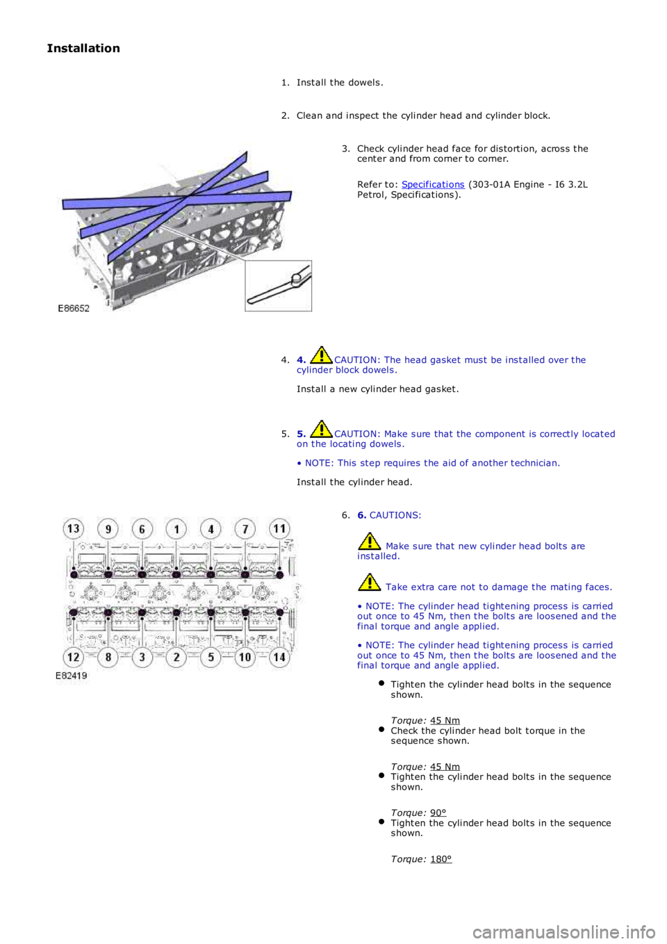
2. Check cyli nder head face for dis torti on, acros s t he
cent er and from corner t o corner.
Refer t o: Specificati ons (303-01A Engine - I6 3.2L
Petrol, Speci fi cat ions ).
3.
4. CAUTION: The head gasket mus t be i ns t alled over t he
cylinder block dowel s .
Inst all a new cyli nder head gas ket .
4.
5. CAUTION: Make s ure that the component is correct ly locat ed
on t he locati ng dowels .
• NOTE: This st ep requires t he aid of another t echnician.
Inst all t he cyl inder head.
5. 6.
CAUTIONS: Make s ure that new cyli nder head bolt s are
i ns t alled. Take extra care not t o damage t he mati ng faces .
• NOTE: The cylinder head ti ght ening proces s is carri ed
out once to 45 Nm, then t he bolt s are loos ened and t he
final torque and angle appl ied.
• NOTE: The cylinder head ti ght ening proces s is carri ed
out once to 45 Nm, then t he bolt s are loos ened and t he
final torque and angle appl ied.
Tight en the cyli nder head bolt s in the sequence
s hown.
T orque: 45 Nm Check the cyli nder head bolt t orque in the
s equence s hown.
T orque: 45 Nm Tight en the cyli nder head bolt s in the sequence
s hown.
T orque: 90° Tight en the cyli nder head bolt s in the sequence
s hown.
T orque: 180° 6.
Page 722 of 3229
P ubl ished: 23-Aug-2011
Engine - I6 3.2L Petrol - Crankshaft Main Bearing Carrier
Re moval and Inst a llat ion
Spe cia l T ool(s) 303-1219
Locking Tool, Cra nks ha ft 303-1278
Aligner, Timing Cove r 303-1280
Remover, Oil P ump Pi n 303-1284
Torx Socket , Acces sory Drive P ulle y
Removal
• NOTE: Re moval st eps in t his procedure may cont ai n inst all at ion det a ils.
• NOTE: Some variat ion in t he illust ra ti ons ma y occur, but t he e ss enti al informat ion is a lways corre ct .
1. W ARNING: Do not work on or under a ve hicle s upport e d only by a jack.
Always s upport t he ve hicle on s afet y st ands .
Rais e a nd s upport t he ve hicle.
1. 2. W ARNING: Avoi d skin cont act wit h t he s pe ci fied mat e rial.
• CAUTIONS: Hot flui d.
Be pre pa red t o collect es ca ping fluids .
T orque : 38 Nm Re move a nd dis ca rd t he sea ling was her.2.
Refe r t o: Engine (303-01A Engi ne - I6 3.2L Pet rol, Removal).
3.
Page 724 of 3229
8.
NOTE: Some varia t ion in t he illust rat ions may occur, but t he e ss ent ia l
inf orma t ion is a lways correct .
If t he locking pin on t he s pe cia l t ool is dis engage d, t he
cranks haft can be rota t ed.
Spec ial T ool(s ): 303-1219 8.
T orque :
10 Nm 9.
T orque :
47 Nm 10.
T orque :
10 Nm 11.
Page 734 of 3229

Publi s hed: 11-May-2011
Engine - I6 3.2L Petrol - Rear End Accessory Drive (READ) Idler Shaft
Assembly
Removal and Inst all ati on
Special T ool(s) 303-1486
Mandrel 303-1488
Rear End Acces sory Drive (READ) Idler Shaft As s embl y Extract or
Removal
• NOTE: Removal s t eps in t his procedure may cont ain i nst all ati on det ail s.
Refer t o: Specificati ons (414-00 Bat tery and Charging Sys tem -
General Informat ion, Specificati ons).
1.
2. W ARNING: Do not work on or under a vehi cle s upported onl y
by a jack. Al ways support t he vehi cl e on s afet y s tands .
Rais e and s upport t he vehi cl e.
2.
Refer t o: Rear End Acces s ory Drive (READ) (303-05A Access ory Dri ve
- I6 3.2L Pet rol , Removal and Ins t al lat ion).
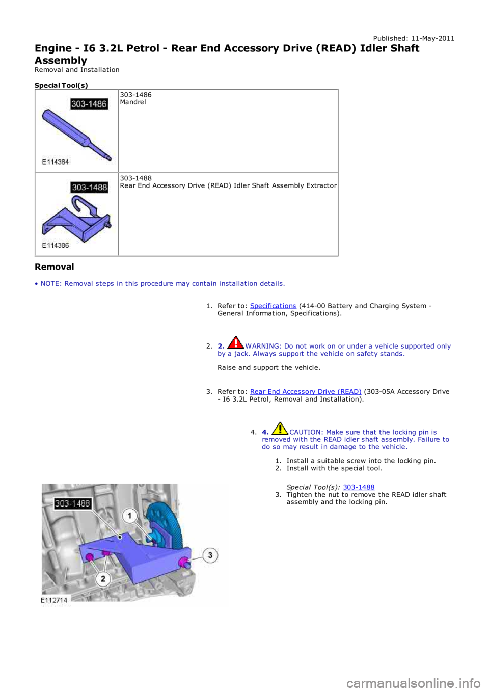
3. 4. CAUTION: Make s ure that the locki ng pin i s
removed wit h the READ idler s haft as s embly. Fai lure to
do s o may res ult i n damage to the vehicle.
Inst all a s uit able s crew int o the locki ng pin.
1.
Inst all wi th t he s peci al t ool.
Speci al Tool (s ): 303-1488 2.
Tight en the nut t o remove the READ idler s haft
as sembl y and t he locki ng pin.
3.
4.
Page 735 of 3229
5. CAUTION: Inspect the l ocki ng pin for damage.
If the l ocki ng pin i s broken in the engine bl ock, t he
engine block mus t be repl aced. Failure t o fol low this
i ns t ructi on may resul t in damage t o t he vehi cl e.
5.
Installation Apply a 2.5mm bead of sealant STC50550 (Loct it e
5900) to t he areas s hown.
1. 2. CAUTION: Make s ure that the mati ng faces are
clean and free of foreign materi al.
Inst all t he s eal ing was her to t he READ i dler
s haft as sembl y.
1.
Us ing a s ui table tool, deform the s eali ng was her
t o s ecure it t o t he READ i dler ass embly.
2.
2. 3. CAUTION: Make s ure that the mati ng faces are
clean and free of foreign materi al.
Speci al Tool (s ): 303-1486 3.
Refer t o: Rear End Acces s ory Drive (READ) (303-05A Access ory Dri ve
4.
Page 752 of 3229

Publi s hed: 11-May-2011
Engine - TD4 2.2L Diesel -
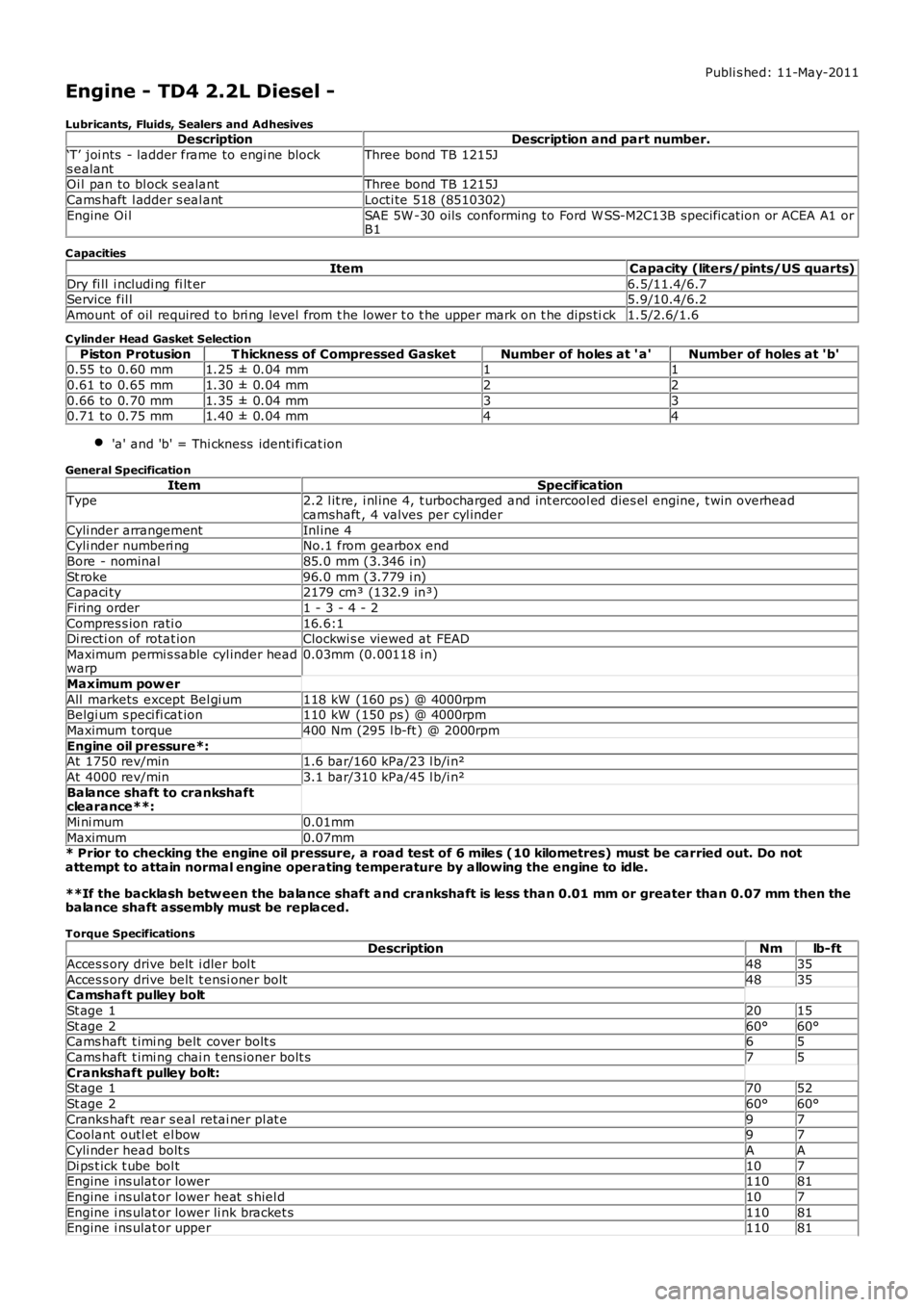
Lubricants, Fluids, Sealers and AdhesivesDescriptionDescription and part number.
‘T’ joi nts - ladder frame to engi ne blocks ealantThree bond TB 1215J
Oi l pan to bl ock s ealantThree bond TB 1215J
Cams haft l adder s eal antLocti te 518 (8510302)
Engine Oi lSAE 5W -30 oils conforming to Ford W SS-M2C13B specificat ion or ACEA A1 orB1
C apacities
ItemCapacity (liters/pints/US quarts)
Dry fi ll i ncludi ng fi lt er6.5/11.4/6.7Service fil l5.9/10.4/6.2
Amount of oil required t o bri ng level from t he lower t o t he upper mark on t he dips tick1.5/2.6/1.6
C ylinder Head Gasket Selection
Piston ProtusionT hickness of Compressed GasketNumber of holes at ' a'Number of holes at 'b'0.55 to 0.60 mm1.25 ± 0.04 mm11
0.61 to 0.65 mm1.30 ± 0.04 mm22
0.66 to 0.70 mm1.35 ± 0.04 mm330.71 to 0.75 mm1.40 ± 0.04 mm44
'a' and 'b' = Thi ckness identi fi cat ion
General Specification
ItemSpecificationType2.2 l it re, i nl ine 4, t urbocharged and int ercool ed dies el engine, t win overheadcamshaft , 4 valves per cyl inder
Cyli nder arrangementInl ine 4Cyli nder numberi ngNo.1 from gearbox end
Bore - nominal85.0 mm (3.346 i n)
St roke96.0 mm (3.779 i n)Capaci ty2179 cm³ (132.9 in³)
Firing order1 - 3 - 4 - 2
Compres s ion rati o16.6:1Di recti on of rotat ionClockwi s e viewed at FEAD
Maximum permi s sable cyl inder headwarp0.03mm (0.00118 i n)
Maximum pow er
All markets except Bel gi um118 kW (160 ps ) @ 4000rpmBelgi um s peci fi cat ion110 kW (150 ps ) @ 4000rpm
Maximum t orque400 Nm (295 l b-ft ) @ 2000rpm
Engine oil pressure*:At 1750 rev/min1.6 bar/160 kPa/23 l b/i n²
At 4000 rev/min3.1 bar/310 kPa/45 l b/i n²
Balance shaft to crankshaftclearance**:
Mi ni mum0.01mm
Maximum0.07mm* Prior to checking the engine oil pressure, a road test of 6 miles (10 kilometres) must be carried out. Do notattempt to attain normal engine operating temperature by allowing the engine to idle.
**If the backlash betw een the balance shaft and crankshaft is less than 0.01 mm or greater than 0.07 mm then thebalance shaft assembly must be replaced.
Torque SpecificationsDescriptionNmlb-ft
Acces s ory drive belt i dler bol t4835
Acces s ory drive belt t ensi oner bolt4835Camshaft pulley bolt
St age 12015
St age 260°60°Cams haft t imi ng belt cover bolt s65
Cams haft t imi ng chai n t ens ioner bolt s75
Crankshaft pulley bolt:St age 17052
St age 260°60°
Cranks haft rear s eal retai ner pl at e97Coolant outl et el bow97
Cyli nder head bolt sAA
Di ps t ick t ube bol t107Engine i ns ulat or lower11081
Engine i ns ulat or lower heat s hiel d107
Engine i ns ulat or lower li nk bracket s11081Engine i ns ulat or upper11081
Page 753 of 3229
DescriptionNmlb-ft
Engine mount bracket LH:
M8*2518M12*8059
Engine mount bracket RH:
M12*8059M14*175129
Engine mount LH bolt175129
Engine mount RH bol ts8059Flywheel bol tsAA
Fuel i njector wi ri ng harness bol t107
Fuel fil ter bracket bol ts2518Intake manifold runner control (IMRC) act uat or bol t107
Intake manifold adaptor and t hrot tl e hous i ng bol t65
Intake manifold bol ts97Lifti ng bracket s107
Oi l cooler brackets107
Oi l cooler t o cyl inder block bol ts2015Oi l fil ler t ube97
Oi l pan drain pl ug2015
Oi l pan bol ts97Oil pan extension panel:
St age 1107
St age 21612Oil pump bolts:97
St age 175
St age 297Oi l separat or bol ts75
Oi l level s ensor86
Pis t on cool ing jet bol t107Timing belt t ensi oner bolt2518
Timing belt i dler pulley bol t6044
Timing belt rear cover64Valve cover bol ts107
Vacuum pump bolt s97
* New nuts/bolts must be fitted
A = refer to procedure for correct torque sequence
Page 755 of 3229

s ecurel y bolt ed to the top of a machined cas t-iron cyl inder block. The cylinder head provides t he locati on for t he 16 valves(4 per combus ti on chamber), valve operat ing gear, cams haft s and ti ming gear, fuel inject ors and glow plugs. Dril li ngs andgalleries are formed wi thi n the cyli nder head t o provide lubri cat ing oi l and coolant fl ow.
The cyl inder head is formed wit h the cams haft l ower bearing cap cas t ings , and is enclos ed by a mat ing s t ructural cams haftcover wi th s eali ng gasket. The cams haft cover i s formed wi th the cams haft upper beari ng cap cas t ings , intake ai r fil li ngt racts , and port s for t he cyl inder head cover, crankcas e venti lat ion component s.
An 'L' s haped cyli nder head cover enclos es the s t ructural cams haft cover openings, and i ncorporates t he Posi ti ve Crankcas eVenti lati on Valve (PCV), s afet y val ve and crankcas e vent il ati on connecti ons .
An acous t ic engine cover i s i ns t alled above t he engi ne, and compris es a polypropylene foam layer adhered to theunders ide of a t hermo-plas ti c cover. The cover i s t uned t o abs orb and reduce engine produced nois e t o accept abl e NVHlevels . A hole formed in the rear Left-hand (LH) s ide of t he engine cover provi des the l ocat ion for the engine oi l fil ler cap.
The cyl inder block provides t he locat ion for t he cranks haft and beari ngs , oil cooling jet s, reci procat ing component s , and thecount er-bal ance s haft hous ing. Galleries and drill ings are formed in the cyli nder block for lubri cat ing oi l and coolant fl ow. Acount er-bal ance s haft hous ing i s bolt ed to the unders ide of t he cylinder block and is gear dri ven by the cranks haft . Thecount er-bal ance s haft as s embly reduces engine NVH to provi de a s moot h power out put .
An aluminum oi l pan hous ing and a pres sed st eel oi l pan are s ecured t o t he bot t om of t he cyl inder bl ock. The oil panhous i ng is s ealed and bol ted di rectl y to the cyli nder block. The oil pan is sealed wit h li qui d s ealant and att ached t o t he oilpan hous i ng to provide t he lubricat ion sys tem res ervoir. The lubricat ion sys tem oil pump i s l ocated ins ide t he oil pan andis bol ted t o t he unders ide of t he cyl inder bl ock. The oil pump is chain driven by t he cranks haft .
Engi ne cool ing i s achi eved wit h a pres s uri zed water-cool ant sys tem. An engi ne dri ven coolant pump dis t ri but es t he cool antt hrough gal leries in the cyli nder head and block.
Engi ne produced emis s ions comply wi th European Commis s ion Di recti ve (EUCD) St age 4 legis l at ive requirement s . Theli mit ing of res ul tant emi ss i on pol lut ant s i s acheived by us e of an exhaus t s yst em cat alyti c convert er, an opt ional Di eselPart iculate Filt er (DPF), advanced el ect ronic engine management cont rol , PCV, and Exhaus t Gas Recircul at ion (EGR)s ys t em.
ENGINE STRUCTURE