2006 LAND ROVER FRELANDER 2 lock
[x] Cancel search: lockPage 571 of 3229
Publi s hed: 11-May-2011
Steering Column - Steering Column
Des cript ion and Operat ion
COMPONENT LOCATION
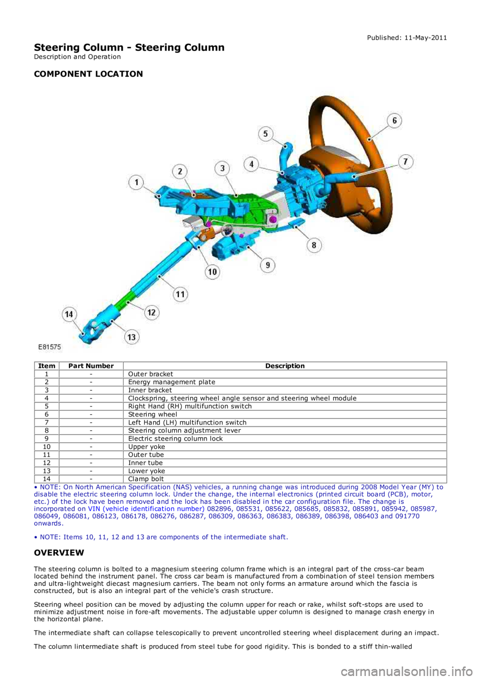
ItemPart NumberDescription
1-Out er bracket2-Energy management plat e
3-Inner bracket
4-Cl ocks pri ng, s t eering wheel angl e s ensor and s teering wheel modul e5-Ri ght Hand (RH) mul ti functi on swit ch
6-St eeri ng wheel
7-Left Hand (LH) mul ti funct ion swi tch8-St eeri ng col umn adjus tment l ever
9-El ect ri c s teeri ng column l ock
10-Upper yoke11-Out er tube
12-Inner tube
13-Lower yoke14-Cl amp bolt
• NOTE: On North Ameri can Specificat ion (NAS) vehi cles , a running change was int roduced during 2008 Model Y ear (MY ) t odis able t he electric st eering col umn lock. Under t he change, the i nternal elect ronics (print ed circuit board (PCB), motor,etc.) of t he l ock have been removed and t he lock has been dis abled i n t he car configurat ion fi le. The change i sincorporat ed on VIN (vehi cl e identi fi cat ion number) 082896, 085531, 085622, 085685, 085832, 085891, 085942, 085987,086049, 086081, 086123, 086178, 086276, 086287, 086309, 086363, 086383, 086389, 086398, 086403 and 091770onwards .
• NOTE: Items 10, 11, 12 and 13 are components of t he i nt ermedi ate s haft .
OVERVIEW
The s teeri ng column i s bolt ed to a magnesi um s t eering column frame whi ch is an i ntegral part of t he cros s -car beamlocated behind the i nst rument panel. The cros s car beam is manufact ured from a combinati on of s teel tens ion membersand ult ra-li ght weight diecas t magnes ium carri ers . The beam not onl y forms an armature around whi ch the fasci a iscons t ructed, but is al so an int egral part of the vehicle's crash s truct ure.
Steering wheel pos it ion can be moved by adjust ing the column upper for reach or rake, whi ls t s oft -s tops are us ed tomi ni mi ze adjust ment nois e i n fore-aft movement s. The adjus t abl e upper column is des igned t o manage cras h energy i nt he horizontal plane.
The int ermediat e s haft can collaps e t eles copicall y to prevent uncont rol led s t eering wheel dis placement during an i mpact .
The col umn l int ermediat e s haft is produced from s teel tube for good rigi dit y. This is bonded to a s ti ff t hin-wal led
Page 585 of 3229

Publi s hed: 11-May-2011
Steering Column Switches - Steering Column Switches
Des cript ion and Operat ion
COMPONENT LOCATION
ItemPart NumberDescription
1-Speed cont rol s wit ches2-St eering column cas e containi ng the mult ifunct ion s wit ches and cl ocks pring
3-Audio control swit ches
OVERVIEW
The winds hield wiper s wit ch is l ocat ed in the right -hand-s ide of t he cas e and retai ned wit h 2 s crews . The s wit ch isconnected t o t he mai n harness vi a a connect or at the back of the s wi tch. The s wit ch cont rols the followi ng functi ons :
W i nds hiel d wi per i nt ermit tent s low and fas t speedW i nds hiel d wi per fli ck wipeW i nds hiel d was h/wi peRear was h/wipeInt ermit tent delay s electi on.
The t urn s ignal indicator s wit ch is locat ed i n t he left -hand-si de of the cas e and ret ained wi th 2 s crews . The swi tch i sconnected t o t he mai n harness vi a a connect or on the back of t he swit ch. The s wit ch cont rol s the foll owing funct ions:
Left / right turn s ignal operati onHigh / low beam operati onHeadl amp flas hTri p comput er functi on s el ect ion (i f fit t ed).
The t rip but t on allows the driver to cycle t hough an opti on menu and als o reset t ri p cycl e mi leage cal cul ati ons . The t ripcomput er informat ion i s dis played in the i nst rument clus ter mes s age cent er (high line ins trument cl us t er onl y).
Steering wheel mount ed s wit ches on the right -hand-s ide of t he dri ver's ai rbag, cont rol the audi o and tel ephone funct ions.Swit ches on the l eft -hand-s ide of t he dri ver's ai rbag control t he s peed cont rol functi ons .
The clocks pri ng is locat ed i n the front of t he cas e and retai ned wit h four s crews . The clocks pri ng engages i n s lots in t hes teeri ng wheel bos s and t urns wi th the rotat ion of t he s teeri ng wheel. The clocks pring incorporat es a t ang which cancelst he turn s ignal indicators when the st eering wheel i s rot ated.For addit ional informat ion, refer t o: Air Bag and Safet y Belt Pretens ioner Supplement al Res traint Syst em (SRS) (501-20BSuppl ement al Rest rai nt Sys tem, Des cri pti on and Operati on).
CONTROL DIAGRAM
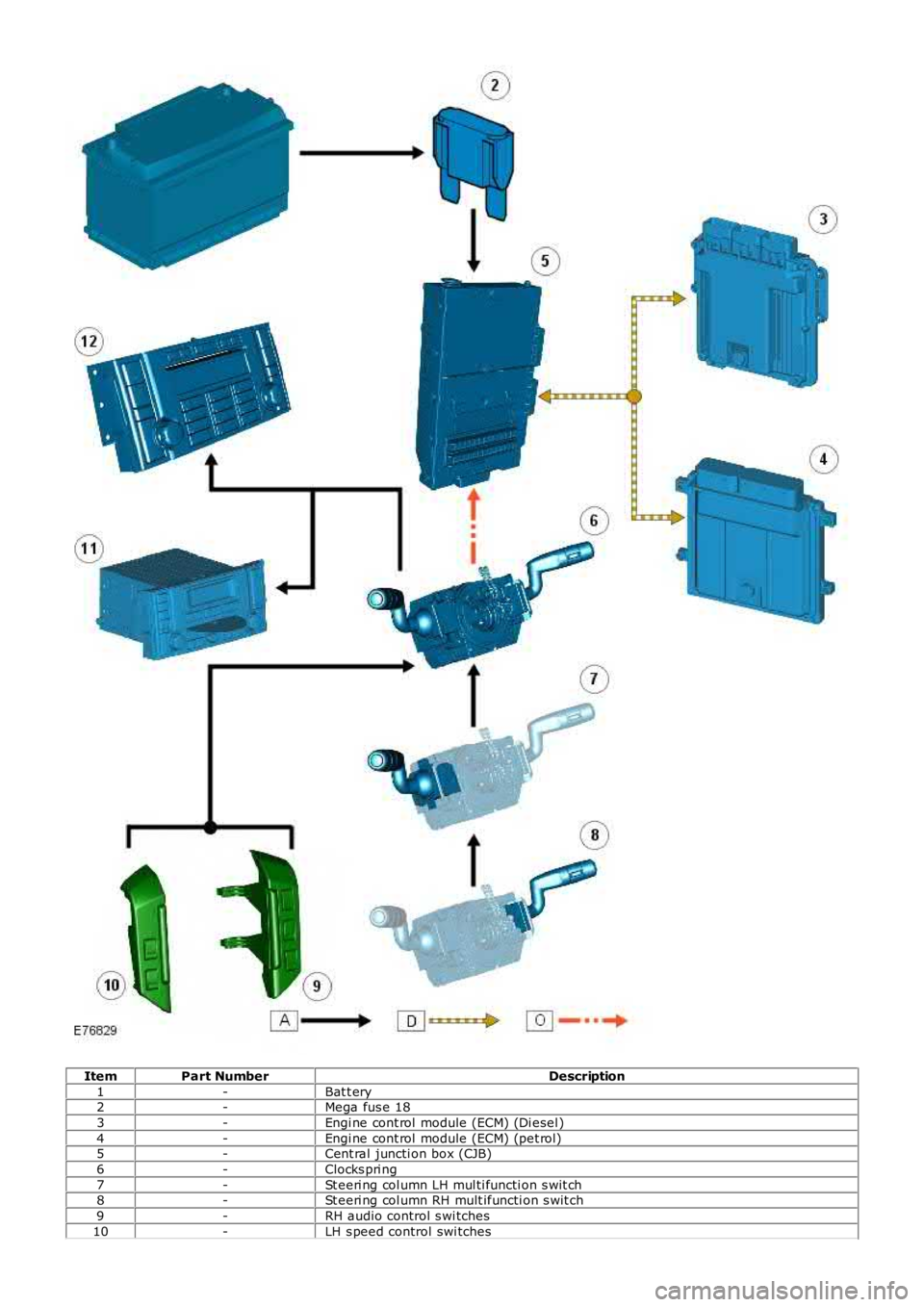
• NOTE: A = Hardwi red; D = Hi gh s peed CAN bus , O = LIN bus
Page 586 of 3229
ItemPart NumberDescription
1-Bat t ery2-Mega fus e 18
3-Engi ne cont rol module (ECM) (Di esel )
4-Engi ne cont rol module (ECM) (pet rol)5-Cent ral juncti on box (CJB)
6-Clocks pri ng
7-St eeri ng col umn LH mul ti functi on s wit ch8-St eeri ng col umn RH mult ifuncti on s wit ch
9-RH audio control s wi tches
10-LH s peed control swi tches
Page 589 of 3229

1-Pres s t o s wit ch between radi o, CD, or AUX
2-Pres s t o i ncreas e volume
3-Pres s t o decrease vol ume4-Pres s and release to scrol l through preset radi o s t at ions or CD tracks . Pres s to search up or down fort he next or previous radio s t at ion/CD t rack
The audi o control s wi tches are res is ti ve ladder swi tches. Thes e s wit ches connect t o t he Infotainment Control Modul e (ICM)or Int egrated Audi o Modul e (IAM) (dependant upon the l evel of audi o fit ted t o t he vehicle) via t he clockspring.
For addit ional informat ion, refer t o: Audi o Sys tem (415-01, Des cript ion and Operat ion).
Speed Control Switches
ItemPart NumberDescription
1-Set t arget speed, or increase s peed
2-Set t arget speed, or decreas e s peed3-Res ume s et s peed
4-Cancel s s peed cont rol operati on wit hout erasi ng memorized s peed
The s peed control swit ches are res is t ive l adder type. The s ignals from the res is ti ve ladder are fed t o the st eeri ng col umnmodule (located in t he clocks pri ng) which t hen out put s t he s ignals as a local i nterconnect net work (LIN) bus s ignal to thecent ral junct ion box (CJB). The CJB trans mi ts speed cont rol s ignals on the hi gh s peed controll er area network (CAN) bus t ot he engi ne cont rol module (ECM).
For addit ional informat ion, refer t o: Speed Cont rol (310-03A Speed Cont rol - I6 3.2L Petrol, Des cript ion and Operat ion).
For addit ional informat ion, refer t o: Speed Cont rol - 2.2L Di esel (310-03, Des cri ption and Operati on).
Page 596 of 3229
Publi s hed: 11-May-2011
Steering Column Switches - Steering Column Lock Module
Removal and Inst all ati on
Removal
• NOTE: On vehicles bui lt from VIN 091770 t he s teeri ng col umn l ock modul e may be a non-functi onal component .
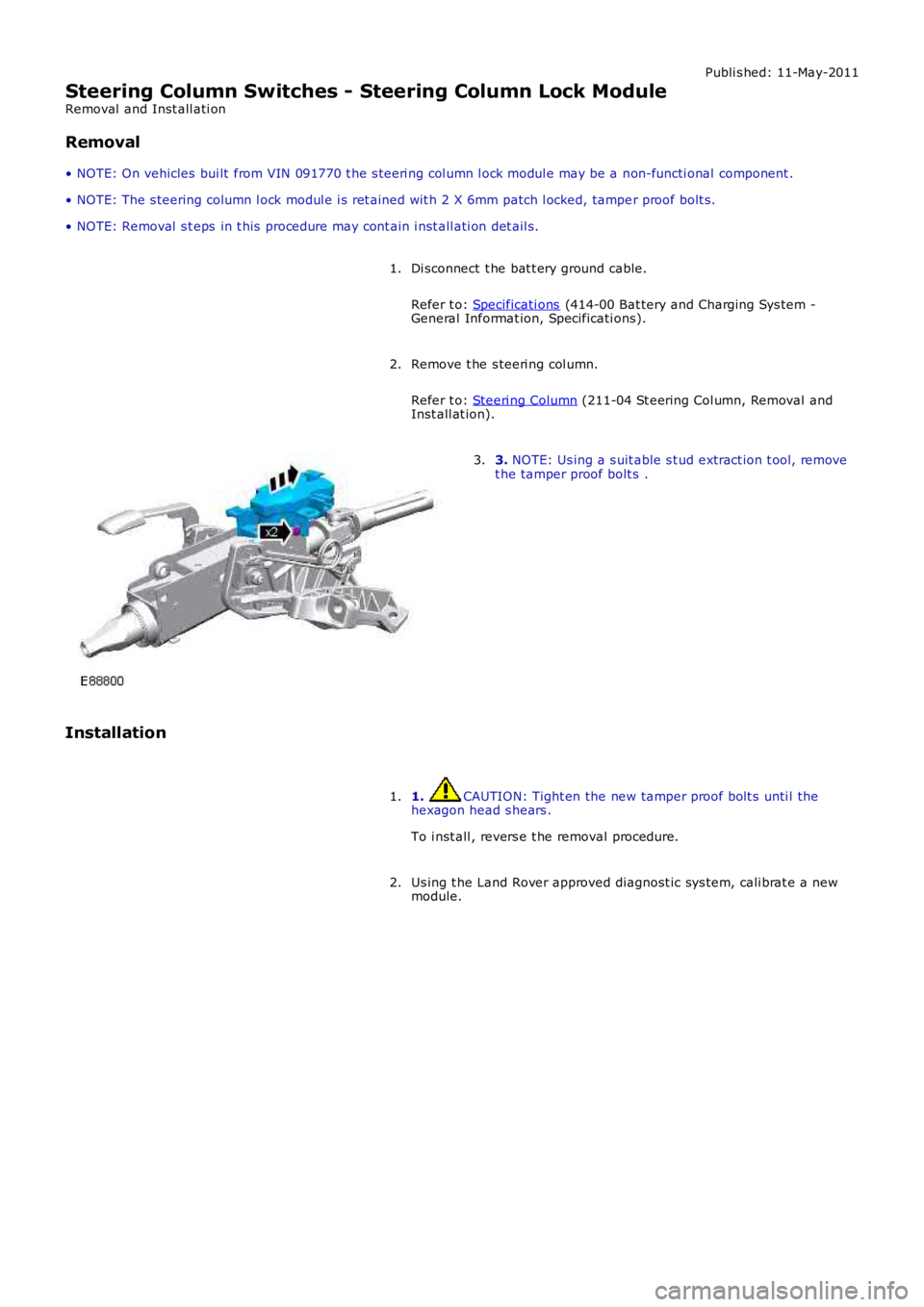
• NOTE: The s teering column l ock modul e i s ret ained wit h 2 X 6mm patch l ocked, tamper proof bolt s.
• NOTE: Removal s t eps in t his procedure may cont ain i nst all ati on det ail s.
Di sconnect t he bat t ery ground cable.
Refer t o: Specificati ons (414-00 Bat tery and Charging Sys tem -General Informat ion, Specificati ons).
1.
Remove t he s teeri ng col umn.
Refer t o: Steeri ng Column (211-04 St eering Col umn, Removal andInst all at ion).
2.
3. NOTE: Us ing a s uit able s t ud extract ion t ool, removet he tamper proof bolt s .3.
Installation
1. CAUTION: Tight en the new tamper proof bolt s unti l thehexagon head s hears .
To i nst all , revers e t he removal procedure.
1.
Us ing t he Land Rover approved diagnost ic sys tem, cali brat e a newmodule.2.
Page 598 of 3229
Publi s hed: 11-May-2011
Engine System - General Information - Cylinder Head Gasket SelectionTD4
2.2L Diesel
General Procedures
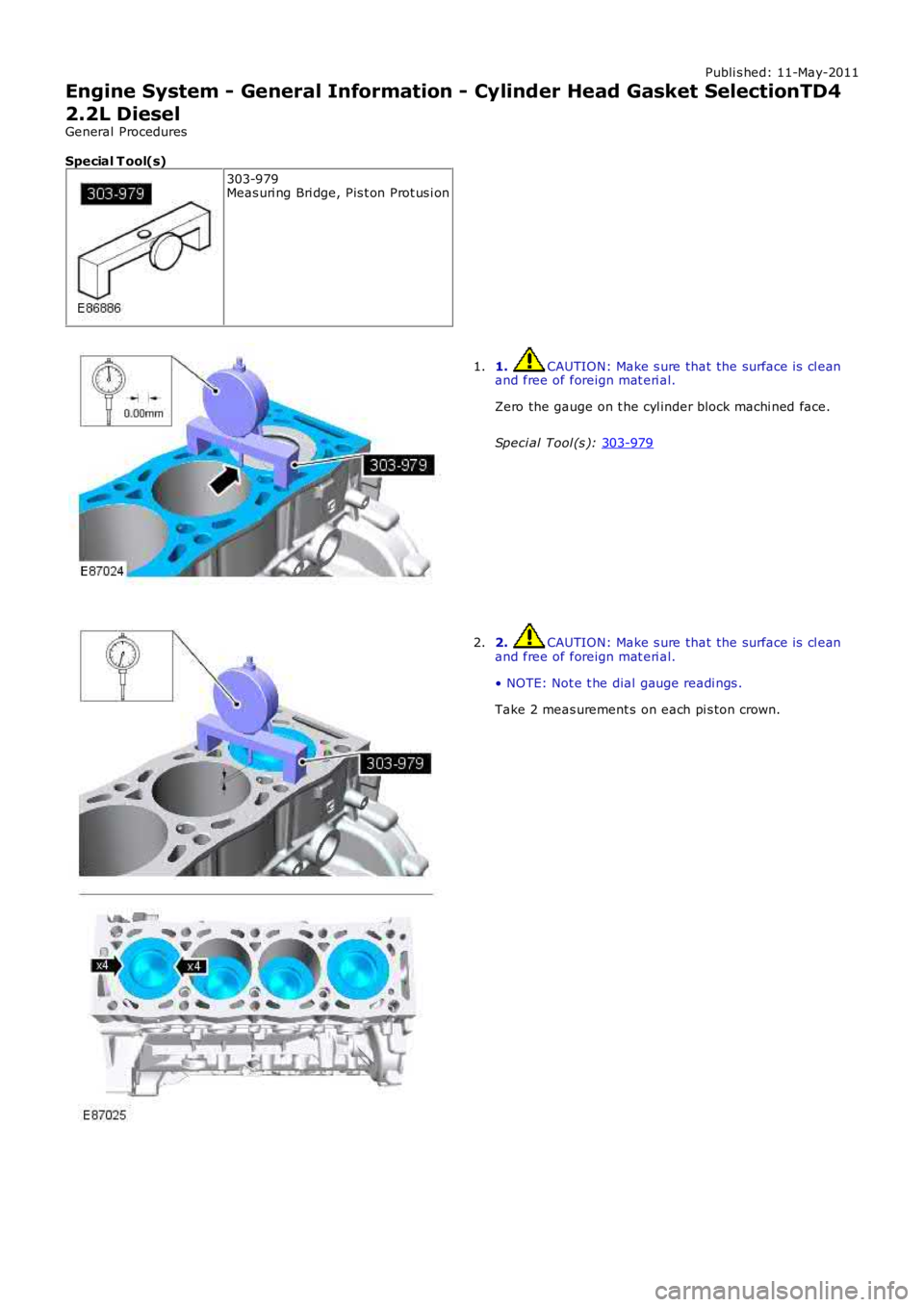
Special T ool(s) 303-979
Meas uri ng Bri dge, Pis t on Prot us i on 1. CAUTION: Make s ure that the surface is cl ean
and free of foreign mat eri al.
Zero the gauge on t he cyl inder block machi ned face.
Speci al Tool (s ): 303-979 1.
2. CAUTION: Make s ure that the surface is cl ean
and free of foreign mat eri al.
• NOTE: Not e t he dial gauge readi ngs .
Take 2 meas urement s on each pi s ton crown.
2.
Page 603 of 3229
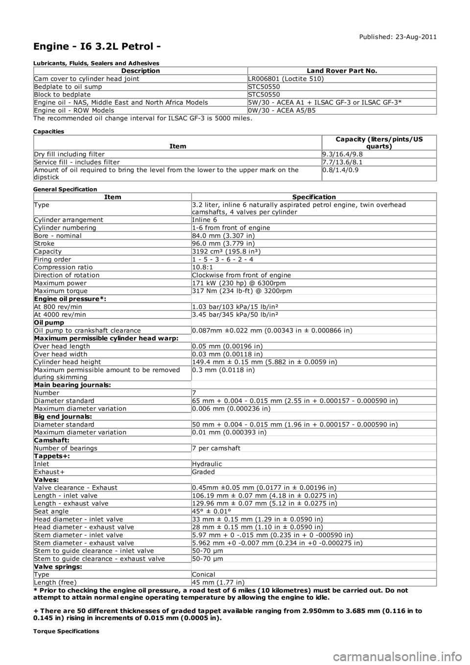
Publi s hed: 23-Aug-2011
Engine - I6 3.2L Petrol -
Lubricants, Fluids, Sealers and AdhesivesDescriptionLand Rover Part No.
Cam cover to cyli nder head jointLR006801 (Loct it e 510)
Bedplate to oi l s umpSTC50550Block t o bedpl ateSTC50550
Engine oil - NAS, Mi ddl e Eas t and Nort h Africa Models5W /30 - ACEA A1 + ILSAC GF-3 or ILSAC GF-3*
Engine oil - ROW Models0W /30 - ACEA A5/B5The recommended oil change i nterval for ILSAC GF-3 is 5000 mi les .
C apacities
ItemCapacity (liters/pints/USquarts)
Dry fi ll i ncludi ng fi lt er9.3/16.4/9.8
Service fil l - includes fi lt er7.7/13.6/8.1Amount of oil required t o bri ng the level from the lower to the upper mark on thedips t ick0.8/1.4/0.9
General Specification
ItemSpecificationType3.2 li ter, inli ne 6 nat urall y aspi rat ed pet rol engine, twi n overheadcams haft s, 4 val ves per cylinderCyli nder arrangementInli ne 6
Cyli nder numberi ng1-6 from front of engine
Bore - nominal84.0 mm (3.307 in)St roke96.0 mm (3.779 in)
Capaci ty3192 cm³ (195.8 i n³)
Firing order1 - 5 - 3 - 6 - 2 - 4Compres s ion rati o10.8:1
Di recti on of rotat ionCl ockwis e from front of engi ne
Maximum power171 kW (230 hp) @ 6300rpmMaximum t orque317 Nm (234 lb-ft ) @ 3200rpm
Engine oil pressure*:
At 800 rev/min1.03 bar/103 kPa/15 lb/in²At 4000 rev/min3.45 bar/345 kPa/50 lb/in²
Oil pump
Oi l pump to cranks haft clearance0.087mm ±0.022 mm (0.00343 i n ± 0.000866 i n)Maximum permissible cylinder head w arp:
Over head length0.05 mm (0.00196 i n)
Over head widt h0.03 mm (0.00118 i n)Cyli nder head height149.4 mm ± 0.15 mm (5.882 in ± 0.0059 i n)
Maximum permi s si ble amount t o be removedduri ng s ki mmi ng0.3 mm (0.0118 in)
Main bearing journals:
Number7
Di amet er s tandard65 mm + 0.004 - 0.015 mm (2.55 in + 0.000157 - 0.000590 in)Maximum diamet er variat ion0.006 mm (0.000236 in)
Big end journals:
Di amet er s tandard50 mm + 0.004 - 0.015 mm (1.96 in + 0.000157 - 0.000590 in)Maximum diamet er variat ion0.01 mm (0.000393 i n)
Camshaft:
Number of bearings7 per cams haftT appets+:
InletHydrauli c
Exhaus t +GradedValves:
Valve clearance - Exhaus t0.45mm ±0.05 mm (0.0177 in ± 0.00196 in)
Lengt h - i nlet valve106.19 mm ± 0.07 mm (4.18 in ± 0.0275 i n)Lengt h - exhaus t valve129.96 mm ± 0.07 mm (5.12 in ± 0.0275 i n)
Seat angl e45° ± 0.01°
Head diamet er - inlet valve33 mm ± 0.15 mm (1.29 in ± 0.0590 i n)Head diamet er - exhaus t val ve28 mm ± 0.15 mm (1.10 in ± 0.0590 i n)
St em diamet er - inlet valve5.97 mm + 0 -.015 mm (0.235 in + 0 -000590 i n)
St em diamet er - exhaus t val ve5.962 mm +0 -0.007 mm (0.234 in +0 -0.000275 i n)St em t o guide clearance - i nlet val ve50-70 µm
St em t o guide clearance - exhaus t valve50-70 µm
Valve springs:TypeConical
Lengt h (free)45 mm (1.77 in)
* Prior to checking the engine oil pressure, a road test of 6 miles (10 kilometres) must be carried out. Do notattempt to attain normal engine operating temperature by allowing the engine to idle.
+ T here are 50 different thicknesses of graded tappet available ranging from 2.950mm to 3.685 mm (0.116 in to0.145 in) rising in increments of 0.015 mm (0.0005 in).
Torque Specifications
Page 604 of 3229
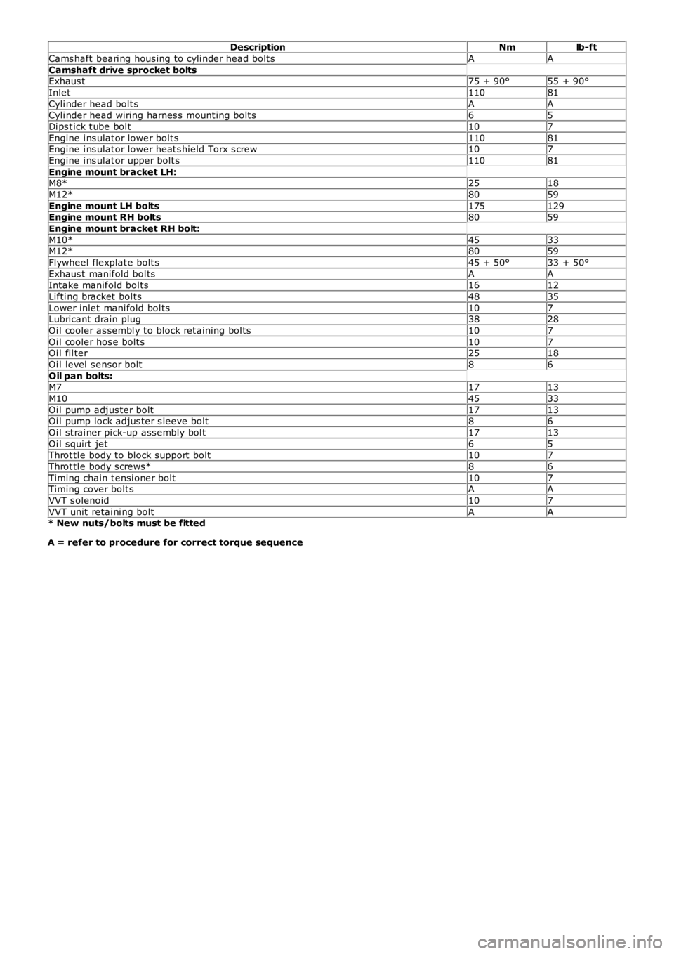
DescriptionNmlb-ft
Cams haft beari ng hous ing to cyli nder head bolt sAA
Camshaft drive sprocket boltsExhaus t75 + 90°55 + 90°
Inlet11081
Cyli nder head bolt sAACyli nder head wiring harnes s mount ing bolt s65
Di ps t ick t ube bol t107
Engine i ns ulat or lower bolt s11081Engine i ns ulat or lower heat s hield Torx s crew107
Engine i ns ulat or upper bolt s11081
Engine mount bracket LH:M8*2518
M12*8059
Engine mount LH bolts175129Engine mount RH bolts8059
Engine mount bracket RH bolt:
M10*4533M12*8059
Flywheel flexplat e bolt s45 + 50°33 + 50°
Exhaus t manifold bol tsAAIntake manifold bol ts1612
Lifti ng bracket bol ts4835
Lower inlet mani fold bol ts107Lubricant drain plug3828
Oi l cooler as sembl y t o block ret aining bol ts107
Oi l cooler hos e bolt s107Oi l fil ter2518
Oi l level s ensor bolt86
Oil pan bolts:M71713
M104533
Oi l pump adjus ter bolt1713Oi l pump lock adjus ter s leeve bolt86
Oi l st rai ner pi ck-up ass embly bol t1713
Oi l squirt jet65Throt tl e body to block support bolt107
Throt tl e body s crews*86
Timing chain t ensi oner bolt107Timing cover bolt sAA
VVT s olenoid107
VVT unit retai ni ng boltAA* New nuts/bolts must be fitted
A = refer to procedure for correct torque sequence