Page 617 of 3229
The chill cas t cylinder head is of t he cros s-flow t ype, manufact ured from a light-alloy met al. Deep-s eat ed bolt s, to reducedis tortion, s ecure t he cylinder head t o t he cylinder block. Two hollow locat ing dowels align the cylinder head wit h t he cylinderblock. The 2 cams haft s are supported by 7 bearing caps each, direct ly in t he cylinder head and cams haft cover.
Cylinder Head Gasket
ItemPart NumberDescription1-Cylinder head gasketThe s eal bet ween the cylinder head and cylinder block is a conventional cylinder head gas ket . The head gasket is made of s t eeland has multiple layers . For s ervice, t here is only 1 s iz e of gas ket available.
Oil Separation Housing
Page 618 of 3229
ItemPart NumberDescription1-O il s eparat ion housingCrankcas e gas es are rout ed from t he crankcas e, engine block and cylinder head t o t he oil s eparat ion hous ing locat ed on t hecams haft cover. From the oil s eparat ion housing, t he crankcas e gas es are rout ed via a pres sure regulat or, locat ed at t he rear edgeof the hous ing, to the cylinder head and the intake port s for t he int ake valves .For addit ional information, refer t o: Evaporative Emis sions (303-13 Evaporative Emis sions , Descript ion and O perat ion).
Camshaft Housing
Page 620 of 3229

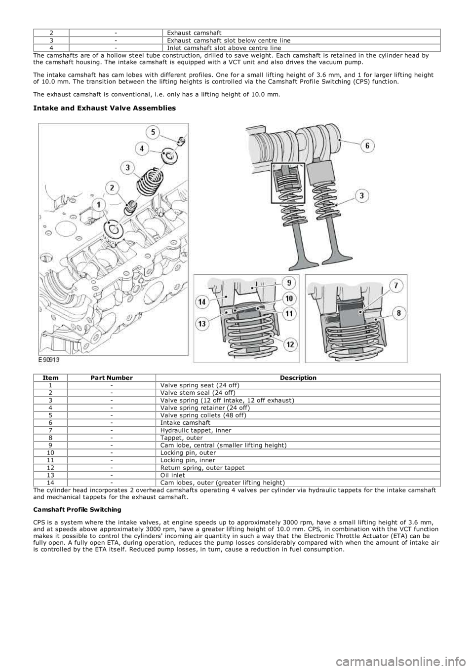
2-Exhaust camshaft3-Exhaust camshaft slot below cent re line4-Inlet camshaft slot above cent re lineThe cams hafts are of a hollow st eel t ube cons t ruction, drilled t o s ave weight . Each camshaft is ret ained in t he cylinder head bythe cams haft hous ing. The int ake cams haft is equipped wit h a VCT unit and also drives the vacuum pump.
The intake camshaft has cam lobes wit h different profiles. One for a small lift ing height of 3.6 mm, and 1 for larger lift ing heightof 10.0 mm. The t ransit ion bet ween t he lift ing height s is cont rolled via the Cams haft Profile Swit ching (CPS) funct ion.
The exhaus t cams haft is convent ional, i.e. only has a lifting height of 10.0 mm.
Intake and Exhaust Valve Assemblies
ItemPart NumberDescription1-Valve s pring s eat (24 off)2-Valve s t em s eal (24 off)3-Valve s pring (12 off int ake, 12 off exhaus t )4-Valve s pring ret ainer (24 off)5-Valve s pring collets (48 off)6-Intake camshaft7-Hydraulic t appet , inner8-Tappet , outer9-Cam lobe, central (s maller lift ing height)10-Locking pin, out er11-Locking pin, inner12-Ret urn s pring, outer tappet13-O il inlet14-Cam lobes , outer (great er lift ing height )The cylinder head incorporat es 2 overhead camshaft s operating 4 valves per cylinder via hydraulic t appet s for the intake camshaftand mechanical t appets for the exhaust cams haft .
Camshaft Profile Sw itching
CPS is a sys tem where t he int ake valves , at engine s peeds up to approximat ely 3000 rpm, have a s mall lifting height of 3.6 mm,and at s peeds above approximat ely 3000 rpm, have a great er lift ing height of 10.0 mm. CPS, in combinat ion wit h t he VCT funct ionmakes it poss ible to cont rol t he cylinders' incoming air quant it y in s uch a way that t he Electronic Throt t le Act uat or (ETA) can befully open. A fully open ETA, during operat ion, reduces t he pump los s es cons iderably compared wit h when the amount of int ake airis controlled by t he ETA its elf. Reduced pump los s es , in turn, cause a reduction in fuel consumpt ion.
Page 621 of 3229

ItemPart NumberDescription1-O ut er t appet2-Locking pin, outer3-Inner t appet4-Locking pin wit h s pring, inner5-O il inlet , hydraulic valve adjus tment6-Hydraulic valve adjus tment unit7-Return s pring, out er t appet8-Lug9-O il inlet , CPS functionThe elect rical hydraulic valves are seat valves .
The valves have 3 input s /outputs :
Inlet , oil s upplyTo/from tappetTo return, i.e. oil pan
A s olenoid is affected via an elect ro-magnet, which affect s a valve t hat can as sume 2 pos itions .
W hen the s olenoid is not activat ed, t he valve is only affect ed by the oil pres s ure on the intake s ide. The valve clos es for int akebut opens bet ween t he t appet and return.
The oil pres sure is low at t he t appet 's out er locking pin and t he valves lift a s mall amount .
W hen the s olenoid is act ivated, t he valve is affected from above by an elect ro-magnet that overpowers t he force of t he oilpress ure.
The valve s hift s posit ion and clos es bet ween t he tappet and ret urn but opens the connect ions between int ake and t appet .
The oil pres sure is high at t he tappet 's out er locking pin t hat is lifted and affects t he inner locking pin. Outer and inner t appetconnect and the valves lift a great er amount.
Page 622 of 3229

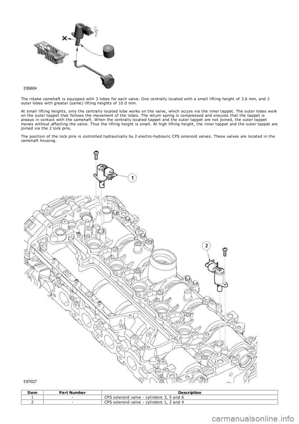
The intake camshaft is equipped wit h 3 lobes for each valve. One cent rally locat ed wit h a small lift ing height of 3.6 mm, and 2out er lobes wit h great er (s ame) lifting height s of 10.0 mm.
At small lift ing height s, only t he cent rally locat ed lobe works on t he valve, which occurs via t he inner t appet . The out er lobes workon the outer t appet t hat follows t he movement of t he lobes. The ret urn spring is compres s ed and ens ures that t he tappet isalways in cont act wit h t he camshaft . W hen the cent rally locat ed t appet and t he out er t appet are not joined, t he outer tappetmoves without affect ing the valve. Thus the lifting height is s mall. At high lift ing height, t he inner t appet and t he out er t appet arejoined via t he 2 lock pins .
The pos it ion of the lock pins is cont rolled hydraulically by 2 elect ro-hydraulic CPS solenoid valves . Thes e valves are locat ed in t hecams haft hous ing.
ItemPart NumberDescription1-CPS s olenoid valve - cylinders 3, 5 and 62-CPS s olenoid valve - cylinders 1, 2 and 4
Page 632 of 3229

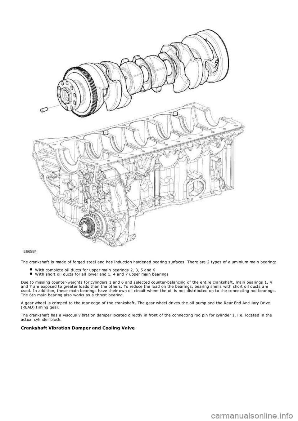
The crankshaft is made of forged s teel and has induction hardened bearing s urfaces . There are 2 types of aluminium main bearing:
W it h complet e oil duct s for upper main bearings 2, 3, 5 and 6W it h short oil ducts for all lower and 1, 4 and 7 upper main bearings
Due t o mis s ing count er-weight s for cylinders 1 and 6 and s elected count er-balancing of the entire crankshaft , main bearings 1, 4and 7 are exposed t o great er loads t han the ot hers. To reduce t he load on the bearings , bearing shells wit h s hort oil duct s areus ed. In addit ion, these main bearings have t heir own oil circuit where t he oil is not dis tribut ed on t o t he connecting rod bearings.The 6t h main bearing als o works as a t hrus t bearing.
A gear wheel is crimped to t he rear edge of the crankshaft . The gear wheel drives t he oil pump and the Rear End Ancillary Drive(READ) t iming gear.
The crankshaft has a vis cous vibration damper locat ed directly in front of t he connecting rod pin for cylinder 1, i.e. located in theact ual cylinder block.
Crankshaft Vibration Damper and Cooling Valve
Page 633 of 3229

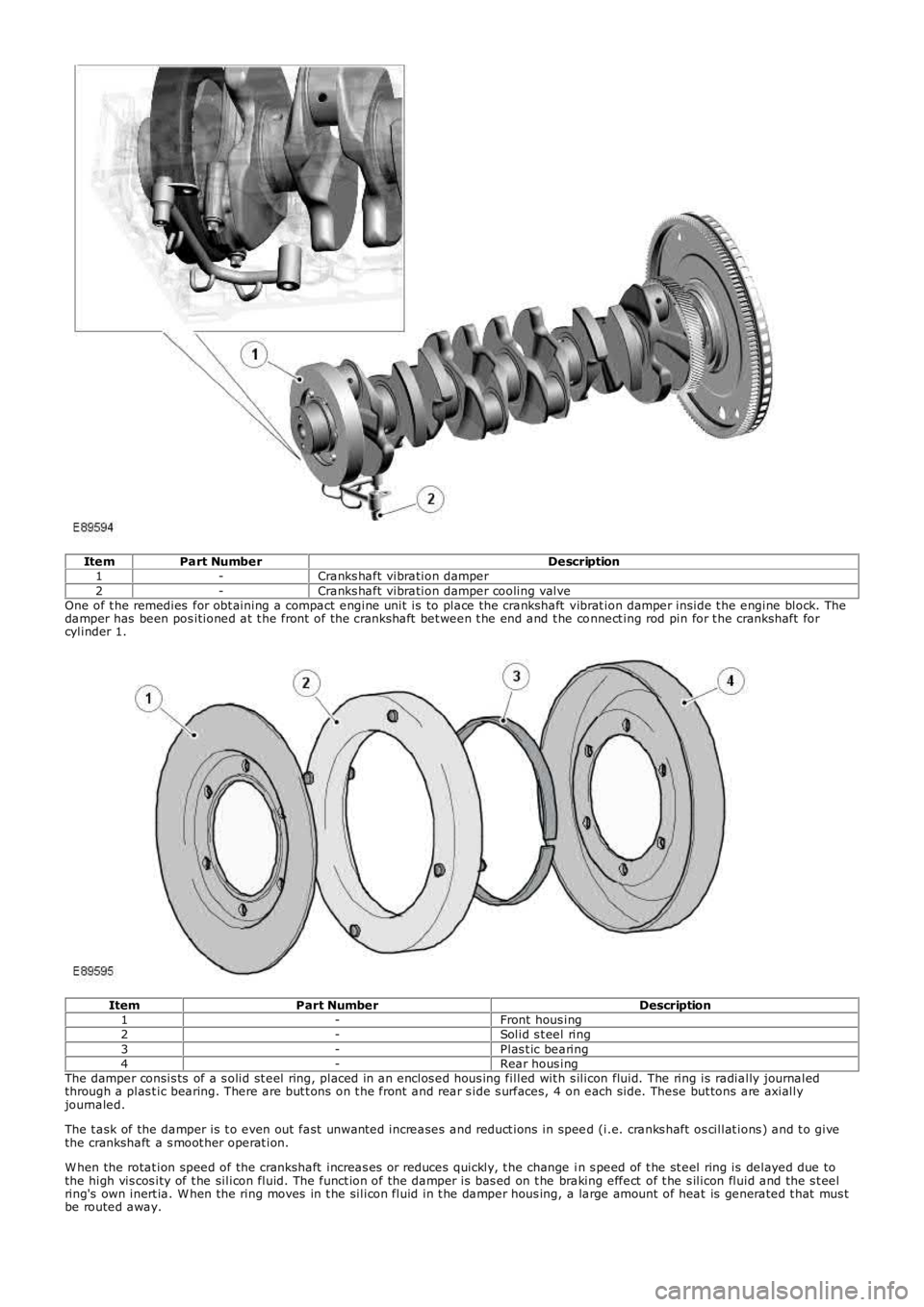
ItemPart NumberDescription1-Cranks haft vibration damper2-Cranks haft vibration damper cooling valveOne of t he remedies for obt aining a compact engine unit is to place the crankshaft vibrat ion damper inside t he engine block. Thedamper has been pos itioned at t he front of the crankshaft bet ween t he end and t he connect ing rod pin for t he crankshaft forcylinder 1.
ItemPart NumberDescription1-Front hous ing2-Solid s t eel ring3-Plas t ic bearing4-Rear hous ingThe damper consis ts of a s olid st eel ring, placed in an enclos ed hous ing filled wit h s ilicon fluid. The ring is radially journaledthrough a plas t ic bearing. There are but t ons on t he front and rear s ide s urfaces, 4 on each side. These but tons are axiallyjournaled.
The t ask of the damper is t o even out fast unwanted increases and reduct ions in speed (i.e. cranks haft os cillat ions ) and t o givethe crankshaft a s moot her operat ion.
W hen the rotat ion speed of the crankshaft increas es or reduces quickly, t he change in s peed of t he st eel ring is delayed due tothe high vis cos ity of t he silicon fluid. The funct ion of the damper is bas ed on t he braking effect of t he s ilicon fluid and the s t eelring's own inert ia. W hen the ring moves in t he silicon fluid in t he damper hous ing, a large amount of heat is generated t hat mus tbe routed away.
Page 634 of 3229
ItemPart NumberDescription1-ValveBecause the damper is locat ed in an environment where t he normal operat ing temperat ure can reach approximat ely 140°C (284°F),coupled wit h t he fact that t he damper also generates it s own heat, it is neces sary for it t o be oil cooled. A s eparat e oil circuitroutes oil from the engine's oil cooler t o a valve in t he engine block, which opens at approximat ely 2 bar. The oil t hen flows t o 3jet s, located on t he cranks haft vibrat ion damper cooling pipe, which then directs the oil t o the lower s ect ion of t he damper.
The oil flows t hrough the jets at approximately 12 lit ers per minute.
At high t emperat ures , oil cooling reduces t he damper t emperat ure by approximat ely 7°C (45°F).
Bedplate