2006 LAND ROVER FRELANDER 2 lock
[x] Cancel search: lockPage 516 of 3229

wheel i s read by the opt ical-di git al s ens ors t o produce s teeri ng wheel rotat ional speed s ignals . The s teering angle s ens oris abl e t o meas ure a rot at ion range of +/- 720 degrees , alt hough t he s teering mechani s m wi ll only al low the s t eeringwheel t o rotat e a maxi mum of +/-540 degrees .
Signals from t he st eeri ng angl e s ens or are trans mi tt ed on t he vehicle hi gh s peed CAN bus , and received and proces sed byother s yst ems s uch as DSC. The trans mi tt ed i nformat ion i ncl udes det ails of st eering wheel angle and s t eering wheelrot ati onal s peed, along wit h s ignal i ntegri ty informati on.
If a fault occurs wi thi n t he st eeri ng angl e s ens or, a DTC wi ll be s et and s tored in t he s teering angle s ens or memory. Thes teeri ng angle s ensor faul t is al s o s tored in the ABS modul e memory that i lluminates t he appropri at e warning i ndi cat orlamps , depending on the sys tem functi ons affect ed (DSC/ETC, ABS, EBA/EBD, HDC). A warni ng chi me i s als o s ounded t oalert the driver to the fault condi ti on.
For vehicles ins tall ed wit h a high-l ine i ns t rument clus ter, a mes s age is di spl ayed in t he mes sage center, onl y if t he faul taffect s t he HDC funct ion.
For addit ional informat ion, refer t o:
Ins trument Clus ter (413-01 Ins t rument Clus t er, Descripti on and Operat ion),Informat ion and Mes s age Cent er (413-08 Informati on and Mes sage Cent er, Descripti on and Operat ion).
The s teeri ng angle s ensor and ABS modul e are abl e t o be i nt errogat ed us ing t he Land Rover approved diagnos t icequi pment.
Clockspring
The clocks pri ng is a rot ary coupling that provides t he electrical connect ion bet ween the fixed s t eering wheel module, andt he st eeri ng wheel mount ed cont rols and Supplement al Res t raint Sys tem (SRS) dri ver's ai rbag.
A colored indicator i s provided wi thi n the cl ocks pring and is vis i bl e t hrough a t rans parent pers pex cover when the s t eeringwheel i s removed, and t he st eeri ng angl e s ens or is aligned t o t he cent ral posi ti on. The indicator makes s ure t he s teeringangl e s ensor and s t eering s ys tem are correct ly al igned fol lowi ng repairs t o the st eeri ng mechanis m.
Service Information
Before s eparat ing the s t eering component s from the connect ing s t eering column, t he clocks pri ng mus t be ali gned to thecent er pos i ti on (i ndi cat or vi s ible) and t he wheels point ing s t raight ahead. The clockspring i s ret ained i n the cent ralposi ti on wit h a locki ng s crew.
INSTRUMENT CLUSTER INDICATOR LAMPS
Page 517 of 3229
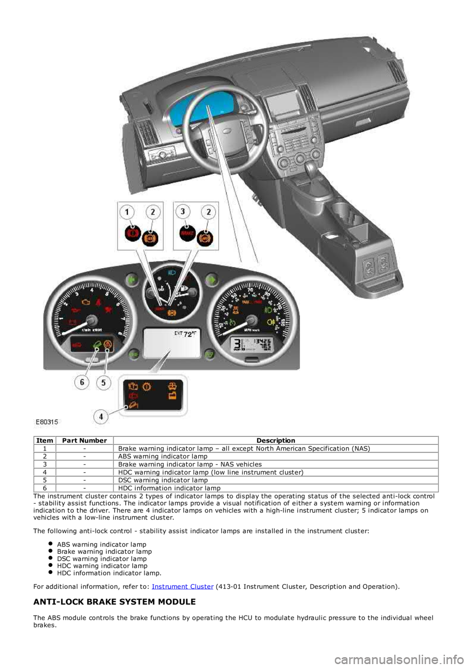
ItemPart NumberDescription
1-Brake warni ng indi cat or l amp – al l except Nort h American Specificati on (NAS)2-ABS warni ng indicator l amp
3-Brake warni ng indi cat or l amp - NAS vehicl es
4-HDC warning i ndi cat or lamp (low li ne ins trument cl ust er)5-DSC warni ng indicat or l amp
6-HDC i nformat ion indicator lamp
The ins t rument clus ter cont ains 2 types of indicator lamps to di s pl ay the operat ing st atus of t he s elected ant i-lock cont rol- s tabil it y as si s t functi ons . The indicat or l amps provide a vis ual not ifi cat ion of ei ther a s yst em warning or i nformat ionindicat ion t o t he dri ver. There are 4 indicat or l amps on vehicles wi th a high-l ine inst rument clus t er; 5 i ndi cat or lamps onvehi cl es wit h a low-line ins trument cl us t er.
The fol lowing ant i-lock cont rol - s t abi li ty as s is t indicat or l amps are ins tall ed in the ins trument cl us t er:
ABS warni ng indicat or l ampBrake warning i ndi cat or lampDSC warni ng indi cat or l ampHDC warning i ndi cat or lampHDC i nformati on indicator l amp.
For addit ional informat ion, refer t o: Ins t rument Clus ter (413-01 Inst rument Cl us t er, Des cript ion and Operat ion).
ANTI-LOCK BRAKE SYSTEM MODULE
The ABS module cont rols the brake funct ions by operat ing t he HCU to modul at e hydrauli c pres s ure t o t he indivi dual wheelbrakes.
Page 520 of 3229
25-Sol enoi d-operated inlet valve (LH rear brake)
26-Sol enoi d-operated inlet valve (RH front brake)
The HCU features 3 operati ng modes:
Normal braki ng/ EBDABS brakingActi ve braking.
Normal Braking/EBD Mod e
Ini ti ally, all of t he s olenoi d-operat ed val ves are de-energi zed. Operat ing the brake pedal produces a corres pondi ngincreas e or decreas e of press ure in t he brakes , through t he open pil ot val ves and i nlet valves. If t he ABS moduledetermines t hat EBD is necess ary, i t energi zes the i nlet valves for both the rear brakes , t o i sol at e t he brakes from anyfurther increas e i n hydraulic press ure.
• NOTE: Only the rear brakes are control led by the EBD funct ion.
ABS Braking Mode
If the ABS modul e determines t hat ABS braking i s neces sary, it energizes t he inl et and out let valves of the relat ed brakeand s tarts t he hydrauli c ret urn pump. The i nl et val ve cl oses to i s ol ate the brake from pres s uri zed flui d; the out let valveopens to releas e pres s ure from the brake int o t he accumulat or, and t he ret urn pump ci rcuit . The reduced hydraul ic pres s ureall ows the wheel t o accelerate. The ABS module then operat es the i nlet and outl et val ves t o modul at e t he pres s ure i n t hebrake t o apply t he maximum braking effort wit hout locki ng the wheel . Cont rol of the val ves for each wheel takes placeindivi dual ly.
Active Braking Mode
The act ive braki ng mode i s us ed to generat e and control hydrauli c pres s ure t o t he brakes for funct ions other t han Normaland ABS braking, for example RSC, DSC, EBA, ETC, HDC.
For act ive braking, t he ABS module energi zes the pi lot valves and pri ming valves , start s t he ret urn pump and energizes allof the inlet valves. Brake fl uid, drawn from t he res ervoir t hrough the mast er cyl inder and priming valve, is press uri zed byt he ret urn pump and suppli ed to the i nlet valves. The ABS modul e t hen operat es t he inl et valves and out let val ves , asrequired, to modul at e t he pres s ure i n t he indivi dual brakes . Some noi s e may be generat ed during act ive braki ng.
Service Information
The ABS module compris es an HCU and an Elect roni c Cont rol Unit (ECU) t hat mus t not be s eparated. The ABS module andHCU as s embly i s s uppl ied as a si ngl e component and arrives i n a pre-fill ed s tat e.
• NOTE: The ABS module, HCU and the s ens or clus t er are fragil e components and mus t be dis carded if dropped ordamaged.
CONTROL DIAGRAM
• NOTE: A = Hardwi red; D = Hi gh Speed CAN bus ; N = Medi um Speed CAN bus ; U = Pri vat e CAN bus
Page 522 of 3229

12-LH front wheel s peed s ens or
13-RH rear wheel s peed sens or
14-Act ive On-Demand Coupling modul e15-ECM
16-Diagnost ic socket
17-Sens or clus ter18-Terrai n Res pons e™ control modul e
19-Trans mis s ion Cont rol Modul e (TCM) - aut omati c t rans mis s ion models onl y
20-CJB
PRINCIPLES OF OPERATION
Anti-Lock Brake System
ABS cont rol s t he s peed of all road wheel s t o ensure opti mum wheel s li p when braking at the adhesi on li mit . The wheelsare prevent ed from locki ng to ret ai n effecti ve st eeri ng cont rol of the vehicle.
The front brake pres s ures are modul ated s eparat el y for each wheel. The rear brake press ures are modulat ed by s elect low.Select low appli es the same pres sure t o both rear brakes, wi th the press ure level bei ng det ermined by t he wheel on thelower fri ct ion s urface. This maint ai ns rear s tabil it y on s pli t fricti on s urfaces .
Corner Brake Control
CBC i nfluences the brake pres sures , below and wit hin ABS thres holds , to counteract the yawing moment produced whenbraking i n a corner. CBC produces a correcti on t orque by li mi ti ng the brake pres sure on one s ide of t he vehicle.
Dynamic Stability Control
DSC us es brakes and powert rain torque control to as s is t i n maint aining the l ateral st abi lit y of t he vehi cl e. W hil e t heignit ion is energi zed t he DSC funct ion i s permanentl y enabl ed, unl es s s elect ed off us ing t he DSC s wit ch. Even i f DSC isdesel ect ed, driving maneuvers wi th ext reme yaw or lat eral accelerat ion may trigger RSC acti vi ty to as s is t t he vehi cl es tabil it y.
DSC enhances dri ving s afet y in abrupt maneuvers and in under-st eer or over-s teer s ituat ions t hat may occur in a bend. TheABS module monit ors t he yaw rat e and l ateral accel erati on of the vehicle, s t eering input , and then s elect ively appli esindivi dual brakes and s ignals for powertrain t orque adjus t ments t o reduce under-s teer or over-s teer.
In general:
In an under-s t eer s i tuati on; the i nner wheels are braked t o count eract the yaw movement t owards t he outer edgeof the bend.In an over-st eer si tuat ion; the out er wheel s are braked to prevent t he rear end of the vehicl e from pus hing t owardst he out er edge of t he bend.
The ABS module monit ors t he tracki ng s tabil it y of the vehicle usi ng inputs from t he wheel s peed s ens ors, t he s teeringangl e s ensor, and the yaw rat e and lat eral accelerat ion sens or. The t racki ng s tabil it y is compared wit h s t ored t arget dat a.W henever t he t racki ng s tabil it y devi ates from t he target dat a, t he ABS modul e int ervenes by appl yi ng the appropriat ebrakes.
The fol lowing interact ions occur i n an i nt erventi on s it uat ion:
High speed CAN s i gnal t o t he ECM, to reduce engine torque.High speed CAN s i gnal t o t he Act ive On-demand Coupl ing module, t o open t he locki ng torque of the centercoupl ing.Applicati on of braking t o t he appropri at e corner of the vehicl e.
Electronic Brake Force Distribution
EBD l imi ts the brake press ure appl ied t o t he rear wheels . W hen t he brakes are appl ied, the wei ght of t he vehicle t rans fersforwards , reduci ng t he abi li ty of t he rear wheels to t rans fer braki ng effort t o t he road s urface. This may caus e t he rearwheels t o s li p and make t he vehi cl e uns table.
EBD us es the ant i-lock braking hardware t o automat icall y opti mize t he pres s ure of t he rear brakes , bel ow t he point whereABS i s normall y i nvoked.
• NOTE: Only the rear brakes are control led by the EBD funct ion.
Electronic Traction Control
ETC att empt s to opt imize forward tract ion by reduci ng engi ne torque, or by applying t he brake of a spi nni ng wheel unt ilt racti on is regai ned.
ETC is act ivated if an i ndi vi dual wheel speed i s above that of the vehicle reference speed (pos i ti ve sl ip) and t he brakepedal i s not pres sed. The brake i s appl ied t o t he s pinning wheel, al lowing t he excess t orque t o be t rans mit t ed to thenon-s pinning wheels through t he dri ve li ne. If neces s ary, the ABS modul e als o s ends a hi gh speed CAN bus mess age t ot he ECM t o reques t a reducti on in engine torque.
W hen t he DSC funct ion i s s elected off us i ng the DSC s wit ch, t he engi ne t orque reducti on feature i s dis abl ed.
Emergency Brake Assist
EBA as si s ts t he driver in emergency braking si tuat ions by automat icall y maximi zi ng the appl ied braki ng effort . There aret wo s it uat ions when t he ABS module wil l invoke EBA:
Page 525 of 3229
Publi s hed: 11-May-2011
Anti-Lock Control - Stability Assist - Anti-Lock Control - Stability Assist
Diagnosi s and Tes ti ng
Principles of Operation
For a detail ed descripti on of the Ant i-lock Control - St abili ty Ass i st s ys tem, refer t o the relevant Descri pti on and Operat ions ect ion i n t he works hop manual .REFER to: Ant i-Lock Control - St abili ty Ass i st (206-09C Anti -Lock Control - St abili ty Ass is t , Descripti on and Operat ion).
Inspection and Verification
CAUTION: Di agnos is by s ubs ti tut ion from a donor vehicle is NO T acceptabl e. Subs ti tut ion of cont rol modules doesnot guarant ee confirmat ion of a faul t, and may als o caus e addit ional fault s i n t he vehi cl e being t est ed and/or t he donorvehi cl e.
1. Verify t he cus t omer concern.1.
2. Vis ually ins pect for obvious s igns of mechani cal or electrical damage.2.
Visual InspectionMechanicalElectrical
St eering wheel rot ati on sens or ins tal lati on/fixingsFus esW heel s peed s ens orsConnect ors /Pi nsHarnes s esSt eering wheel rot ati on s ens or
3. If an obvious cause for an obs erved or report ed concern is found, correct t he caus e (if pos s ible) beforeproceeding t o t he next s t ep3.
4. If t he caus e is not vis ually evi dent , check for Di agnos ti c Trouble Codes (DTCs) and refer t o t he DTC Index.4.
DTC Index
• NOTE: If the control modul e or a component i s s us pect and the vehicle remains under manufacturer warrant y, refer t o theW arranty Pol icy and Procedures manual (s ect ion B1.2), or determine i f any pri or approval programme is in operat ion, pri ort o the ins tall ati on of a new module/component.
• NOTE: Generic scan t ool s may not read the codes li st ed, or may read only fi ve digit codes . Mat ch the five di git s from t hes can tool to the firs t fi ve di git s of the seven digi t code l is ted to ident ify t he faul t (t he las t t wo digi ts gi ve addi ti onalinformat ion read by the manufact urer approved diagnos t ic s ys tem).
• NOTE: W hen performing volt age or res is t ance t est s , always use a digi tal mult imeter (DMM) accurat e t o t hree deci malplaces, and wi th an up-t o-date cal ibrat ion cert ificate. W hen tes ti ng res is t ance al ways take t he res is t ance of t he DMMleads i nt o account .
• NOTE: Check and recti fy bas ic faul ts before beginni ng diagnos t ic rout ines i nvol vi ng pinpoint t es t s.
• NOTE: Ins pect connect ors for s igns of water ingres s , and pins for damage and/or corros ion.
• NOTE: If DTCs are recorded and, aft er performi ng the pi npoi nt tes ts , a fault is not present , an int ermi tt ent concern maybe t he caus e. Always check for loose connect ions and corroded terminals .
For a compl ete lis t of all Di agnos ti c Trouble Codes (DTCs) t hat could be logged on this vehicle, pleas e refer to Sect ion100-00.
REFER to: Di agnos ti c Trouble Code (DTC) Index - DTC: Steering Angle Sens or Modul e (SASM) (100-00 General Informat ion,Des cript ion and Operat ion).
Page 526 of 3229
Publi s hed: 11-May-2011
Anti-Lock Control - Stability Assist - Accelerometer
Removal and Inst all ati on
Removal
Di sconnect t he bat t ery ground cable.
Refer t o: Specificati ons (414-00 Bat tery and Charging Sys tem -
General Informat ion, Specificati ons).
1.
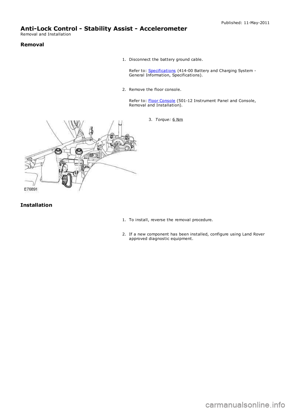
Remove t he fl oor consol e.
Refer t o: Fl oor Cons ole (501-12 Inst rument Panel and Cons ole,
Removal and Ins tall ati on).
2. T orque:
6 Nm 3.
Installation To i nst all , revers e t he removal procedure.
1.
If a new component has been ins t al led, configure usi ng Land Rover
approved diagnos t ic equipment .
2.
Page 527 of 3229
Publi s hed: 11-May-2011
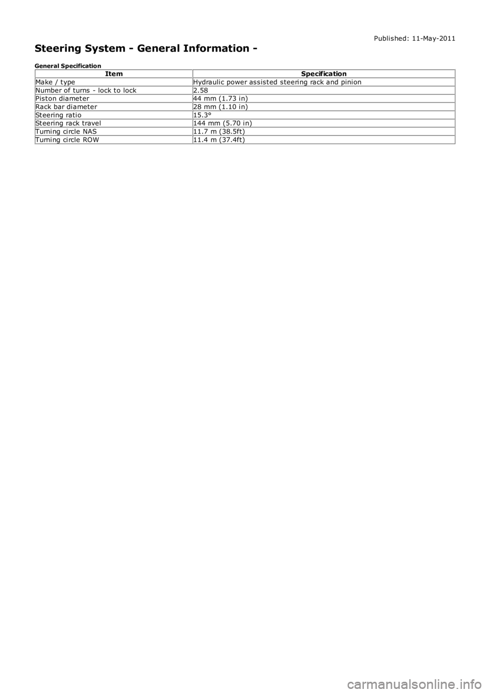
Steering System - General Information -
General SpecificationItemSpecification
Make / t ypeHydrauli c power as s is t ed s teeri ng rack and pini on
Number of turns - lock t o lock2.58Pis t on diamet er44 mm (1.73 i n)
Rack bar di ameter28 mm (1.10 i n)
St eering rati o15.3°St eering rack travel144 mm (5.70 i n)
Turni ng ci rcle NAS11.7 m (38.5ft)
Turni ng ci rcle ROW11.4 m (37.4ft)
Page 528 of 3229
Publi s hed: 11-May-2011
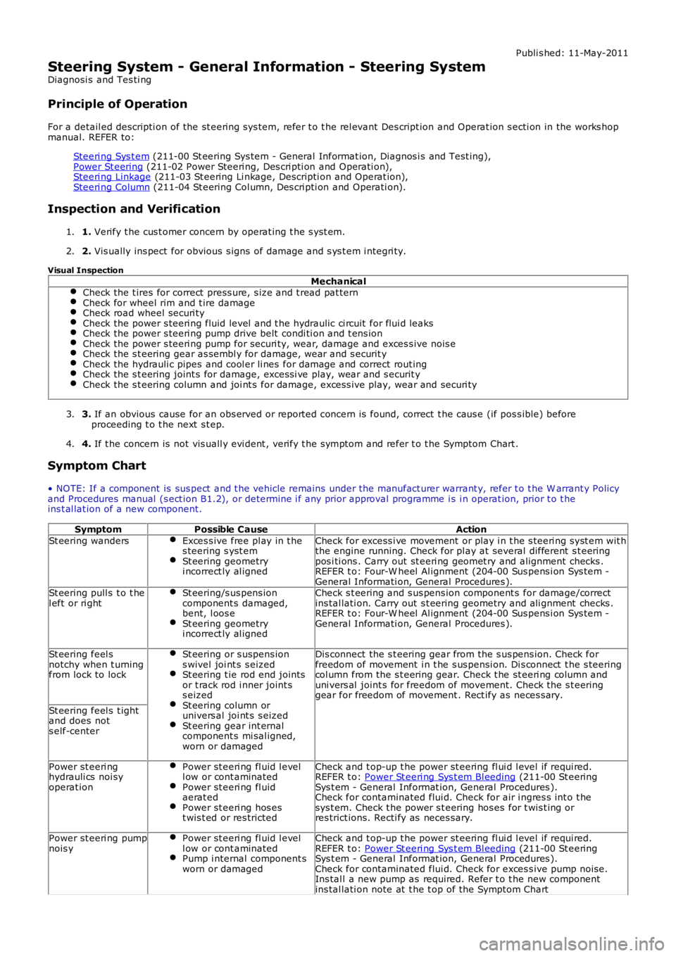
Steering System - General Information - Steering System
Diagnosi s and Tes ti ng
Principle of Operation
For a detail ed descripti on of the st eering sys tem, refer t o t he rel evant Des cript ion and Operat ion s ecti on in the works hopmanual. REFER to:
Steeri ng Sys t em (211-00 St eering Sys tem - General Informat ion, Diagnos i s and Test ing),Power St eering (211-02 Power Steeri ng, Des cri pti on and Operati on),Steeri ng Linkage (211-03 St eering Li nkage, Descripti on and Operat ion),Steeri ng Column (211-04 St eering Col umn, Des cri pti on and Operati on).
Inspection and Verification
1. Verify t he cus t omer concern by operat ing t he s yst em.1.
2. Vis ually ins pect for obvious s igns of damage and s ys t em i ntegri ty.2.
Visual Inspection
MechanicalCheck the t ires for correct press ure, s ize and t read pat ternCheck for wheel rim and t ire damageCheck road wheel securi tyCheck the power s teeri ng fluid level and t he hydraulic ci rcuit for flui d leaksCheck the power s teeri ng pump drive belt condi ti on and t ens ionCheck the power s teeri ng pump for securi ty, wear, damage and exces s ive nois eCheck the s t eering gear as sembl y for damage, wear and s ecurit yCheck the hydrauli c pipes and cool er li nes for damage and correct rout ingCheck the s t eering joint s for damage, excess i ve play, wear and s ecurit yCheck the s t eering column and joi nt s for damage, exces s ive play, wear and securi ty
3. If an obvious cause for an obs erved or report ed concern is found, correct t he caus e (if pos s ible) beforeproceeding t o t he next s t ep.3.
4. If t he concern is not vis uall y evi dent , verify t he s ymptom and refer t o t he Symptom Chart .4.
Symptom Chart
• NOTE: If a component is sus pect and t he vehicle remains under the manufact urer warrant y, refer t o t he W arrant y Policyand Procedures manual (s ect ion B1.2), or determine i f any prior approval programme is i n operat ion, prior t o t heins t al lat ion of a new component.
SymptomPossible CauseAction
St eering wandersExces s ive free pl ay in t hes teering s yst emSt eering geometryi ncorrect ly al igned
Check for excess i ve movement or play i n t he s teeri ng s yst em wit hthe engine running. Check for pl ay at several different s t eeringpos i ti ons . Carry out st eeri ng geomet ry and alignment checks .REFER t o: Four-W heel Al ignment (204-00 Sus pens i on Sys t em -General Informati on, General Procedures ).St eering pull s t o t hel eft or ri ghtSt eering/s us pens ioncomponent s damaged,bent, l oos eSt eering geometryi ncorrect ly al igned
Check s t eering and s us pens ion component s for damage/correctins tal lati on. Carry out s t eering geometry and ali gnment checks .REFER t o: Four-W heel Al ignment (204-00 Sus pens i on Sys t em -General Informati on, General Procedures ).
St eering feel snotchy when t urningfrom lock to lock
St eering or s uspens ions wivel joi nt s s eizedSt eering t ie rod end jointsor t rack rod i nner joint ss eizedSt eering column orunivers al joi nt s s eizedSt eering gear int ernalcomponent s mi sal igned,worn or damaged
Dis connect the s t eering gear from the s us pens ion. Check forfreedom of movement i n t he s us pensi on. Di s connect t he s teeringcol umn from the s t eering gear. Check t he st eeri ng col umn anduni vers al joint s for freedom of movement. Check the s t eeringgear for freedom of movement . Rect ify as neces s ary.
St eering feel s t ightand does nots elf-center
Power st eeri nghydrauli cs noi syoperat ion
Power st eeri ng fl uid l evell ow or cont aminatedPower st eeri ng fl uidaerat edPower st eeri ng hos est wis t ed or res tricted
Check and t op-up t he power st eering fl ui d l evel if requi red.REFER t o: Power St eeri ng Sys t em Bl eeding (211-00 St eeringSys t em - General Informat ion, General Procedures ).Check for contaminated flui d. Check for air i ngres s int o t hesys t em. Check t he power s t eering hos es for t wis t ing orres trict ions. Recti fy as neces sary.
Power st eeri ng pumpnois yPower st eeri ng fl uid l evell ow or cont aminatedPump i nternal component sworn or damaged
Check and t op-up t he power st eering fl ui d l evel if requi red.REFER t o: Power St eeri ng Sys t em Bl eeding (211-00 St eeringSys t em - General Informat ion, General Procedures ).Check for contaminated flui d. Check for exces s ive pump noi se.Ins tal l a new pump as required. Refer t o t he new componentins tal lati on note at t he t op of the Sympt om Chart