2006 LAND ROVER FRELANDER 2 lock
[x] Cancel search: lockPage 298 of 3229
Publi s hed: 11-May-2011
Ride and Handling Optimization - Ride and Handling Optimization
Diagnosi s and Tes ti ng
Principles of Operation
For a detail ed descripti on of the Terrain Respons e s ys t em, refer t o t he rel evant Descript ion and Operat ion secti on in theworks hop manual .REFER to: Ri de and Handl ing Opt imi zat ion (204-06 Ri de and Handl ing Opt imizati on, Des cript ion and Operat ion).
Inspection and Verification
CAUTION: Di agnos is by s ubs ti tut ion from a donor vehicle is NO T acceptabl e. Subs ti tut ion of cont rol modules doesnot guarant ee confirmat ion of a faul t, and may als o caus e addit ional fault s i n t he vehi cl e being t est ed and/or t he donorvehi cl e.
1. Verify t he cus t omer concern.1.
2. Vis ually ins pect for obvious s igns of mechani cal or electrical damage.2.
Visual InspectionMechanicalElectrical
* Ti re condit ion, pres sures, et cDriveline, Engine, Transmis s ion, Sus pensi on,component s (correct ins tall ati on, damage, etc)
Fus esHarness es /Connect orsTerrai n res pons e modul eEngi ne Cont rol Module (ECM)Transmis s ion Control Modul e (TCM)Ant i-Lock Brake Sys t em control modul eAct ive On-demand cont rol moduleDynami c s us pensi on cont rol module * Controllerarea network (CAN) ci rcuit s
3. If an obvious cause for an obs erved or report ed concern is found, correct t he caus e (if pos s ible) beforeproceeding t o t he next s t ep.3.
4. If t he caus e is not vis ually evi dent , check for Di agnos ti c Trouble Codes (DTCs) and refer t o t he DTC Index.4.
DTC Index
• NOTE: If the control modul e/t rans mis s ion i s s uspect and the vehicle remai ns under manufacturer warrant y, refer t o t heW arranty Pol icy and Procedures manual (s ect ion B1.2), or determine i f any pri or approval programme is in operat ion, pri ort o the ins tall ati on of a new module/transmis s ion.
• NOTE: Generic scan t ool s may not read the codes li st ed, or may read only fi ve digit codes . Mat ch the five di git s from t hes can tool to the firs t fi ve di git s of the seven digi t code l is ted to ident ify t he faul t (t he las t t wo digi ts gi ve addi ti onalinformat ion read by the manufact urer approved diagnos t ic s ys tem).
• NOTE: W hen performing el ect ri cal volt age or resi s tance tes t s, al ways us e a digit al mult imet er (DMM) accurate to threedeci mal places , and wi th an up-to-date cali brat ion cert ificate. W hen t es ti ng res is t ance, always take t he res i st ance of t heDMM leads int o account.
• NOTE: Check and recti fy bas ic faul ts before beginni ng diagnos t ic rout ines i nvol vi ng pinpoint t es t s.
• NOTE: Ins pect connect ors for s igns of water ingres s , and pins for damage and/or corros ion.
• NOTE: If DTCs are recorded and, aft er performi ng the pi npoi nt tes ts , a fault is not present , an int ermi tt ent concern maybe t he caus e. Always check for loose connect ions and corroded terminals .
For a compl ete lis t of all Di agnos ti c Trouble Codes (DTCs) t hat could be logged on this vehicle, pleas e refer to Sect ion100-00.
REFER to: Di agnos ti c Trouble Code (DTC) Index - DTC: Terrain Res pons e Cont rol Modul e (ATCM) (100-00 GeneralInformat ion, Des cript ion and Operat ion).
Page 321 of 3229
Not s ens it ive to brake tes ti ng on a chas si s dynamomet er.
Generati on 4 Acti ve On-Demand Coupli ng - Vehicles from 2009MY
The generati on 4 coupl ing does not have the di fferenti al s peed dri ven pump used on the previ ous generat ion 3coupl ing, but i s fit ted wi th a bigger capacit y electrically operated axial pump and a hi gh pres s ure accumul ator.The proport ional throt t le valve and press ure s ens or on t he generat ion 3 coupli ng is replaced wit h a proport ionalpres s ure reducing val ve.The t orque li mit er pres sure reducing valve on the generat ion 3 coupli ng is replaced by an electroni c cont rol valveand cont rol ling software.
The generati on 4 acti ve on-demand coupli ng gives t he fol lowing improvements over t he previous generati on 3 coupl ing:
Reduced bas e t orque at high different ial s peedsTorque acti vat ion i s now i ndependent of different ial s peedAccurat e t orque l imi ter cont rolEnergy s tored in hi gh pres s ure accumul ator givi ng a low maximum current consumpt ion of t he electric pump andfas t er res pons e.
Control Module - G eneration 3 and 4 Couplings
The cont rol module, at tached to the cas ing of t he act ive on-demand coupling, forms a s ingle unit wit h t he cont rolvalve/axial s ol enoi d. By anal yzi ng informat ion from other vehi cl e modules and s ensors t he cont rol module regul ates t heaxial sol enoi d t o cont rol t he hydraul ic flui d pres s ure s uppl ied t o t he clut ch pl ates. Some of t he modul es and s ens ors thecont rol module communi cat es wit h are li s ted below:
Hardwi red:- Control valve / axi al s olenoid- Electric hydrauli c pump- Oi l press ure and temperat ure sens orHigh speed CAN (cont rol ler area net work):- Engine cont rol module- Anti -l ock brake s ys t em / t racti on cont rol module- Tracti on res ponse swit ch- Y aw rate sens or- Steering wheel rot at ion sens or
The axial sol enoi d cons t ant ly adjust s t he cont rol valve output us ing a Pul se W i dt h Modulat ion (PW M) s i gnal. The flui dpres s ure deli vered t o t he cl utch plat es determines t he amount of t orque t hat is delivered t o t he rear axl e.
The act ive on-demand coupli ng has int egrated oi l press ure and temperature s ens ors to enable the control modul e t oaccurat ely manage t he t orque t ransfer under all environment al and operat ing condit ions . Usi ng thes e s ignals the controlmodule will us e s t rategi es to protect the coupli ng from overheati ng; in extreme cas es to protect t he coupli ng from damaget he coupli ng wil l dis engage i f the t emperat ure of t he hydraul ic flui d exceeds 105°C. The coupl ing wi ll ret urn to normalfuncti onal it y when t he temperat ure fall s below 101°C.
The cont rol module has an int egrated di agnos ti cs sys tem, whi ch cons tant ly moni tors the act ive on-demand couplings ys t em as wel l as it s input and output s ignals . If t he control modul e detects a fault a Diagnost ic Troubl e Code (DTC) i ss tored. The DTC is acces s ed usi ng t he Land Rover approved di agnos t ic s yst em.
Electric Hydraulic Pump
W hen negoti ati ng very low frict ion s urfaces s uch as wet gras s , snow or i ce; i nit ial wheel -s pin can cut i nt o t he s urface andreduce gri p. W it h a re-act ive on-demand coupl ing, almos t 60 degrees of wheel rotat ion woul d occur before torque could bet ransmit ted t hrough t he coupl ing.
On Generat ion 3 coupli ngs , t o count eract thi s Land Rover devel oped a uni que high-pres s ure pre-charge faci li ty whi chenergizes t he hydraul ic circui t as s oon as the engi ne is s t art ed. Es s ent ial ly an el ect ri cal ly operat ed hydraul ic pump wasdesi gned to maintai n a pot ent ial of 500 Nm (369 l b ft ) of t orque pres s ure wi thi n the coupli ng. (This pre-charge t orquecapacit y has been increas ed to 1500Nm (1106 l b ft ) for t he Generat ion 4 coupli ng.)
Vehicles fit ted wi th Terrai n Res pons e als o add furt her benefi ts by varying t he level of pre-charge t o deli ver opti mumt racti on over a range of di fferent t errai n s urfaces . The level of pre-charge is varied dependi ng on t he part icul ar terrainres ponse mode, for exampl e:
Terrai n respons e in 'Speci al Programs Off' mode as common wit h vehi cl es wit hout terrain res pons e, the coupli ng isprogrammed t o transmit 500 Nm 369 lb ft of t orque on Generat ion 3 couplings and 1500 Nm (1106 l b ft) of t orqueon Generat ion 4 couplings t o t he rear axle when the vehicle moves from res t i n a s t raight l ine. Thi s s trategymi ni mi zes t ract ion l os s from a s t andi ng-s tart regardles s of t he terrain. W hen the vehicle accelerat es the pres surein the coupling is decreas ed to improve fuel economy.The abili ty to sens e t he s teeri ng angl e all ows t he coupli ng t o be programmed t o provide no torque trans fer t hrought he coupli ng. This prevent s t he coupli ng locking when t he vehicle i s maneuvring at low s peeds and acute s teeri ngangl es.In 'Grass / Gravel / Snow' mode t he coupl ing i s programmed to maint ai n i ts pre-charge s t at e unt il much highers peeds are obtained. The s ame applies even i f the vehicle is t raveli ng at low speeds and acut e s t eering angles , ast racti on takes precedence over coupli ng lock-up on l ow-fri ct ion s urfaces .
For addit ional informat ion, refer t o: Ride and Handli ng Opti mizat ion (204-06 Ride and Handli ng Opt imi zat ion, Descripti onand Operat ion).
Mechanical Hydraulic Pump - Generation 3 Couplings - Vehicles up to 2009MY
The dri ves haft i s att ached t o t he coupl ing's front clut ch pl ate as s embly (i nput ), with the rear cl ut ch plat e as sembl yconnected t o t he different ial pini on (out put ). A s was h-pl ate wit h 6 hydrauli c rol lers is al so att ached t o t he different ialpinion. W hen there is no s peed difference bet ween the coupling's input and out put, the rol lers do not funct ion.
Page 322 of 3229
However, when the front and rear axl es st art t o rotat e at different s peeds , t he s wash-pl ate rot at es rel ati ve to the roll erswhich generat es the hydrauli c pres s ure. Thi s pres s ure i s us ed to force the opposi ng clut ch pl ates t oget her, i ncreas ing thet ransmis s ion of t orque t o the rear axl e. As the di fference in axl e s peed i ncreases the hydrauli c pres sure pushes t he clut chplat es further together t o increas e t he t orque to the rear axl e.
A control val ve/axi al s olenoid cont rols the amount of pres s ure appli ed to the clut ch plat es , and hence the amount oft orque transmit ted t o t he rear wheels . Clos e manufact uring t olerances and except ional ly low component wear ens uret orque cont rol remai ns accurat e t hroughout t he vehi cl e's l ife.
Mechanical Hydraulic Pump - Generation 4 Couplings - Vehicles from 2009MY
The Generati on 4 coupl ing does not us e the swas h pl at e t o mechanical ly rais e hydrauli c pres s ure; ins tead, a new hydraul icpump i s used to generat e hydrauli c pres sure and force the cl utch plat es toget her. The removal of t he s was h plat e all ows alarger overal l cl ut ch plat e s urface area, whi ch in t urn reduces t he hydrauli c pres sure requi rement. The press ure required toachi eve 1500Nm (1106 l b ft ) has been reduced from 100 Bar for Generat ion 3 coupli ngs to 40 Bar for Generati on 4coupl ings.
The posi ti oni ng of the Generat ion 4 coupl ing's i nput and output remains t he s ame as t he Generati on 3 coupl ing, asdescribed above.
By-pass Valve
On very low fricti on s urfaces, driveli ne drag t orque can occur, for exampl e:
revers e t orque from engi ne braking, orforced movement of t he dri ves haft by t he front wheel s .
This can i nfluence rear wheel s peed, maki ng it i mpos si ble t o determine the t rue fricti on capabil it y of the rear wheel s, bydis t orti ng t he wheel s peed s ignal. To prevent thi s, t he acti ve on-demand coupli ng is des i gned t o open i mmediat el y inres ponse to a s tabil it y cont rol event . This i s achi eved by a by-pass val ve ins tant ly reducing sys tem pres s ure t o nomi nal .
To balance the 4 bar bas e press ure (s ee below for detai ls ), t he Generati on 3 coupling us es a large Bel levill e s pri ng to forcet he cl utch plat es clear of each ot her t o prevent torque transmis si on t hrough the coupli ng. Even at 0°C, t orque t rans mis s ionis reduced from 300 Nm to Zero wi thi n 10 ms . The Generat ion 4 coupling however, does not require a Bel lvil le s pri ng t os eparate t he plat es as t he coupli ng does not have a si gni fi cant bas e pres s ure pus hi ng t he plates together.
Accumulator
The further t he cl utch pl at es have to move in order to contact each other, t he longer it t akes to di spl ace the hydrauli c fl uidneces s ary t o buil d pres s ure and t rans mit torque. To count er thi s, t he Generati on 3 coupling incorporates an accumulat or.This retains a nominal 4 bar pres sure wi thin the hydraul ic circui t. Al though thi s is not enough pres sure t o caus e s i gni fi cantt orque transmis s ion t hrough the coupli ng, i t forces t he plat es very clos e t oget her so that very l it tl e fluid di s pl acement i srequired t o achi eve full engagement and maxi mum t orque t rans fer. Ful l torque t rans miss i on can be achieved i n 150 ms .
On Generat ion 4 coupli ngs , t he 150ms act ivat ion t ime is achieved through the us e of a Bel lvil le s pri ng t hat acts to pus ht he plates t ogether (wi thout caus i ng si gnifi cant t orque t rans mis s ion t hrough t he coupl ing). As t he pump i s notcont inuousl y us ed to create t his bas e pres s ure (as i t was wit h Generat ion 3 coupli ng), improvement s i n fuel economy havebeen achi eved.
Wet Clutch Pack
The clutch pack is made up of 7 pairs of plat es ; t he inner dis cs are produced from hardened st eel wit h t he out er dis csmanufactured from s t eel wi th a s int ered face. The clutch pl ates operat e in trans mi s si on fl uid.
Torque t rans mis s ion acros s t he clutch pack is li mit ed t o 1500 Nm (1106 lb ft ). This ens ures t he l ower gears ret ai n anelement of front-wheel -drive for t ract ion s t abi lit y. W i thin the hi gher gears the coupl ing i s t heoreti call y capabl e oft ransmit ti ng all t he dri ve to the rear axle; al though condit ions woul d have to be ext reme for t his t o occur.
PRINCIPLES OF OPERATION
Generation 3 Couplings - up to 2009MY
An i nt ernal electroni cal ly-controll ed pump provides hydrauli c pre-charge pres sure wit hin the coupling. The pre-chargepres s ure s upplies t he requi red operat ing pres s ure to the clut ch plates to el imi nat e i nit ial wheel -s pin as the vehicleaccelerates from s tandst il l.
In conjunct ion wi th the pre-charge pres s ure a mechanical hydraul ic pump operates wi thi n the cl utch plat es to s upply thecoupl ing's mai n hydraulic operat ing pres sure. The mechanical pump is funct ioned by the 'i nput ' and 'output' of t he coupli ng:
input - dri ves haft connect ion from the front axle,output - different ial connecti on to the rear axl e.
Any s peed di fference bet ween t he front and rear axl es wil l st art t he operat ion of t he mechanical hydraul ic pump. Theamount of hydrauli c pres s ure appli ed to the cl ut ch pack by the pump det ermines the gap bet ween t he cl utch plat es. Forexampl e, the great er the hydraul ic pres s ure, t he s maller t he gap between t he plat es and s ubs equent ly t he great er thet orque transmit ted t hrough t he coupli ng from the front axle t o t he rear axle.
This mai n hydrauli c pres sure is des i gned t o t rans mit the t orque for tract ion demands of off-road drivi ng, and t o provi delock-up as requi red.
Generation 4 Couplings - from 2009MY
The Generati on 4 coupl ing s t il l us es an el ect ri cal ly-controlled pump to provide hydrauli c pre-charge to el imi nat e wheel-s pinfrom st ands t il l; however, the s ame pump is al s o used to provi de t he coupli ng's mai n hydraul ic operat ing press ure.
Page 357 of 3229
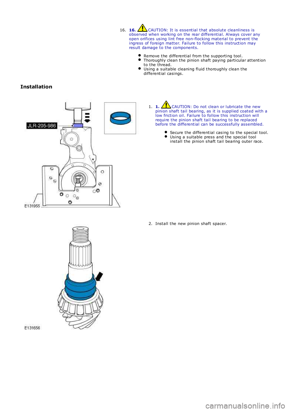
16. CAUTION: It is es s ent ial t hat abs olut e cleanl ines s isobs erved when working on the rear different ial. Al ways cover anyopen ori fi ces us ing lint free non-flocking mat eri al t o prevent t hei ngress of foreign matt er. Fail ure t o follow thi s ins truct ion mayres ult damage t o t he component s.
Remove t he different ial from t he s upporti ng tool .Thoroughl y clean t he pinion shaft paying parti cul ar at t ent iont o t he thread.Us ing a s ui table cl eani ng fl uid t horoughly clean t hedifferent ial casi ngs .
16.
Installation
1. CAUTION: Do not clean or l ubricate the newpini on s haft tai l bearing, as it i s s uppl ied coat ed wi th al ow frict ion oil . Fai lure t o fol low t his ins truct ion wi llrequi re t he pini on s haft tai l bearing t o be repl acedbefore t he different ial can be succes s ful ly as s embled.
Secure t he different ial cas i ng to the s peci al tool.Us ing a s ui table pres s and t he special t ooli ns t all the pi nion s haft t ail bearing out er race.
1.
Inst all t he new pini on shaft spacer.2.
Page 359 of 3229
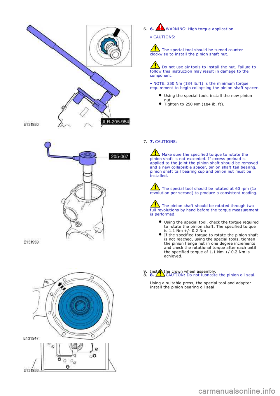
6. W ARNING: High t orque applicat ion.
• CAUTIONS:
The s peci al tool s hould be t urned count erclockwis e t o ins t al l the pi nion s haft nut.
Do not us e ai r tools to i nst all t he nut. Fail ure t ofol low thi s ins truct ion may res ult i n damage t o thecomponent .
• NOTE: 250 Nm (184 lb.ft) i s t he mi ni mum torquerequi rement to begi n collaps ing t he pini on s haft s pacer.
Us ing t he s peci al t ools i nst all t he new pini onnut.Tight en to 250 Nm (184 ib. ft).
6.
7. CAUTIONS:
Make s ure the specified t orque t o rot ate thepini on s haft is not exceeded. If exces s prel oad isapplied to the joint t he pinion s haft s hould be removedand a new col lapsi ble s pacer, pinion shaft tail beari ng,pini on s haft tai l bearing cup and pinion nut mus t bei ns t alled.
The s peci al tool s hould be rot ated at 60 rpm (1xrevolut ion per s econd) t o produce a cons i st ent reading.
The pi ni on s haft s houl d be rotat ed through t woful l revolut ions by hand before the t orque meas urementi s performed.
Us ing t he s peci al t ool, check t he t orque requiredt o rot ate the pi nion s haft . The specified t orquei s 1.1 Nm +/- 0.2 NmIf the s pecifi ed t orque t o rot ate the pi ni on s hafti s not reached, usi ng t he s pecial t ool s, t ight ent he pinion flange nut in one degree increment sand check t he rot ati onal t orque after each unt ilt he s pecified t orque of 1.1 Nm +/-0.2 Nm i sachi eved.
7.
8. CAUTION: Do not l ubricate the pi ni on oil s eal.
Us ing a s ui table pres s, t he s peci al t ool and adapt eri ns t all the pi nion beari ng oil s eal .
8.Inst all t he crown wheel ass embly.9.
Page 408 of 3229
The parking brake is a manual ly appli ed cabl e s ys t em t hat operates brake s hoes, housed wit hin the i nner diamet er of eachrear brake di sc.
FRONT AND REAR DISC BRAKES
The 3.2L i 6 vehicle i s ins t al led wit h vent il ated front and rear brake di scs . The 2.2L TD4 vehicle is i nst all ed wit h venti latedfront and sol id rear brake dis cs. Bot h t he i6 and TD4 vehicl es feature s ingle pi s ton, s lidi ng cal ipers on all brake dis cs . Foraddi ti onal i nformat ion, refer to:
Front Dis c Brake (206-03 Front Di sc Brake, Des cri pt ion and Operati on),Rear Di sc Brake (206-04 Rear Di s c Brake, Des cri pti on and Operati on).
PARKING BRAKE
The parking brake is a manual ly appli ed, cable operat ed s yst em. The RH and LH rear brake dis cs form the parki ng brakedrums , and provide the l ocat ion for the parki ng brake s hoes and components .For addit ional informat ion, refer t o: Parking Brake (206-05 Parki ng Brake and Act uat ion, Descripti on and Operat ion).
HYDRAULIC BRAKE ACTUATION
Hydrauli c brake act uati on cons is t s of the brake pedal , mast er cyl inder, HCU, and t he connect ing hydraul ic pipes and hos es.
The t andem brake mas ter cylinder wit h reservoi r is at tached to, and operat ed by t he brake boos t er. The brake mas t ercyl inder is a tandem des ign t hat suppli es pres s ure t o 2 i ndependent (pri mary and secondary) hydraul ic circui ts .For addit ional informat ion, refer t o: Hydraulic Brake Actuati on (206-06 Hydraulic Brake Act uati on, Des cri pt ion andOperat ion).
BRAKE BOOSTER
The brake boost er is vacuum operat ed and provides power as s is t ance t o t he brake hydrauli c s ys t em. The boos t er i s oft andem des ign that incorporat es 2 s eparate diaphragms . On both the gas oline and di esel models , t he vacuum required forboos t er operat ion is produced by an engine driven, vacuum pump.For addit ional informat ion, refer t o: Brake Boos ter (206-07 Power Brake Act uati on, Des cript ion and Operat ion).
ANTI-LOCK CONTROL
The anti -l ock control sys tem feat ures a Cont inental Teves Mk25E1 ABS module wit h i ntegral 4 channel HCU. The ABSmodule and HCU provide brake sys tem monit ori ng, and acti ve brake funct ions t o cont rol t he vehi cl e s tabil it y and t racti on.The ABS module al s o provides s peci fi c functi ons to as s is t t he vehi cl e duri ng off-road drivi ng.
The anti -l ock control sys tem provides t he fol lowing funct ions :
Anti -l ock Brake Sys t em (ABS)Corner Brake Control (CBC)Dynamic St abi li ty Cont rol (DSC)Electroni c Brake Force Di s tributi on (EBD)Electroni c Tracti on Control (ETC)Emergency Brake As s is t (EBA)Engi ne Drag-Torque Control (EDC)Hil l Descent Cont rol (HDC) wit h gradi ent release cont rolRoll Stabi lit y Control (RSC)Terrai n Res pons e™ sys tem int egrati on.
For addit ional informat ion, refer t o: Anti -Lock Cont rol - St abi li ty As s is t (206-09C Anti -Lock Cont rol - St abi lit y As s is t,Des cript ion and Operat ion).
Page 414 of 3229
1
1
1
1
1
1
1
2
Is t he power brake boost er val ve OK?YesCHECK the brake boos t er. For addit ional informat ion, refer t o Brake Boos t er component t es t in t hissect ion. INSTALL a new brake boos ter as requi red.REFER t o: Brake Boos ter (206-07 Power Brake Act uati on, Removal and Ins tal lati on).TEST the s ys tem for normal operat ion.NoINSTALL a new brake boos t er valve. TEST the sys tem for normal operat ion.
PINPOINT TEST H : BRAKE LOCKUP DU RING LIG HT BRAKE PEDAL FORCE
T EST CONDIT IONSDET AILS/RESULT S/ACT IONS
H1: T EST BRAKE LOCKUPRoad t est t he vehicle and apply the brake pedal li ght ly.
Do t he brakes l ockup?YesGO to H2.NoVehicle is OK.
H2: INSPECT BRAKE PADS
Inspect brake pads for contami nat ion, correct ins t al lat ion, damage and type.
Are any concerns found?YesINSTALL t he brake pads correct ly or INSTALL new brake pads as required.REFER t o: Brake Pads (206-03 Front Di s c Brake, Removal and Ins t allat ion) /Brake Pads (206-04 Rear Dis c Brake, Removal and Inst all ati on).TEST t he s ys t em for correct operati on.NoGO to H3.
H3: INSPECT BRAKE CALIPERSInspect brake calipers for bindi ng, l eaking or s t icking.
Are any concerns found?YesINSTALL t he brake cali pers correct ly or INSTALL new brake cal ipers as required.REFER t o: Brake Caliper (206-03 Front Dis c Brake, Removal and Ins tall ati on) /Brake Cal iper (206-04 Rear Di sc Brake, Removal and Ins t al lat ion).TEST t he s ys t em for normal operati on.NoVehicle is OK.
PINPOINT TEST I : BRAKES DRAG
T ESTCONDIT IONSDET AILS/RESULT S/ACT IONS
I1: ROAD T EST VEHICLE
Road t es t t he vehi cl e and apply t he brakes .
Are the brakes funct ioning correct ly?YesVehicle i s OK.NoGO to I2.
I2: CHECK BRAKE CALIPERS AND PARKING BRAKE CABLES
Check the front and rear cali per pis t ons and pins for bi ndi ng, l eaki ng or st icking and parki ng brakecabl es for s t icki ng/binding.
Do t he dis c brake cali per pi st ons and pins bind, l eak or s t ick, or t he parking brake cabl es st ick/bi nd?YesREPAIR or INSTALL new components as required. Tes t the s ys tem for normal operat ion. Road tes tvehi cle i f neces sary.NoGO to I3.
I3: CHECK BRAKE BO OST ER
Check the brake boos ter connecti ng rod alignment and t ravel.
Is the connect ing rod OK?YesVehicle i s OK.NoINSTALL a new brake boost er.REFER to: Brake Boos t er (206-07 Power Brake Actuat ion, Removal and Ins t allat ion).TEST the sys tem for normal operat ion.
PINPOINT TEST J : EXCESSIVE/ERRATIC BRAKE PEDAL TRAVEL
T ESTCONDIT IONSDET AILS/RESULT S/ACT IONS
J1: T EST ON ROUGH ROAD
Road t es t the vehicle on rough road condit ions .
Apply the brakes s l owly.
Is t he brake pedal effort and brake pedal t ravel normal?YesVehicl e is OK.NoGO t o J2.
J2: CHECK BRAKE FLUID LEVEL
Page 416 of 3229
brake boos ter.
5. Operate the engine for a minimum of 10 s econds at a fast i dle. Stop the engine and al low t he vehicle t o s t andfor 10 mi nut es. Then, appl y the brake pedal wi th approxi mately 89 N (20lb) of force. The pedal feel (brakeappli cat ion) s houl d be t he s ame as t hat not ed wit h t he engine runni ng. If the brake pedal feel s hard (no poweras s is t), ins t al l a new valve and t hen repeat t he tes t. If t he brake pedal s t ill feels hard, i ns t all a new brakeboos ter. If t he brake pedal movement feel s s pongy, bleed t he brake s ys t em.REFER t o: Brake Syst em Bl eedi ng (206-00 Brake Syst em - General Informati on, General Procedures ) /Brake Sys t em Pres s ure Bl eedi ng (206-00 Brake Syst em - General Informati on, General Procedures ).
5.
Brake Master Cylinder
Us ual ly, t he fi rs t and s tronges t indicat or of anything wrong i n t he brake s ys t em i s a feeling through t he brake pedal. Indiagnosi ng the condit ion of t he brake mas t er cyli nder, check pedal feel as evidence of a brake concern. Check for brakewarni ng lamp ill uminat ion and t he brake fluid level i n t he brake mas t er cyli nder reservoi r.
Normal Condit ions
The fol lowing condit ions are cons idered normal and are not i ndi cat ions t hat t he brake mast er cyl inder i s i n need of repair.
Modern brake sys tems are des igned t o produce a pedal effort that is not as hard as in the pas t . Compl aint s of lightpedal effort s s houl d be compared t o t he pedal efforts of another vehi cl e of t he s ame model and year.The fl uid l evel wi ll fal l wit h brake pad wear.
Abnormal Condi ti ons
Changes i n t he brake pedal feel or brake pedal travel are indicators t hat s omet hi ng coul d be wrong in the brake sys tem.The diagnost ic procedure and techni ques us e brake pedal feel , warning i ndi cat or il lumi nat ion and l ow brake flui d level asindicat ors t o diagnosi ng brake s yst em concerns . The foll owing condi ti ons are consi dered abnormal and indi cat e t hat t hebrake mas t er cyli nder i s in need of repai r:
• NOTE: Pri or to carrying out any diagnosi s , ens ure the brake sys tem warni ng indicator i s functi onal .
Brake pedal goes down fast . This could be caus ed by an external or int ernal leak.Brake pedal goes down s l owl y. Thi s coul d be caused by an int ernal or external l eak.Brake pedal is l ow or feels spongy. Thi s condit ion may be caus ed by no fl ui d i n the brake mas ter cylinder, reservoi rcap vent holes cl ogged or air i n t he hydraul ic s ys tem.Brake pedal effort is excess ive. This may be caus ed by a bi nd or obs t ructi on in the pedal/li nkage, a faul tynon-ret urn val ve, boost er or ins ufficient boos t er vacuum.Rear brakes lock up during light pedal force. Thi s may be caus ed by damaged brake pads , a parti ally appl ied parkingbrake, a damaged ABS s ens or or bearing fail ure.Brake pedal effort errat ic. This condit ion could be caus ed by the brake boos t er or incorrectl y ins tal led brake pads .Brake warning i ndi cat or is on. This may be caus ed by low fl uid l evel or fl oat as s embly damaged.
Non Pressure Leaks
Any reduced fl uid volume in t he brake mast er cyl inder res ervoi r may be caused by two types of none pres sure externalleaks .
Type 1: An ext ernal leak may occur at the brake mast er cyl inder res ervoir cap because of incorrect posi ti oning of t hegasket and cap. Repos it ion cap and gasket .
Type 2: An ext ernal leak may occur at the brake mast er cyl inder res ervoir mounti ng seal s. Repair s uch a l eak by ins tall ingnew s eals and make s ure that t he brake mas t er cyli nder reservoi r ret ai ning bolt i s correct ly i nst all ed.