2006 LAND ROVER FRELANDER 2 lock
[x] Cancel search: lockPage 530 of 3229
Publi s hed: 11-May-2011
Steering System - General Information - Power Steering System Bleeding
General Procedures
Clean power s teering fluid res ervoir around t he fi ll er cap and flui di ndi cat or.1.
Check the power s teeri ng fluid, if aerat ed, wait unti l fl ui d i s freefrom bubbles then t op-up res ervoi r to UPPER l evel mark wit hrecommended fluid.
2.
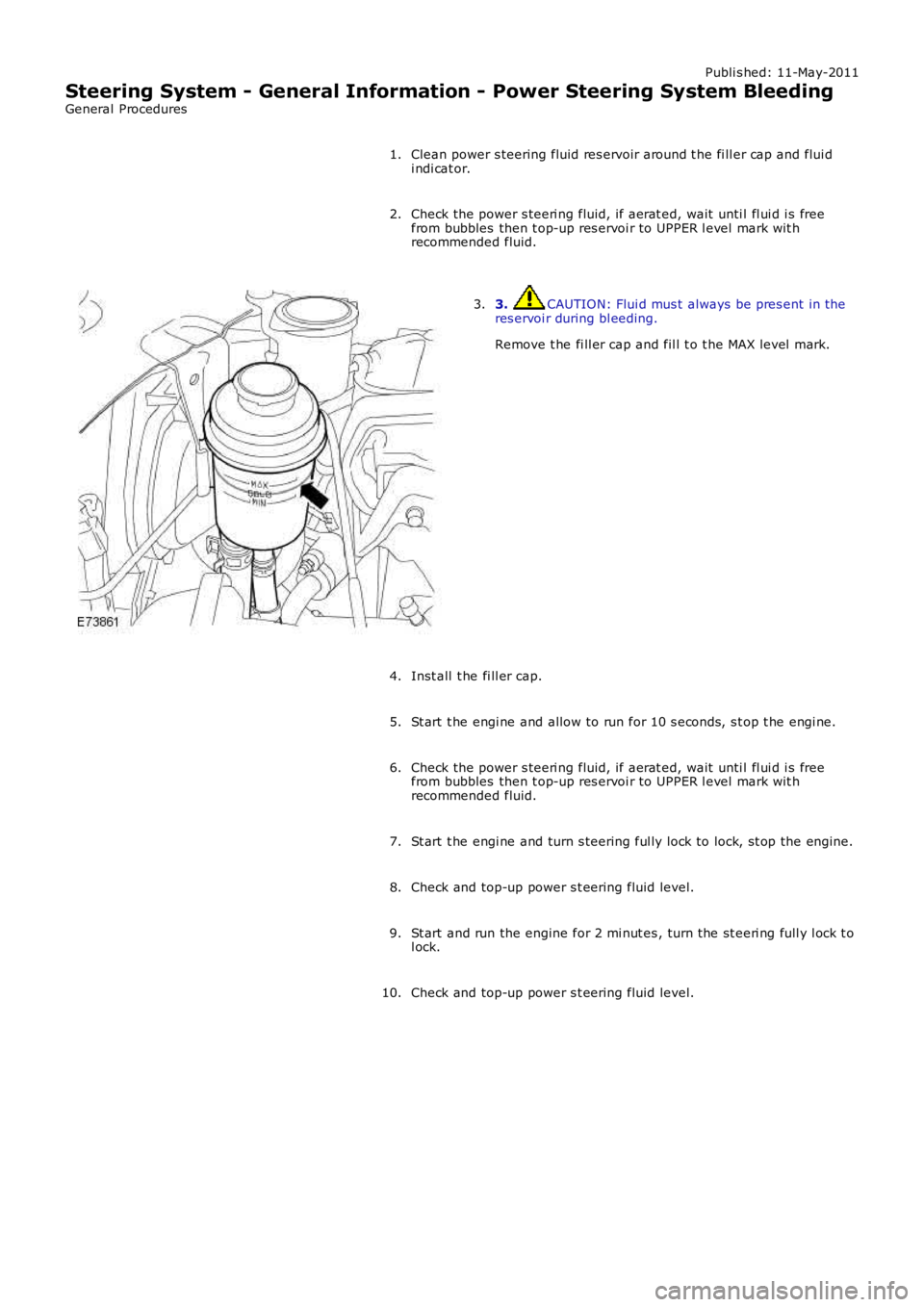
3. CAUTION: Flui d mus t always be pres ent in theres ervoi r during bl eeding.
Remove t he fi ll er cap and fil l t o t he MAX level mark.
3.
Inst all t he fi ll er cap.4.
St art t he engi ne and allow to run for 10 s econds, s t op t he engi ne.5.
Check the power s teeri ng fluid, if aerat ed, wait unti l fl ui d i s freefrom bubbles then t op-up res ervoi r to UPPER l evel mark wit hrecommended fluid.
6.
St art t he engi ne and turn s teering ful ly lock to lock, s t op the engine.7.
Check and top-up power s t eering fluid level.8.
St art and run the engine for 2 mi nut es , turn the st eeri ng full y l ock t ol ock.9.
Check and top-up power s t eering fluid level.10.
Page 533 of 3229
9. CAUTIONS:
Be prepared t o collect es caping flui ds .
Do not al low the power s teeri ng fl uid l evel i n t he powers teering fluid res ervoir t o fal l bel ow t he mi ni mum powers teering fluid level. Failure t o fol low this ins truct ion may res ulti n damage to the power s teering s yst em.
Make s ure the engine is s wi tched off as s oon as t he ful l4 l it res of power s teeri ng fl uid has ent ered t he power s t eeringfluid res ervoir.
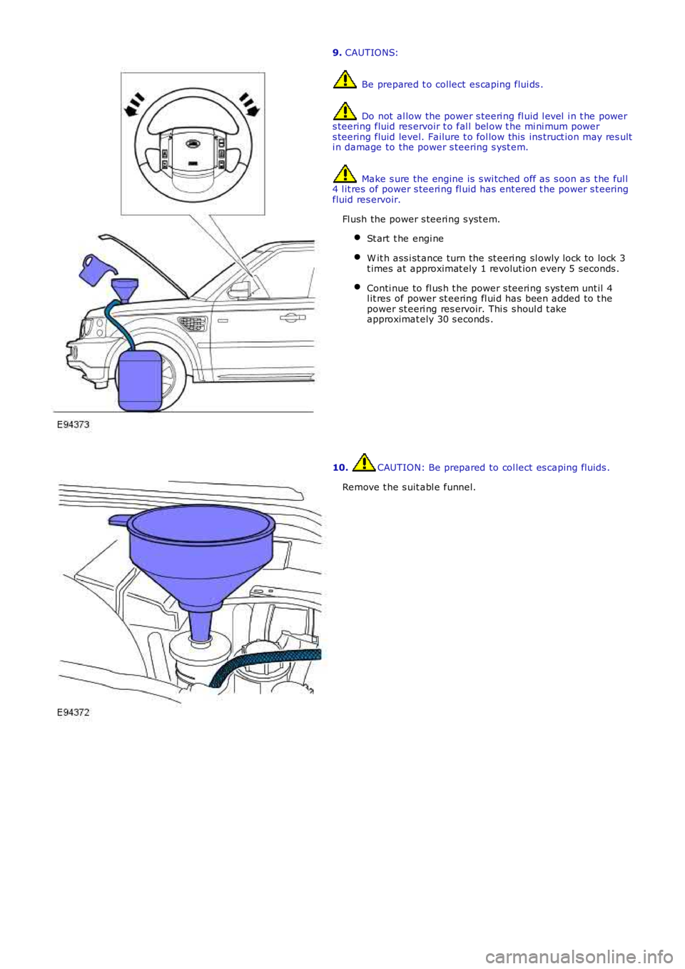
Fl ush the power s teeri ng s yst em.
St art t he engi ne
W it h ass i st ance turn the st eeri ng sl owly l ock to lock 3t imes at approximat ely 1 revolut ion every 5 seconds .
Conti nue to fl us h t he power s teeri ng s ys t em unt il 4l it res of power st eering fl ui d has been added to t hepower st eeri ng res ervoir. Thi s s houl d t akeapproximat ely 30 s econds .
10. CAUTION: Be prepared to col lect es caping fluids .
Remove t he s uit abl e funnel.
Page 538 of 3229
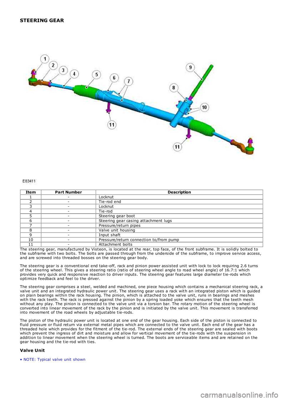
STEERING GEAR
ItemPart NumberDescription
1-Locknut2-Tie-rod end
3-Locknut
4-Tie-rod5-Steering gear boot
6-Steering gear cas ing at t achment lugs
7-Pres s ure/return pipes8-Valve unit hous ing
9-Input s haft
10-Pres s ure/return connecti on to/from pump11-At tachment bol ts
The s teeri ng gear, manufactured by Vis t eon, i s located at t he rear, top face, of t he front subframe. It is s oli dl y bolt ed t ot he subframe wit h t wo bolt s. The bolt s are pass ed t hrough from the unders ide of t he s ubframe, t o i mprove s ervi ce access ,and are screwed into threaded bos s es on the st eering gear body.
The s teeri ng gear is a convent ional end take-off, rack and pi ni on power as s is t ed unit wi th l ock to lock requiring 2.6 turnsof the st eering wheel . Thi s gives a s t eering rati o (rat io of s t eering wheel angl e t o road wheel angl e) of 16.7:1 whi chprovides very qui ck and res pons ive react ion t o driver inputs . The s teeri ng gear features large di ameter t ie-rods whichopti mize feedback and feel t o t he driver.
The s teeri ng gear compris es a s t eel , welded and machined, one pi ece hous ing whi ch cont ai ns a mechanical s t eering rack, avalve unit and an i ntegrat ed hydraulic power unit . The s teeri ng gear us es a rack with an i nt egrat ed pis ton whi ch is gui dedon plai n bearings wi thi n t he rack hous i ng. The pi ni on, whi ch is at tached t o the val ve uni t, runs in bearings and mes heswit h t he rack t eeth. The rack i s pres s ed agai nst t he pini on by a s pri ng loaded yoke which ensures that t he teet h mes hwit hout any pl ay. The pi ni on is connect ed t o t he val ve unit via a tors ion bar. The rotary moti on of the st eeri ng wheel i sconvert ed i nt o l inear movement of t he rack by t he pinion and is i nit iated by the valve uni t. This movement i s transferredint o movement of the road wheel s by adjus t abl e t ie-rods.
The pis t on of the hydrauli c power uni t is l ocat ed at one end of the gear hous ing. Each s ide of t he pis ton i s connected tofl uid press ure or fl ui d ret urn vi a external met al pipes which are connected t o t he valve unit . Each end of t he gear has at hreaded hol e which provi des for the fi tment of t he ti e-rod. The external ends of t he st eeri ng gear are s eal ed wit h bootswhich prevent t he ingres s of dirt and mois t ure and al low for verti cal movement of the t ie-rods wi th the s us pens ion inaddi ti on t o li near movement when t he s teeri ng wheel i s t urned. The boot s are s ervi ceable it ems and are ret ai ned on t hegear hous ing and t he t ie-rod wi th ti es .
Valve Unit
• NOTE: Typi cal valve unit shown
Page 541 of 3229
3-Pres s ure out put port (t o s t eering gear val ve unit )
The pump i s a fixed dis placement, vane type pump which s uppl ies hydrauli c pres sure to t he st eeri ng gear valve unit . Thepump i s located at t he rear of t he engi ne and is driven by t he Rear Engi ne Auxi liary Drive (READ) Poly Vee bel t which i sindirect ly driven from t he cams haft s . The pump s uppl ies a cons tant fl ow rate, t herefore the out put i s i ndependent ofpump/engine s peed. A s el f-adjus ti ng tens ioner is fit t ed to maint ai n t he correct t ension on the bel t.
The pump contains a number of vanes which rot ate wit hin a cam ri ng and are driven by t he i nput s haft . As the vanesrot ate, t he cam ring causes t he s pace bet ween the vanes t o increas e. Thi s caus es a depres s ion bet ween the vanes andfl uid i s drawn from t he res ervoir vi a t he suct ion hos e int o t he s pace between the vanes. As t he s haft rotat es , t he inl etport i s clos ed to the vanes which have drawn in fluid, t rapping t he fluid bet ween t he vanes . The cam ring caus es t he s pacebetween t he vanes to reduce and cons equenti ally compress es and pres s uri zes t he hydrauli c fl ui d t rapped between t hem.Furt her rotat ion of t he s haft moves the vanes t o the out let port . As t he vanes pas s t he port plat e t he pres surized fluidpass es from the pump out let port into the press ure hose to the s t eering gear.
The pres s urized fluid is s ubject t o cont rol by a flow cont rol and pres s ure relief valve. The fl ow control valve maintai ns acons t ant flow of flui d s uppl ied t o t he s teeri ng gear irres pecti ve of engi ne s peed variati ons . The pres s ure reli ef val ve limit st he maximum pres sure on t he output s ide of t he pump. A met eri ng orifice i s included i n t he dis charge port of the pump.
If the pres s ure in t he ori fi ce reaches a predetermined l evel , a s pring loaded bal l in t he cent re of the flow cont rol valve isli ft ed from it s s eat and al lows pres s uri zed flui d t o recircul ate wit hi n t he pump. The pres sure rel ief valve wi ll operate if t hedis charge from the pump is rest ri ct ed, for example, s teeri ng held on full l ock. If the output from the pump is bl ocked, al loutput is recirculat ed t hrough the pump. In t his condi ti on, as no fresh fl ui d i s drawn i nto the pump from t he res ervoir, thefl uid t emperat ure i nsi de t he pump wil l increas e rapi dl y. Cons equent iall y, periods of operati on of the s t eering gear on ful llock s houl d be kept to a mi nimum to prevent overheati ng of the pump and the flui d within it .
The pump has an i nternal pres s ure reli ef valve whi ch als o i ncorporat es a flow cont rol val ve. The press ure rel ief val ve li mit s
t he maximum pres sure s uppl ied t o t he s teering gear to 125 bar (1812 lbf in2) ± 4 bar (58 l bf in2). The flow control val ve
li mit s t he maximum flow t o 8.8 l/mi n (1.93 gal/min) ± 0.5 l/min (0.1 gal/min) at 10 bar (145 bf i n2) The pump has a
dis placement of 11 cc/rev (0.67 i n3/rev).
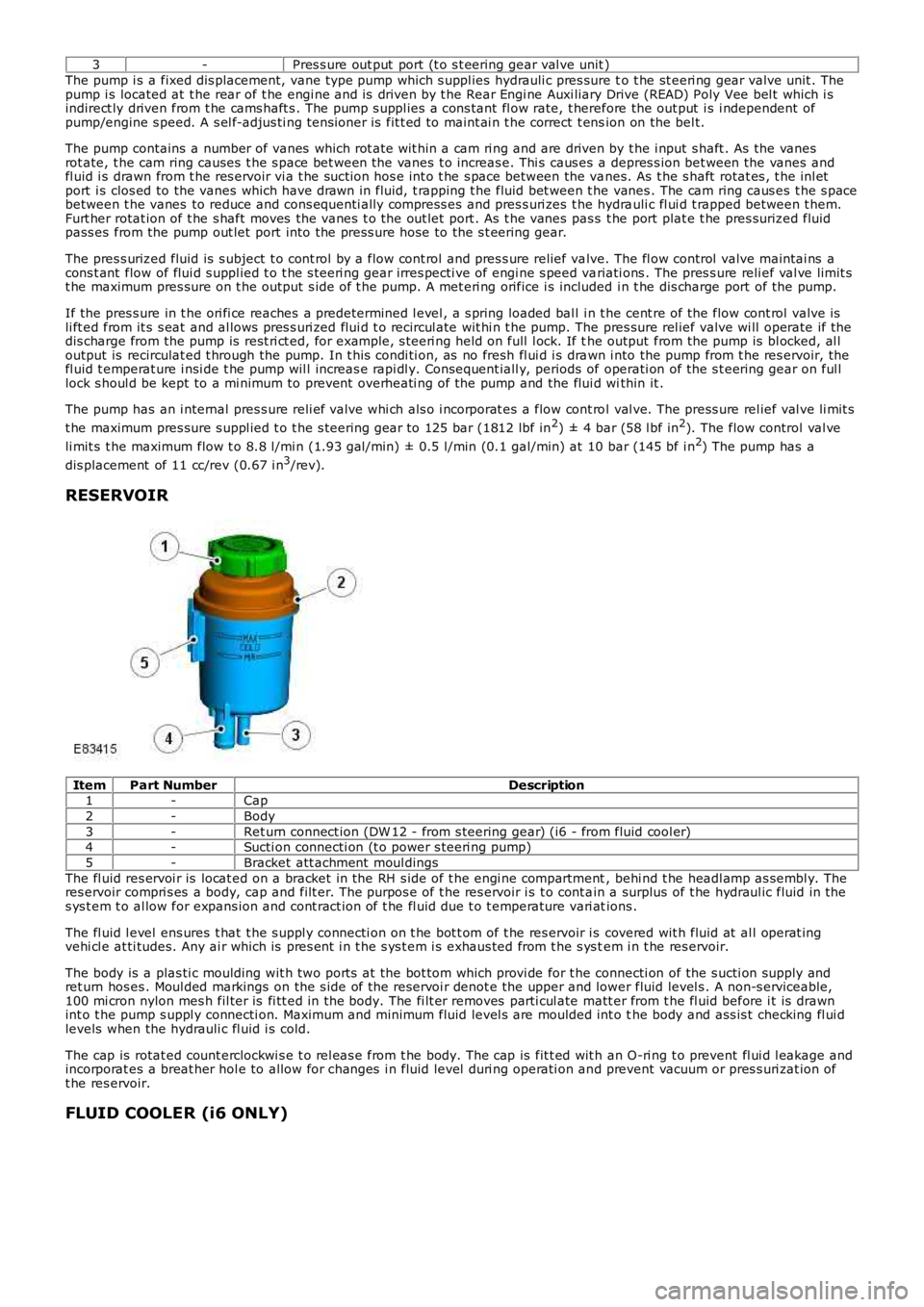
RESERVOIR
ItemPart NumberDescription1-Cap
2-Body
3-Ret urn connect ion (DW 12 - from s teering gear) (i6 - from fluid cool er)4-Sucti on connecti on (t o power s teeri ng pump)
5-Bracket att achment moul dings
The fl uid res ervoi r is locat ed on a bracket in the RH s ide of t he engi ne compartment, behi nd t he headl amp as sembl y. Theres ervoir compri s es a body, cap and filt er. The purpos e of t he res ervoir i s t o cont ain a surplus of t he hydraul ic fluid in thes ys t em t o al low for expans ion and cont ract ion of t he fl uid due t o t emperature vari ations .
The fl uid l evel ens ures t hat t he s uppl y connecti on on t he bot t om of t he res ervoir i s covered wit h fluid at al l operat ingvehi cl e at ti tudes. Any ai r which is pres ent i n t he s ys t em i s exhaus ted from t he s ys tem i n t he res ervoir.
The body is a plas ti c moulding wit h two port s at the bot tom which provi de for t he connecti on of the s ucti on supply andret urn hos es . Moul ded markings on the s ide of t he reservoi r denot e the upper and lower fluid level s . A non-s erviceable,100 mi cron nylon mes h fil ter is fi tt ed in the body. The fi lt er removes parti cul ate matt er from t he fl uid before i t is drawnint o t he pump s uppl y connecti on. Maximum and minimum fluid level s are moulded int o the body and ass is t checking fl ui dlevels when the hydrauli c fl uid i s cold.
The cap is rotat ed count erclockwi s e t o rel eas e from t he body. The cap is fit t ed wit h an O-ri ng t o prevent fl ui d l eakage andincorporat es a breat her hol e to allow for changes i n fluid level duri ng operati on and prevent vacuum or pres s uri zat ion oft he res ervoir.
FLUID COOLER (i6 ONLY)
Page 547 of 3229
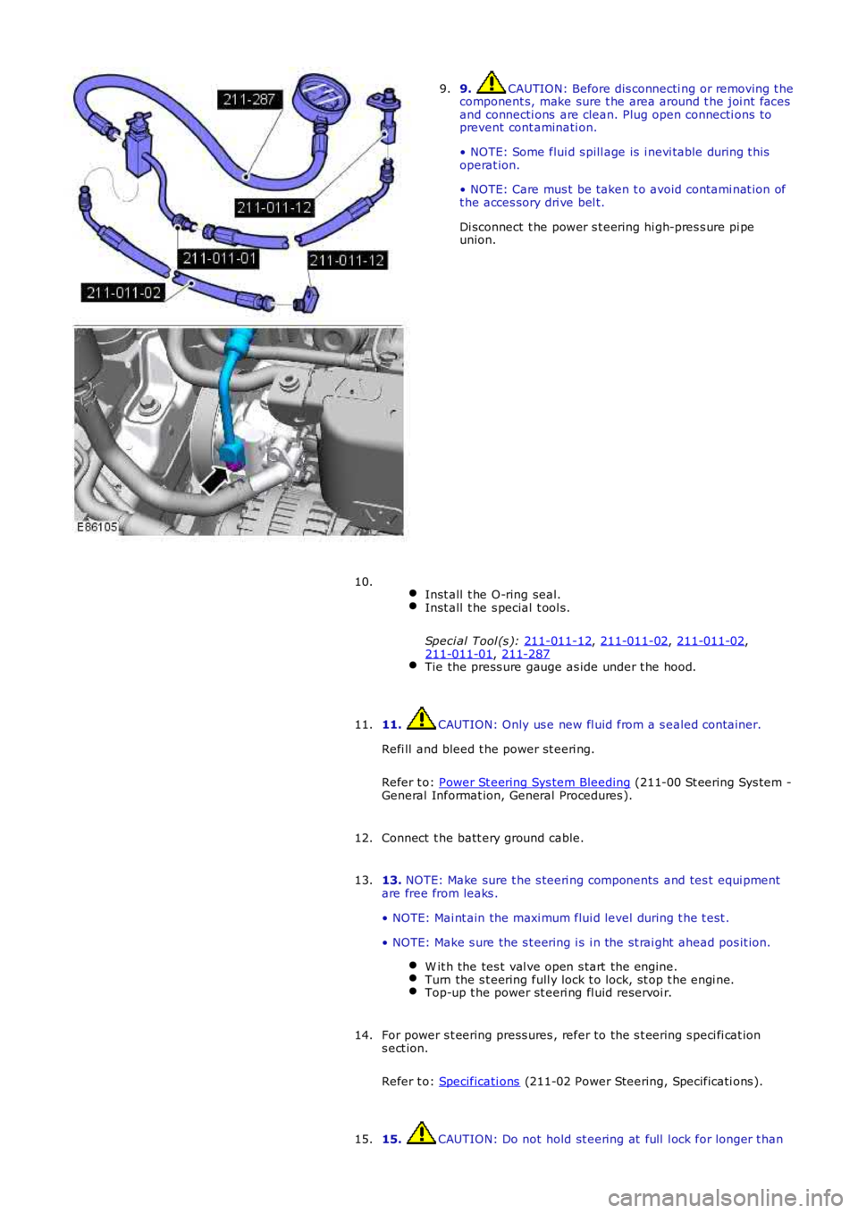
9. CAUTION: Before dis connecti ng or removing t he
component s, make sure t he area around t he joi nt faces
and connecti ons are clean. Plug open connecti ons to
prevent cont aminati on.
• NOTE: Some flui d s pill age is i nevi table during t his
operat ion.
• NOTE: Care mus t be taken t o avoid contami nat ion of
t he acces sory dri ve bel t.
Di sconnect t he power s t eering hi gh-pres s ure pi pe
union.
9.
Inst all t he O-ring seal. Inst all t he s pecial t ool s.
Speci al Tool (s ): 211-011-12 ,
211-011-02 ,
211-011-02 ,
211-011-01 ,
211-287 Tie the press ure gauge as ide under t he hood.10.
11. CAUTION: Only us e new fl uid from a s ealed container.
Refi ll and bleed t he power st eeri ng.
Refer t o: Power St eering Sys tem Bleeding (211-00 St eering Sys tem -
General Informat ion, General Procedures ).
11.
Connect t he batt ery ground cable.
12.
13. NOTE: Make sure t he s teeri ng components and tes t equi pment
are free from leaks .
• NOTE: Mai nt ain the maxi mum flui d level during t he t est .
• NOTE: Make s ure the s t eering i s i n the st rai ght ahead pos it ion. W it h the tes t val ve open s tart the engine. Turn the s t eering full y lock t o lock, st op t he engi ne.
Top-up t he power st eeri ng fl uid reservoi r.13.
For power s t eering press ures , refer to the s t eering s peci fi cat ion
s ect ion.
Refer t o: Specificati ons (211-02 Power Steering, Specificati ons ).
14.
15. CAUTION: Do not hold st eering at full l ock for longer t han
15.
Page 552 of 3229
Turn the s t eering full y lock-t o-l ock, s top t he engine.
Top-up t he power st eeri ng fl uid reservoi r.
For power s t eering press ures , refer to the s t eering s peci fi cat ion
s ect ion.
Refer t o: Specificati ons (211-02 Power Steering, Specificati ons ).
10.
11. CAUTION: Do not hold st eering at full l ock for longer t han
10 s econds .
W it h the engi ne at idle, s lowl y turn t he s teeri ng wheel and
hold on full l ock. Record t he pres s ure readi ng.11.
Repeat t he above procedure for t he other s ide. Record t he pres s ure readi ng.12.
W it h the engi ne at idle, rel ease the s t eering wheel. The press ure
s houl d be, at or bel ow, the pres s ure specified.
13.
Pres s ure out si de t hi s t olerance, i ndicat es a fault .
14.
15. CAUTION: Pump damage wi ll occur if t he t est valve is
clos ed for l onger peri ods .
To det ermi ne if t he fault is i n t he st eeri ng pump or the st eeri ng
rack, clos e the tes t val ve for a maxi mum of 5 s econds.
15.
If the press ures recorded fal l out s ide t he given values, replace the
power st eeri ng pump.
16.
If the maxi mum pump pres sure i s correct, t hen s uspect the power
s teering rack.
17.
18. CAUTION: Dis card flui d s iphoned from t he power st eeri ng
s yst em.
On compl et ion of t he t est s t op the engi ne, dis connect t he bat t ery
ground cable and s i phon t he fluid from t he power st eering res ervoir.
18.
Di sas s emble t he t es t equipment .
19.
Clean t he component mat ing faces . Inst all a new O-ring s eal.
Connect t he high-press ure pipe union t o t he power st eeri ng
pump. T orque:
25 Nm 20.
Inst all t he air cleaner hous ing.
Refer t o: Air Cleaner (303-12A Intake Ai r Dis tribut ion and Fil tering -
I6 3.2L Pet rol, Removal and Ins t al lat ion).
21.
Connect t he batt ery ground cable.
Refer t o: Specificati ons (414-00 Bat tery and Charging Sys tem -
General Informat ion, Specificati ons).
22.
Page 565 of 3229
Publi s hed: 11-May-2011
Steering Linkage - Steering Linkage
Des cript ion and Operat ion
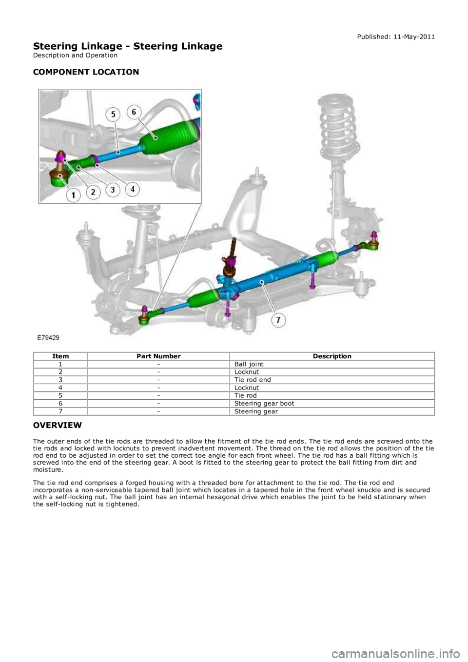
COMPONENT LOCATION
ItemPart NumberDescription
1-Ball joi nt2-Locknut
3-Tie rod end
4-Locknut5-Tie rod
6-Steeri ng gear boot
7-Steeri ng gear
OVERVIEW
The outer ends of the t ie rods are threaded t o al low t he fit ment of t he t ie rod ends. The t ie rod ends are s crewed onto t het ie rods and locked wit h locknut s t o prevent inadvertent movement. The t hread on t he t ie rod all ows the pos it ion of t he t ierod end to be adjust ed i n order t o s et the correct t oe angle for each front wheel. The t ie rod has a ball fit ti ng which i ss crewed int o t he end of the s t eering gear. A boot is fit ted t o t he s teering gear to protect t he bal l fi tt ing from dirt andmois t ure.
The t ie rod end compris es a forged hous ing wi th a t hreaded bore for at tachment to the t ie rod. The t ie rod endincorporat es a non-s ervi ceable t apered ball joint which l ocat es in a tapered hol e in the front wheel knuckl e and i s s ecuredwit h a sel f-locki ng nut. The ball joint has an int ernal hexagonal drive which enables t he joi nt to be hel d s t at ionary whent he sel f-locki ng nut is t ight ened.
Page 568 of 3229
t he s ame number of t urns as when removed.
Inst all t he ti e-rod end.
2. W ARNING: Make sure t hat a new t ie-rod end nut is
i ns t alled.
• CAUTIONS: Make s ure that t he mat ing faces are clean and free of foreign
mat eri al . Make s ure that t he ball joi nt bal l does not rot ate.
Connect t he ti e-rod end ball joi nt.
T orque: 70 Nm 2.
3. CAUTION: Make s ure that the mati ng faces are cl ean and
free of foreign mat eri al.
Tight en the ti e-rod locki ng nut.
T orque: 55 Nm 3.
Inst all t he front wheel .
Refer t o: W heel and Ti re (204-04 W heel s and Tires, Removal and
Inst all at ion).
4.
Us ing onl y four wheel al ignment equi pment approved by Land Rover,
check and adjus t t he wheel al ignment.
5.