Page 606 of 3229

Cont rol Module (ECM) cont rols t he fuel injection s ys t em and t he ignit ion s yst em.
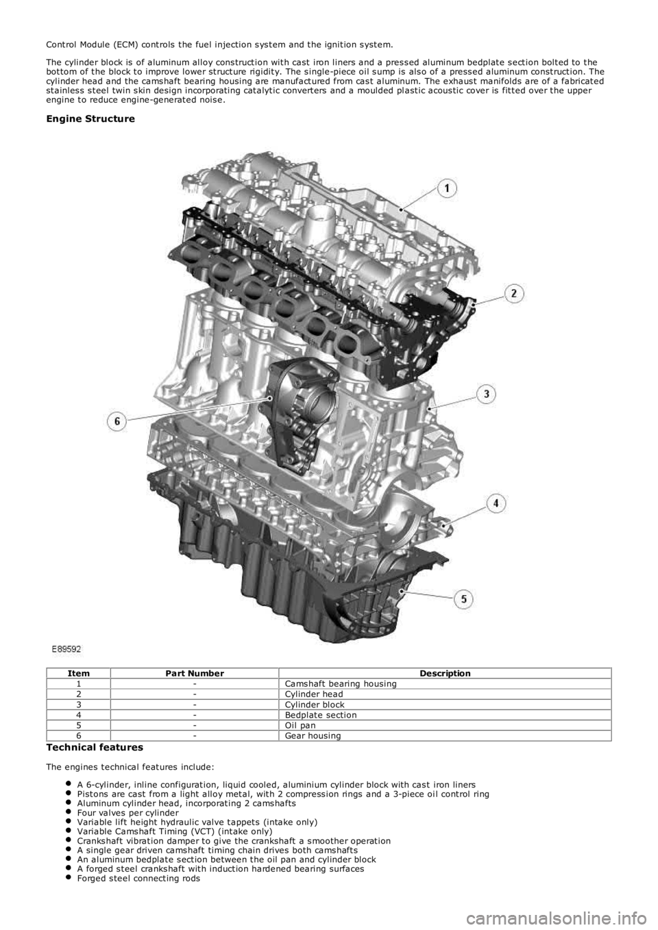
The cylinder block is of aluminum alloy cons truct ion wit h cast iron liners and a pres s ed aluminum bedplat e s ect ion bolt ed to t hebot tom of t he block t o improve lower st ruct ure rigidit y. The s ingle-piece oil s ump is als o of a press ed aluminum const ruct ion. Thecylinder head and the cams haft bearing housing are manufact ured from cas t aluminum. The exhaus t manifolds are of a fabricat edst ainles s s t eel twin s kin design incorporat ing cat alyt ic convert ers and a moulded plast ic acous tic cover is fit t ed over t he upperengine t o reduce engine-generat ed nois e.
Engine Structure
ItemPart NumberDescription1-Cams haft bearing housing2-Cylinder head3-Cylinder block4-Bedplat e section5-Oil pan6-Gear housing
Technical features
The engines t echnical feat ures include:
A 6-cylinder, inline configurat ion, liquid cooled, aluminium cylinder block wit h cast iron linersPist ons are cast from a light alloy met al, wit h 2 compress ion rings and a 3-piece oil cont rol ringAluminum cylinder head, incorporat ing 2 cams haftsFour valves per cylinderVariable lift height hydraulic valve t appet s (intake only)Variable Cams haft Timing (VCT) (int ake only)Cranks haft vibrat ion damper t o give the crankshaft a s moother operat ionA single gear driven cams haft timing chain drives both cams haft sAn aluminum bedplat e s ect ion between t he oil pan and cylinder blockA forged s t eel cranks haft wit h induct ion hardened bearing surfacesForged s teel connect ing rods
Page 607 of 3229
A Rear End Ancillary Drive (READ) s yst emTwo fabricated s t ainles s s t eel t win s kin exhaust manifoldsA 3-pos ition Variable Intake Sys t em (VIS)An advanced Engine Management Syst em (EMS) incorporat ing elect ronic t hrot tle controlFour cat alyt ic converters
Technical data
DESCR IPT IO NT YPEConfigurationInline 6-cylinderO utput171 kW at 6200 rpmT orque320 Nm at 3200 rpmDisplacement3192 cm³Stroke/bore96.0 mm/84.0 mmCompression ratio10.8:1Firing order1-5-3-6-2-4Approximate weight180 kg (including int ake pipe, exhaus t manifold, alt ernator and oil)
ItemPart NumberDescriptionA-Torque (Nm)B-Power (kW )
CYLINDER BLOCK COMPONENTS
The main cylinder block components are:
Cylinder blockConnect ing rods and pis tonsPist on cooling jet sGenerat orGear hous ingThermos tat hous ingCranks haft Pos it ion (CKP) s ensorKnock s ens orsCoolant pumpCoolant inlet pipe
Cylinder Numbering
The cylinders are numbered as shown below, wit h cylinder 1 at t he front of the engine.
Page 608 of 3229
Cylinder Block
ItemPart NumberDescription1-Identificat ion markingsThe cylinders and crankcas e are cont ained in t he cylinder block, which is of a cas t aluminum cons truct ion. The cylinder sleeves aremade of cas t iron and cast in bores. The cylinder block is of a pen coolant mant le design, which allows coolant t o flow freelyaround t he upper s ect ion of the cylinders .
Connecting rods and Pistons
Page 610 of 3229
ItemPart NumberDescription1-Pis t on cooling jet (6 off)Jet s locat ed in the cylinder block s pray oil on t o t he ins ide of t he pis ton t o provide pis t on and pis ton pin lubricat ion and cooling.The oil is dist ribut ed through t he cylinder block, via t he main oil gallery and channels bored in t he block.
Generator
ItemPart NumberDescription1-Rubber s leeve2-GeneratorThe generat or is locat ed at the rear of t he int ake side of t he cylinder block. The generator is driven by the crankshaft gearwheelvia t he auxiliary unit shaft gearwheel and t he auxiliary unit inner shaft gear wheel (s ee gear housing s ect ion for moreinformat ion).
Gear Housing Components
Page 613 of 3229

The intermediat e s haft is us ed to locat e the cams haft drive s haft gear wheel in t he cylinder block. The shaft is journaled wit h adouble conical roller bearing. The auxiliary unit s haft drive gear wheel is in 2 pieces , wit h t he narrow half being s pring tensioned inthe opposit e direct ion t o t he wide half. This feat ure reduces nois e becaus e gear play is eliminat ed. Only t he wide half drives theauxiliary unit's gear wheel. The cams haft chain gear wheel is of t he conventional design.
The s haft is sealed against the exhaust side (i.e. the rear s ide of t he cylinder block) by a s ealing was her. To remove or inst all t hewasher, t he flywheel/flexplate must be removed.
Camshaft Drive O uter Shaft
The cams haft drive outer s haft is journaled at the front end of t he s haft with a double row bearing in t he gear hous ing. Needlebearings are us ed at t he rear end (pulley s ide) against t he auxiliary unit s haft . The camshaft drive out er s haft gear wheel is in 2pieces , a wide and a narrow half t o reduce nois e. The cams haft chain gear wheel is als o locat ed on the s haft and is us ed to drivethe cams hafts chain.
Auxiliary Unit Inner Shaft
The auxiliary unit inner s haft is journaled at t he front end of t he shaft (generator s ide) in t he gear housing with a s ingle rowbearing. Needle bearings are used at the rear end (pulley s ide) against the cams haft drive shaft . There is a pulley at t he rear endof the s haft that drives t he Air Condit ioning (AC) compress or and the power s t eering pump, via a polyvee belt . The shaft als odrives t he generat or at t he front end, via a sleeve connect or.
Thermostat Housing
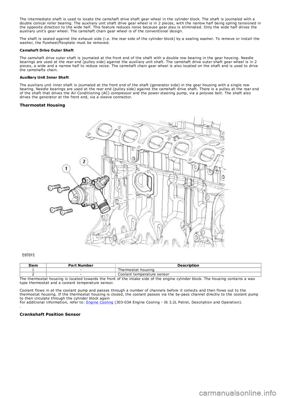
ItemPart NumberDescription1-Thermost at hous ing2-Coolant t emperat ure s ens orThe t hermos tat hous ing is located t owards the front of t he int ake s ide of t he engine cylinder block. The hous ing contains a waxtype t hermost at and a coolant temperat ure sens or.
Coolant flows in at t he coolant pump and pas s es through a number of channels before it collect s and t hen flows out t o t hethermos t at housing. If t he t hermost at hous ing is closed, t he coolant pass es via t he by-pass channel directly to t he coolant pumpto then circulat e t hrough t he cylinder block againFor addit ional information, refer t o: Engine Cooling (303-03A Engine Cooling - I6 3.2L Pet rol, Des cription and Operat ion)..
Crankshaft Position Sensor
Page 614 of 3229
ItemPart NumberDescription1-CKP s ens or2-Sensor bracketThe Cranks haft Posit ion (CKP) sensor is locat ed at t he rear of the int ake s ide of t he cylinder block. The s ens or provides an input ofengine crankshaft speed and pos it ion. The sensor works on t he principle of t he Hall effect and s cans a trigger wheel (magnet icdis c) on t he flywheelFor addit ional information, refer t o: Elect ronic Engine Cont rols (303-14A Elect ronic Engine Controls - I6 3.2L Pet rol, Des cript ion andOperation)..
Knock Sensors
Page 615 of 3229
ItemPart NumberDescription1-Front knock s ens or2-Rear knock s ens orThe knock s ens ors are locat ed at t he front and rear int ake side of t he cylinder block. They are piezo-elect ric s ens ors t hat provideinput s t o detect and locate det onation during combust ionFor addit ional information, refer t o: Elect ronic Engine Cont rols (303-14A Elect ronic Engine Controls - I6 3.2L Pet rol, Des cript ion andOperation)..
Coolant Pump
Page 616 of 3229

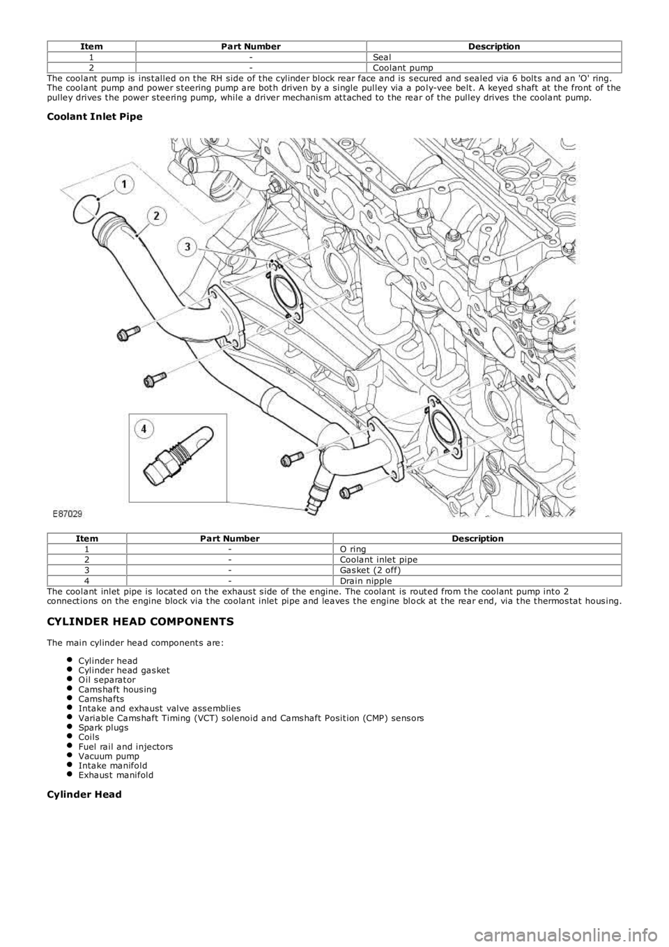
ItemPart NumberDescription1-Seal2-Coolant pumpThe coolant pump is ins t alled on t he RH side of t he cylinder block rear face and is s ecured and s ealed via 6 bolt s and an 'O' ring.The coolant pump and power s t eering pump are bot h driven by a single pulley via a poly-vee belt . A keyed s haft at the front of t hepulley drives t he power s teering pump, while a driver mechanism at t ached to t he rear of t he pulley drives the coolant pump.
Coolant Inlet Pipe
ItemPart NumberDescription1-O ring2-Coolant inlet pipe3-Gas ket (2 off)4-Drain nippleThe coolant inlet pipe is locat ed on t he exhaus t s ide of the engine. The coolant is rout ed from t he coolant pump int o 2connect ions on the engine block via t he coolant inlet pipe and leaves t he engine block at t he rear end, via t he t hermos tat hous ing.
CYLINDER HEAD COMPONENTS
The main cylinder head component s are:
Cylinder headCylinder head gas ketO il s eparat orCams haft hous ingCams haftsIntake and exhaust valve ass embliesVariable Cams haft Timing (VCT) s olenoid and Cams haft Posit ion (CMP) sens orsSpark plugsCoilsFuel rail and injectorsVacuum pumpIntake manifoldExhaus t manifold
Cylinder Head