2006 LAND ROVER FRELANDER 2 check engine
[x] Cancel search: check enginePage 1043 of 3229
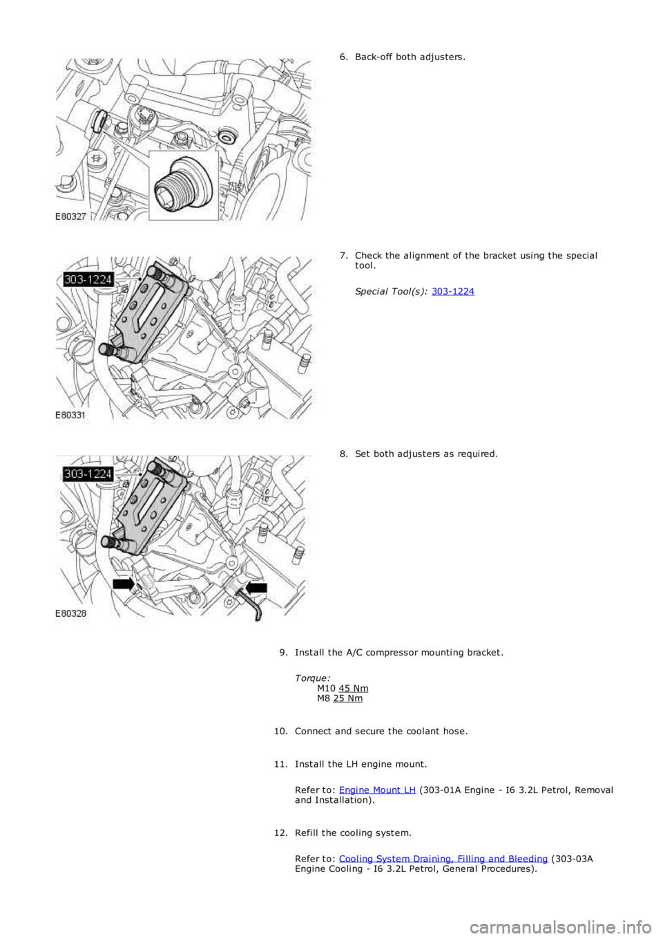
Back-off both adjus ters .
6. Check the al ignment of the bracket usi ng t he special
t ool .
Speci al Tool (s ): 303-1224 7.
Set both adjus t ers as requi red.
8.
Inst all t he A/C compress or mounti ng bracket .
T orque: M10 45 Nm M8
25 Nm 9.
Connect and s ecure t he cool ant hos e.
10.
Inst all t he LH engine mount.
Refer t o: Engi ne Mount LH (303-01A Engine - I6 3.2L Petrol, Removal
and Inst all at ion).
11.
Refi ll t he cool ing s yst em.
Refer t o: Cool ing Sys tem Drai ni ng, Fi lli ng and Bleeding (303-03A
Engine Cooli ng - I6 3.2L Petrol, General Procedures).
12.
Page 1069 of 3229
Publi s hed: 11-May-2011
Accessory Drive - TD4 2.2L Diesel - Accessory Drive
Diagnosi s and Tes ti ng
Principles of Operation
For a detail ed descripti on of the Front End Access ory Dri ve (FEAD), refer t o t he relevant Descripti on and Operat ion s ect ionof the workshop manual.REFER to: Acces s ory Drive (303-05B Acces s ory Drive - TD4 2.2L Dies el, Des cript ion and Operat ion).
Inspection and Verification
1. Verify t he cus t omer concern.1.
2. Vis ually ins pect for s ys tem int egrit y and obvi ous s igns of damage.2.
Visual Inspection
Mechanical
FEAD beltFEAD belt t ensi onFEAD belt t ensi onerFEAD belt pull eysFEAD belt pull ey s eal s
3. If an obvious cause for an obs erved or report ed concern is found, correct t he caus e (if pos s ible) beforeproceeding t o t he next s t ep3.
4. If t he caus e is not vis ually evi dent , verify t he sympt om and refer t o t he Sympt om Chart.4.
Symptom Chart
SymptomPossible CauseAction
FEAD belt nois e ors quealFEAD belt pull ey(s )Lubricant or othercont ami nat ionFEAD belt
Check for pull ey alignment , freedom of rotat ion and damage. Repai ror i ns t all new part s as requi red.REFER t o: Access ory Dri ve Belt (303-05B Acces sory Dri ve - TD4 2.2LDi esel , Removal and Ins t allat ion) /Acces s ory Drive Bel t Tens ioner (303-05B Acces sory Dri ve - TD4 2.2LDi esel , Removal and Ins t allat ion) /Acces s ory Drive Bel t Idl er Pul ley (303-05B Acces sory Dri ve - TD42.2L Dies el, Removal and Ins tall ati on).Check FEAD belt for contami nat ion. If cont aminated, ins t al l a newbelt .REFER t o: Access ory Dri ve Belt (303-05B Acces sory Dri ve - TD4 2.2LDi esel , Removal and Ins t allat ion).Check FEAD belt for correct appli cat ionFEAD belt does nothold tens ionFEAD belt cracking ordamagedTensi oner worn ordamaged
Ins pect FEAD belt for cracking or damage. Ins tal l a new belt asrequi red.REFER t o: Access ory Dri ve Belt (303-05B Acces sory Dri ve - TD4 2.2LDi esel , Removal and Ins t allat ion).Check FEAD belt t ens ioner for damage and correct operat ion. Ins t al la new FEAD belt t ens i oner as requi red.REFER t o: Access ory Dri ve Belt Tensi oner (303-05B Acces s ory Drive -TD4 2.2L Dies el, Removal and Ins tal lati on).
Component Tests
FEAD belt tensioner
Stat ic
The only checks requi red for the FEAD bel t tens ioner are for st ick, grab or bind.
1. Remove the drive belt i n t he area of t he t ens ioner.1.
2. Us ing t he correct t ool , rot at e t he t ens ioner from it s rel axed pos it ion t hrough it s full s troke and back t o t herelaxed posi ti on to make s ure t here i s no s t ick, grab or bind, and to make s ure t hat there is t ensi on on t het ensi oner s pri ng.
2.
3. If t he t ens i oner meet s the above cri teria, proceed to the dynamic t es t. If the tens ioner does not meet t he abovecrit eria ins tall a new t ens ioner.REFER t o: Access ory Dri ve Belt Tensi oner (303-05B Acces s ory Drive - TD4 2.2L Dies el, Removal and Ins tall ati on).
3.
Dynamic
The FEAD belt t ens i oner can be checked dynami cal ly as foll ows:
W i th the engine running, obs erve drive belt t ensi oner movement , the FEAD belt t ensi oner s hould move (res pond) when theair condi ti oni ng clut ch cycles (if equipped), t he FEAD bel t tens ioner s hould move (res pond) when t he engi ne s peed isincreas ed rapi dl y. If t he dri ve bel t tens ioner movement i s errati c wit hout ai r condit ioni ng cl utch cycl ing or engineaccelerati on, a pul ley or s haft may be bent , or di st ort ed. Excess i ve drive bel t ri deout (uneven dept h of grooves in the drivebelt ) can al s o caus e exces s ive drive belt t ensi oner movement. Check condi ti on by instal ling a known good bel t.REFER to: Acces s ory Drive Bel t (303-05B Acces s ory Drive - TD4 2.2L Di es el, Removal and Ins t al lat ion).
Page 1070 of 3229

FEAD belt
1. W i th the engine off, check routi ng of the drive belt .REFER t o: Access ory Dri ve (303-05B Access ory Dri ve - TD4 2.2L Di esel , Des cri pti on and Operati on).1.
2. Ins pect t he dri ve belt t ens i oner wear indicator t o confirm the drive belt i s wi thin operati ng range. Ins tal l a newdrive belt as necess ary .REFER t o: Access ory Dri ve Belt (303-05B Acces sory Dri ve - TD4 2.2L Dies el , Removal and Inst all at ion).
2.
Page 1076 of 3229
Publi s hed: 11-May-2011
Starting System - I6 3.2L Petrol - Starting System
Des cript ion and Operat ion
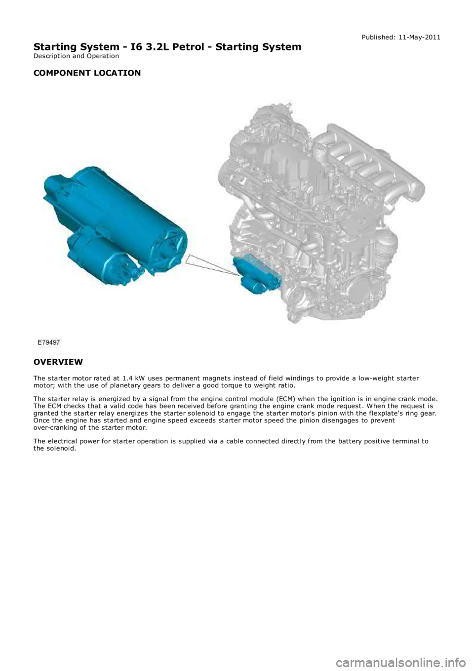
COMPONENT LOCATION
OVERVIEW
The s tarter mot or rated at 1.4 kW uses permanent magnet s ins tead of field windings to provide a low-weight s tartermot or; wi th t he us e of planetary gears t o deli ver a good t orque t o weight rati o.
The s tarter rel ay is energi zed by a s ignal from t he engine cont rol module (ECM) when t he i gni ti on is i n engine crank mode.The ECM checks t hat a valid code has been received before grant ing t he engine crank mode reques t . W hen t he request i sgrant ed the s t art er relay energi zes t he s t arter s olenoid to engage t he st art er motor's pi ni on wi th t he flexplate's ri ng gear.Once the engi ne has st art ed and engine s peed exceeds st art er motor s peed the pi nion di sengages to preventover-cranking of t he s t arter mot or.
The electrical power for st art er operat ion is s upplied vi a a cable connect ed direct ly from t he bat t ery pos it ive t ermi nal t ot he sol enoi d.
Page 1077 of 3229
Publi s hed: 11-May-2011
Starting System - I6 3.2L Petrol - Starting System
Diagnosi s and Tes ti ng
Principles of Operation
For a detail ed descripti on of the st art ing s ys tem, refer t o the relevant Descri pti on and Operat ion s ect ion in t he works hopmanual.REFER to: St art ing Syst em (303-06A St art ing Sys tem - I6 3.2L Petrol, Des cript ion and Operat ion) /Starti ng Sys t em (303-06B St arti ng Syst em - TD4 2.2L Di es el, Des cri pt ion and Operati on).
Inspection and Verification
CAUTION: Di agnos is by s ubs ti tut ion from a donor vehicle is NO T acceptabl e. Subs ti tut ion of cont rol modules doesnot guarant ee confirmat ion of a faul t, and may als o caus e addit ional fault s i n t he vehi cl e being t est ed and/or t he donorvehi cl e.
1. Verify t he cus t omer concern.1.
2. Vis ually ins pect for obvious s igns of mechani cal or electrical damage.2.
Visual Inspection
MechanicalElectrical
Gear s el ect or lever cable adjust mentSt arter Mot orBatt ery
Bat teryFus esW iring harnes sDamaged, loos e or corroded connectorsSt art er relayEngine Cont rol Module (ECM)
3. If an obvious cause for an obs erved or report ed concern is found, correct t he caus e (if pos s ible) beforeproceeding t o t he next s t ep3.
4. If t he caus e is not vis ually evi dent , verify t he sympt om and refer t o t he Sympt om Chart, al ternat ively, check forDi agnos ti c Trouble Codes (DTCs) and refer t o t he DTC Index.4.
Symptom Chart
SymptomPossible CauseAction
The engine does notcrank (s tart er mot ordoes not t urn)
Gear s el ect or not i n Por N pos it ionBatt eryHarnes s /Connect orsSt arter mot orSt arter relaySt art s wit chTrans mi ss ion cont rolmodule (TCM)Engine control modul e(ECM)Engine s eized
Make s ure the gear s elector is in t he P or N posi ti on and correct lyadjus t ed.REFER t o: Sel ect or Lever Cabl e Adjus t ment (307-05 Aut omati cTrans mi s si on/Trans axl e External Controls , General Procedures ).Check the bat tery condi ti on and s tat e of charge.REFER t o: Bat t ery (414-01 Batt ery, Mounti ng and Cabl es, Di agnos isand Tes ti ng).Check the st art er motor and harnes s . Check for DTCs and refer t orelevant DTC Index
The engine does notcrank (s tart er mot ordoes t urn)
St arter mot ori ns t allat ionSt arter mot orRing gear
Check the st art er motor i ns t allat ion (fas t eners t ight, s t arter mot ors quare t o engine, etc). Check t he ri ng gear t eeth for damage,foreign object s , et c.
Engine cranks t oos lowl yBatt eryHarnes s /Connect orsSt arter mot orEngine oil i ncorrectgrade
Check the bat tery condi ti on and s tat e of charge.REFER t o: Bat t ery (414-01 Batt ery, Mounti ng and Cabl es, Di agnos isand Tes ti ng).Refer t o t he electrical ci rcuit di agrams and t est t he s tarter mot orand s t art er motor circuit s
Engine cranks t oo fas tLow enginecompres s ionCheck the engi ne compress i ons .REFER t o: Engi ne (303-00 Engine Sys t em - General Informat ion,Di agnos is and Tes t ing).Exces s ive s t artermot or noi seSt arter mot orSt arter mot ori ns t allat ion/cas ingRing gear
Check the st art er motor i ns t allat ion (fas t eners t ight, mot or squaret o engine, etc). Check t he s tart er mot or cas ing condi ti on. Check t hering gear t eet h for damage, foreign objects , et c.
DTC Index
• NOTE: If the control modul e or a component i s s us pect and the vehicle remains under manufacturer warrant y, refer t o theW arranty Pol icy and Procedures manual (s ect ion B1.2), or determine i f any pri or approval programme is in operat ion, pri ort o the ins tall ati on of a new module/component.
• NOTE: Generic scan t ool s may not read the codes li st ed, or may read only fi ve digit codes . Mat ch the five di git s from t hes can tool to the firs t fi ve di git s of the seven digi t code l is ted to ident ify t he faul t (t he las t t wo digi ts gi ve addi ti onal
Page 1079 of 3229
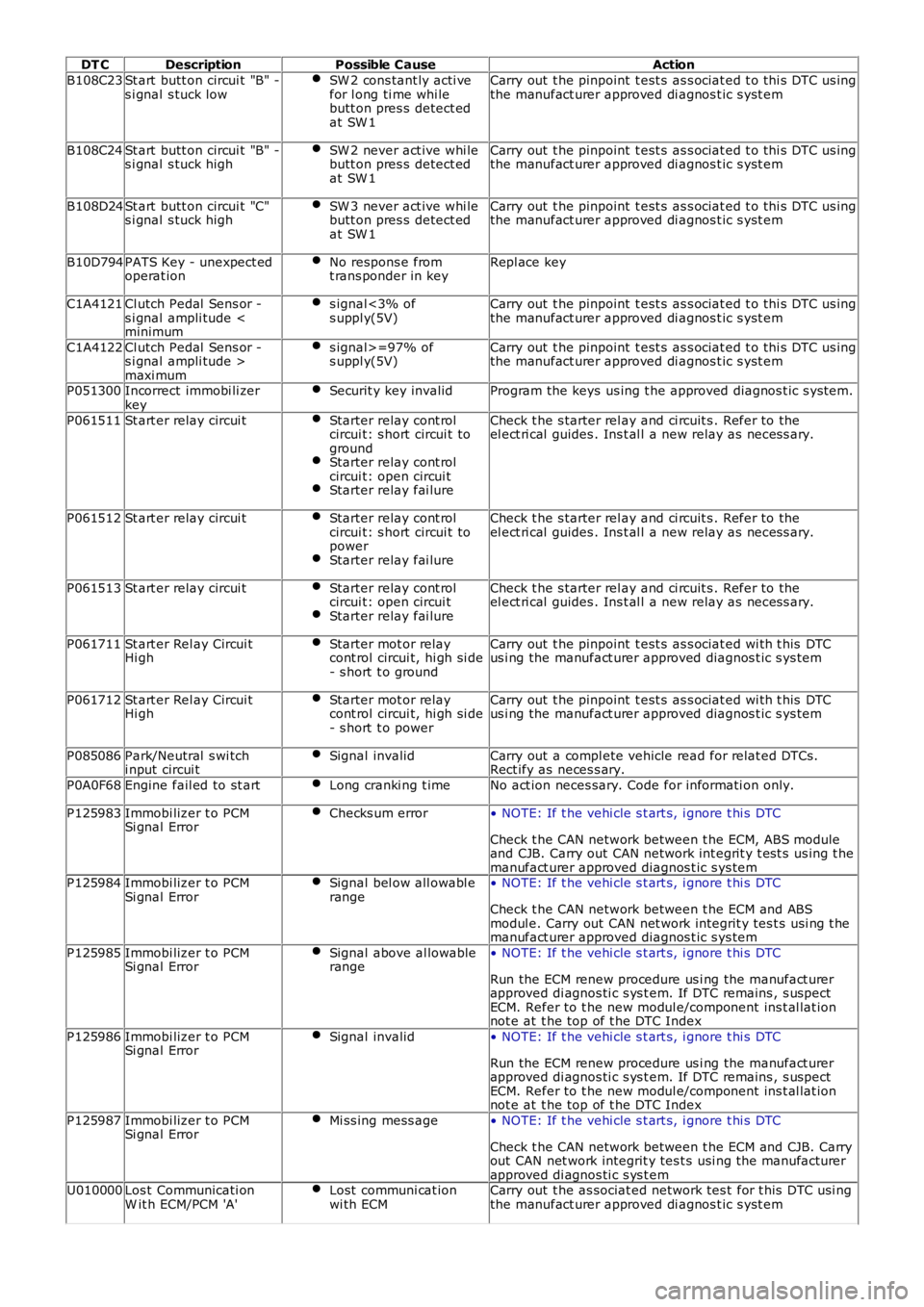
DT CDescriptionPossible CauseAction
B108C23St art butt on circui t "B" -s i gnal s tuck lowSW 2 cons tant ly acti vefor l ong ti me whi lebutt on pres s detect edat SW 1
Carry out t he pinpoint t est s as s ociat ed t o t hi s DTC us ingthe manufact urer approved di agnos t ic s yst em
B108C24St art butt on circui t "B" -s i gnal s tuck highSW 2 never act ive whi lebutt on pres s detect edat SW 1
Carry out t he pinpoint t est s as s ociat ed t o t hi s DTC us ingthe manufact urer approved di agnos t ic s yst em
B108D24St art butt on circui t "C"s i gnal s tuck highSW 3 never act ive whi lebutt on pres s detect edat SW 1
Carry out t he pinpoint t est s as s ociat ed t o t hi s DTC us ingthe manufact urer approved di agnos t ic s yst em
B10D794PATS Key - unexpect edoperat ionNo respons e fromt rans ponder in keyRepl ace key
C1A4121Cl utch Pedal Sens or -s i gnal ampli tude
C1A4122Cl utch Pedal Sens or -s i gnal ampli tude >maxi mum
s ignal>=97% ofs uppl y(5V)Carry out t he pinpoint t est s as s ociat ed t o t hi s DTC us ingthe manufact urer approved di agnos t ic s yst em
P051300Incorrect immobi li zerkeySecurit y key invalidProgram the keys us ing t he approved diagnos t ic s yst em.
P061511St art er relay circui tStarter relay cont rolcircui t: s hort circui t togroundStarter relay cont rolcircui t: open circui tStarter relay fai lure
Check t he s tarter rel ay and ci rcuit s . Refer to theel ect ri cal guides . Ins t al l a new relay as neces s ary.
P061512St art er relay circui tStarter relay cont rolcircui t: s hort circui t topowerStarter relay fai lure
Check t he s tarter rel ay and ci rcuit s . Refer to theel ect ri cal guides . Ins t al l a new relay as neces s ary.
P061513St art er relay circui tStarter relay cont rolcircui t: open circui tStarter relay fai lure
Check t he s tarter rel ay and ci rcuit s . Refer to theel ect ri cal guides . Ins t al l a new relay as neces s ary.
P061711St art er Rel ay Circui tHi ghStarter mot or relaycont rol circui t, hi gh si de- s hort t o ground
Carry out t he pinpoint t est s as s ociat ed wi th t his DTCus i ng the manufact urer approved diagnos t ic s ys tem
P061712St art er Rel ay Circui tHi ghStarter mot or relaycont rol circui t, hi gh si de- s hort t o power
Carry out t he pinpoint t est s as s ociat ed wi th t his DTCus i ng the manufact urer approved diagnos t ic s ys tem
P085086Park/Neutral s wi tchi nput circui tSignal invalidCarry out a compl ete vehicle read for relat ed DTCs.Rect ify as neces s ary.
P0A0F68Engine fail ed to st artLong cranki ng t imeNo act ion neces sary. Code for informati on only.
P125983Immobi lizer t o PCMSi gnal ErrorChecks um error• NOTE: If t he vehi cle s t art s, i gnore t hi s DTC
Check t he CAN network between t he ECM, ABS moduleand CJB. Carry out CAN network int egrit y t est s us ing t hemanufact urer approved diagnos t ic s ys temP125984Immobi lizer t o PCMSi gnal ErrorSignal bel ow all owabl erange• NOTE: If t he vehi cle s t art s, i gnore t hi s DTC
Check t he CAN network between t he ECM and ABSmodul e. Carry out CAN net work integrit y tes t s usi ng t hemanufact urer approved diagnos t ic s ys tem
P125985Immobi lizer t o PCMSi gnal ErrorSignal above al lowablerange• NOTE: If t he vehi cle s t art s, i gnore t hi s DTC
Run the ECM renew procedure us i ng the manufact urerapproved di agnos ti c s ys t em. If DTC remains , s uspectECM. Refer to t he new modul e/component ins t al lat ionnot e at t he top of t he DTC Index
P125986Immobi lizer t o PCMSi gnal ErrorSignal invalid• NOTE: If t he vehi cle s t art s, i gnore t hi s DTC
Run the ECM renew procedure us i ng the manufact urerapproved di agnos ti c s ys t em. If DTC remains , s uspectECM. Refer to t he new modul e/component ins t al lat ionnot e at t he top of t he DTC Index
P125987Immobi lizer t o PCMSi gnal ErrorMi ss ing mess age• NOTE: If t he vehi cle s t art s, i gnore t hi s DTC
Check t he CAN network between t he ECM and CJB. Carryout CAN net work integrit y tes t s usi ng t he manufacturerapproved di agnos ti c s ys t emU010000Los t Communicati onW it h ECM/PCM 'A'Lost communi cat ionwi th ECMCarry out t he as sociat ed network tes t for t his DTC usi ngthe manufact urer approved di agnos t ic s yst em
Page 1087 of 3229
Publi s hed: 11-May-2011
Starting System - TD4 2.2L Diesel - Starting System
Des cript ion and Operat ion
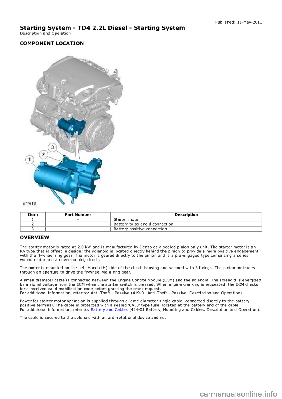
COMPONENT LOCATION
ItemPart NumberDescription
1-St art er motor2-Bat tery to sol enoi d connecti on
3-Bat tery pos i ti ve connect ion
OVERVIEW
The s tarter mot or is rated at 2.0 kW and is manufact ured by Dens o as a s ealed pi ni on only unit . The s tarter mot or is anRA t ype that i s offset i n desi gn; the s olenoid is l ocat ed direct ly behind t he pini on to provide a more pos it ive engagementwit h t he flywheel ring gear. The mot or is geared direct ly t o t he pinion and is a pre-engaged type compri si ng a s eri eswound mot or and an over-running cl utch.
The mot or i s mounted on the Left-Hand (LH) s ide of t he clut ch hous ing and s ecured with 3 fi xings. The pi nion prot rudest hrough an aperture t o dri ve the fl ywheel via a ri ng gear.
A s mal l di ameter cabl e i s connected bet ween the Engine Cont rol Modul e (ECM) and the s olenoid. The s olenoid i s energizedby a s i gnal volt age from t he ECM when t he s tarter s wit ch is pres sed. W hen engine cranking is reques ted, t he ECM checksfor a recei ved val id mobi li zat ion code before grant ing t he crank reques t.For addit ional informat ion, refer t o: Anti -Theft - Pas s ive (419-01 Anti -Theft - Pas sive, Des cri pti on and Operati on).
Power for s tarter mot or operat ion i s s uppl ied t hrough a l arge di ameter s ingle cable, connected di rectl y t o t he bat t eryposi ti ve terminal . The cable is prot ected wi th a s eal ed 'CAL3' type fus e, located at t he batt ery end of t he cable.For addit ional informat ion, refer t o: Batt ery and Cables (414-01 Bat tery, Mounti ng and Cables , Des cri pti on and Operati on).
The cabl e is secured t o t he s olenoid wi th an anti -rotat ional device and nut.
Page 1106 of 3229
CAUTION: To avoid damage/malfuncti oni ng of the BMS module, always us e a s uit able body ground point rather thant he bat t ery negat ive terminal when connect ing a s lave power supply.
For addit ional informat ion, refer t o: Batt ery (414-01 Bat tery, Mounti ng and Cables , Diagnos is and Tes t ing).
Gear Neutral Sensor
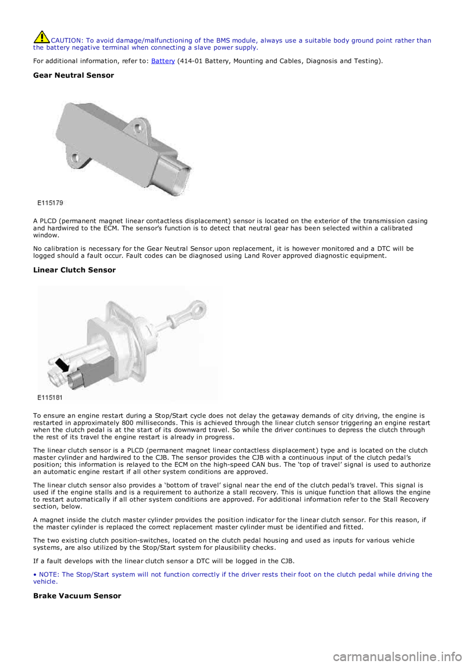
A PLCD (permanent magnet l inear cont act les s dis placement) s ensor i s located on the exterior of the trans mi s si on cas i ngand hardwired t o t he ECM. The sens or’s functi on is t o det ect t hat neut ral gear has been s elected wi thi n a cali bratedwindow.
No cali brati on is neces sary for t he Gear Neut ral Sensor upon repl acement, i t is however monit ored and a DTC wil l belogged s houl d a fault occur. Fault codes can be diagnos ed us ing Land Rover approved di agnos ti c equi pment.
Linear Clutch Sensor
To ens ure an engine res tart during a St op/St art cycl e does not del ay the get away demands of cit y dri ving, the engine i sres t art ed in approximately 800 mil li seconds . This i s achi eved through t he li near clut ch s ens or triggeri ng an engine rest artwhen t he cl utch pedal is at t he s tart of i ts downward t ravel. So whil e t he dri ver conti nues t o depres s t he clutch t hrought he res t of it s t ravel t he engine rest art i s already i n progress .
The li near clut ch s ens or is a PLCD (permanent magnet li near contactl es s di spl acement) type and i s located on t he clut chmas ter cylinder and hardwired t o t he CJB. The s ensor provi des t he CJB wi th a cont inuous input of the clut ch pedal ’sposi ti on; this informati on is relayed t o t he ECM on t he high-speed CAN bus . The ‘t op of travel ’ si gnal i s used to aut horizean automat ic engine res tart if all ot her s ys tem condit ions are approved.
The li near clut ch s ens or als o provides a ‘bott om of t ravel’ s ignal near t he end of the cl ut ch pedal ’s t ravel. This si gnal i sus ed if t he engi ne s tal ls and i s a requi rement t o authori ze a s tal l recovery. This is unique funct ion t hat allows the enginet o res t art automat ically if all ot her s ys tem condit ions are approved. For addi ti onal i nformat ion refer t o t he Stall Recoverys ect ion, below.
A magnet ins ide the clut ch mas ter cylinder provides t he posi ti on indicator for the linear cl utch s ensor. For t his reason, ift he mas ter cyl inder is replaced the correct replacement mas t er cyli nder mus t be i dent ified and fit t ed.
The t wo exis ti ng clutch pos it ion-s wi tches, l ocat ed on t he cl utch pedal hous ing and us ed as i nput s for vari ous vehi cl es ys t ems , are al so ut il ized by t he Stop/Start sys tem for pl aus ibi lit y checks .
If a fault develops wi th the l inear cl utch s ensor a DTC wil l be logged in the CJB.
• NOTE: The Stop/Start sys tem wil l not funct ion correctl y if t he dri ver rest s t hei r foot on t he clut ch pedal whil e dri vi ng t hevehi cl e.
Brake Vacuum Sensor