2006 LAND ROVER FRELANDER 2 check engine
[x] Cancel search: check enginePage 1186 of 3229
1
2
3
1
2
3
DT CDescriptionPossible CauseAction
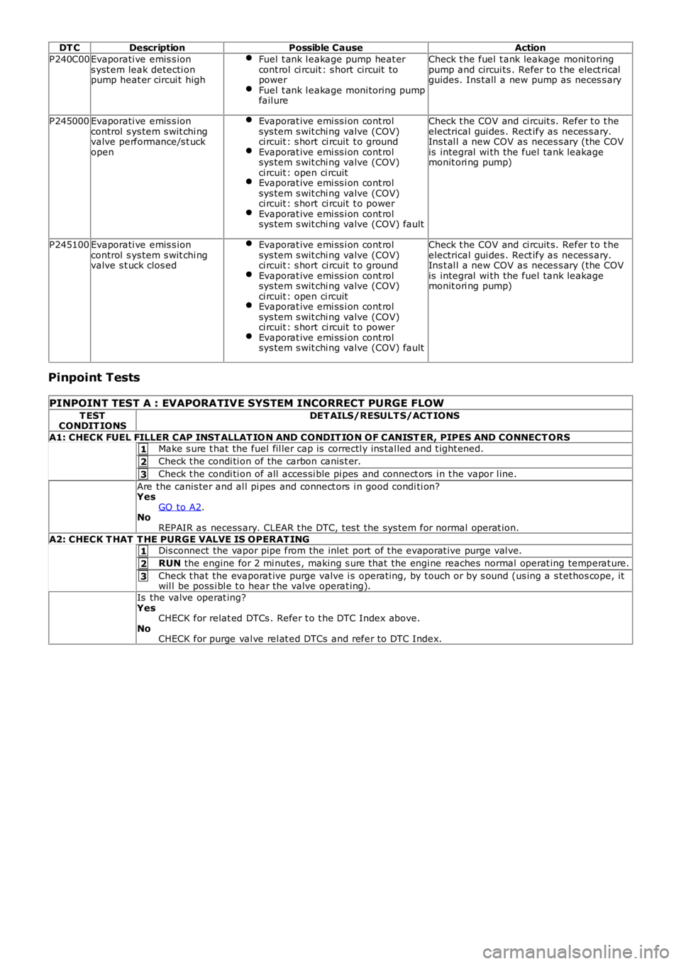
P240C00Evaporati ve emis s ions yst em leak detecti onpump heat er circui t high
Fuel t ank l eakage pump heat ercont rol ci rcuit : s hort circuit topowerFuel t ank l eakage moni toring pumpfail ure
Check t he fuel t ank leakage moni toringpump and circui ts . Refer t o t he elect ricalguides. Ins tall a new pump as neces s ary
P245000Evaporati ve emis s ioncontrol s ys tem s wit chi ngvalve performance/s t uckopen
Evaporat ive emi ss i on cont rolsys tem s wit chi ng valve (COV)ci rcuit : s hort ci rcuit t o groundEvaporat ive emi ss i on cont rolsys tem s wit chi ng valve (COV)ci rcuit : open ci rcuitEvaporat ive emi ss i on cont rolsys tem s wit chi ng valve (COV)ci rcuit : s hort ci rcuit t o powerEvaporat ive emi ss i on cont rolsys tem s wit chi ng valve (COV) fault
Check t he COV and ci rcuit s. Refer t o t heelectrical gui des . Rect ify as neces s ary.Ins t al l a new COV as neces s ary (the COVis integral wi th the fuel tank leakagemonit ori ng pump)
P245100Evaporati ve emis s ioncontrol s ys tem s wit chi ngvalve s t uck clos ed
Evaporat ive emi ss i on cont rolsys tem s wit chi ng valve (COV)ci rcuit : s hort ci rcuit t o groundEvaporat ive emi ss i on cont rolsys tem s wit chi ng valve (COV)ci rcuit : open ci rcuitEvaporat ive emi ss i on cont rolsys tem s wit chi ng valve (COV)ci rcuit : s hort ci rcuit t o powerEvaporat ive emi ss i on cont rolsys tem s wit chi ng valve (COV) fault
Check t he COV and ci rcuit s. Refer t o t heelectrical gui des . Rect ify as neces s ary.Ins t al l a new COV as neces s ary (the COVis integral wi th the fuel tank leakagemonit ori ng pump)
Pinpoint Tests
PINPOINT TEST A : EVAPORATIVE SYSTEM INCORRECT PURGE FLOW
T ESTCONDIT IONSDET AILS/RESULT S/ACT IONS
A1: CHECK FUEL FILLER CAP INST ALLAT IO N AND CONDIT IO N OF CANIST ER, PIPES AND CONNECT ORSMake s ure t hat the fuel fil ler cap is correctl y ins tal led and t ight ened.
Check t he condi ti on of the carbon canis t er.
Check t he condi ti on of all acces si ble pi pes and connect ors i n t he vapor l ine.
Are the canis ter and al l pi pes and connect ors i n good condi ti on?YesGO to A2.NoREPAIR as necess ary. CLEAR t he DTC, tes t the sys tem for normal operat ion.
A2: CHECK T HAT T HE PURGE VALVE IS OPERAT INGDis connect the vapor pipe from the inlet port of t he evaporat ive purge val ve.
RUN the engine for 2 mi nutes , making s ure that the engi ne reaches normal operat ing temperat ure.
Check t hat the evaporat ive purge valve i s operat ing, by touch or by s ound (us ing a st ethos cope, itwil l be poss i bl e t o hear the valve operat ing).
Is the valve operat ing?YesCHECK for relat ed DTCs . Refer t o t he DTC Index above.NoCHECK for purge val ve rel at ed DTCs and refer to DTC Index.
Page 1204 of 3229
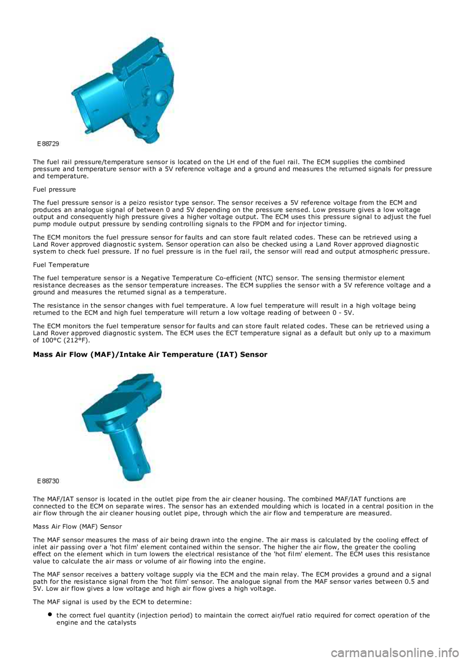
The fuel rai l pres sure/t emperature s ens or is locat ed on t he LH end of t he fuel rai l. The ECM suppli es the combinedpres s ure and t emperat ure s ensor wi th a 5V reference volt age and a ground and meas ures t he ret urned s ignals for pres s ureand t emperature.
Fuel pres s ure
The fuel pres s ure s ens or i s a peizo res is tor t ype sens or. The s ensor receives a 5V reference vol tage from the ECM andproduces an anal ogue s i gnal of between 0 and 5V depending on the pres s ure sens ed. Low pres sure gives a l ow volt ageoutput and cons equent ly hi gh pres s ure gives a hi gher volt age output. The ECM uses t his press ure s ignal t o adjus t t he fuelpump module out put pres sure by s endi ng cont rol ling si gnal s t o the FPDM and for i nject or ti ming.
The ECM moni tors the fuel pres sure s ens or for faul ts and can st ore fault related codes. Thes e can be ret ri eved us i ng aLand Rover approved diagnos t ic s ys tem. Sensor operat ion can als o be checked us i ng a Land Rover approved diagnos t ics ys t em t o check fuel pres sure. If no fuel pres s ure is i n t he fuel rai l, t he s ens or wil l read and output at mospheri c pres s ure.
Fuel Temperat ure
The fuel t emperature s ens or is a Negat ive Temperat ure Co-efficient (NTC) sens or. The s ens i ng thermis t or el ementres is t ance decreas es as the sens or temperat ure increases . The ECM s upplies t he s ensor wi th a 5V reference volt age and aground and meas ures t he ret urned s ignal as a t emperature.
The res is t ance i n t he s ens or changes wi th fuel temperat ure. A l ow fuel t emperat ure wi ll res ult i n a hi gh volt age bei ngret urned t o t he ECM and high fuel temperat ure wil l return a l ow volt age reading of between 0 - 5V.
The ECM moni tors the fuel temperat ure sens or for fault s and can s tore faul t rel at ed codes . These can be ret rieved us ing aLand Rover approved diagnos t ic s ys tem. The ECM us es t he ECT t emperature s ignal as a default but only up to a maximumof 100°C (212°F).
Mass Air Flow (MAF)/Intake Air Temperature (IAT) Sensor
The MAF/IAT s ensor i s located i n t he out let pi pe from t he air cleaner hous ing. The combined MAF/IAT funct ions areconnected t o t he ECM on separat e wi res . The sens or has an ext ended moul ding whi ch is l ocat ed in a cent ral posi ti on in theair flow through t he air cleaner hous ing out let pipe, t hrough which t he air flow and t emperat ure are meas ured.
Mas s Air Flow (MAF) Sensor
The MAF s ensor meas ures t he mas s of air being drawn int o t he engi ne. The ai r mas s is calculat ed by t he cool ing effect ofinl et ai r pas s ing over a 'hot fil m' element cont ained wi thin the s ens or. The higher the ai r fl ow, the great er the cooli ngeffect on the el ement whi ch in t urn lowers the el ect ri cal res i st ance of t he 'hot film' el ement. The ECM us es t his resi s tancevalue t o calcul ate the ai r mass or vol ume of air flowing i nto the engine.
The MAF s ensor receives a bat tery volt age supply vi a t he ECM and t he main relay. The ECM provi des a ground and a s i gnalpath for the res is tance s ignal from t he 'hot film' sens or. The analogue s ignal from t he MAF s ens or varies bet ween 0.5 and5V. Low air flow gi ves a low vol tage and hi gh air fl ow gi ves a high volt age.
The MAF s ignal is us ed by t he ECM t o det ermi ne:
t he correct fuel quant it y (injecti on peri od) t o mai ntain the correct ai r/fuel rat io required for correct operat ion of t heengi ne and t he cat alys ts
Page 1209 of 3229
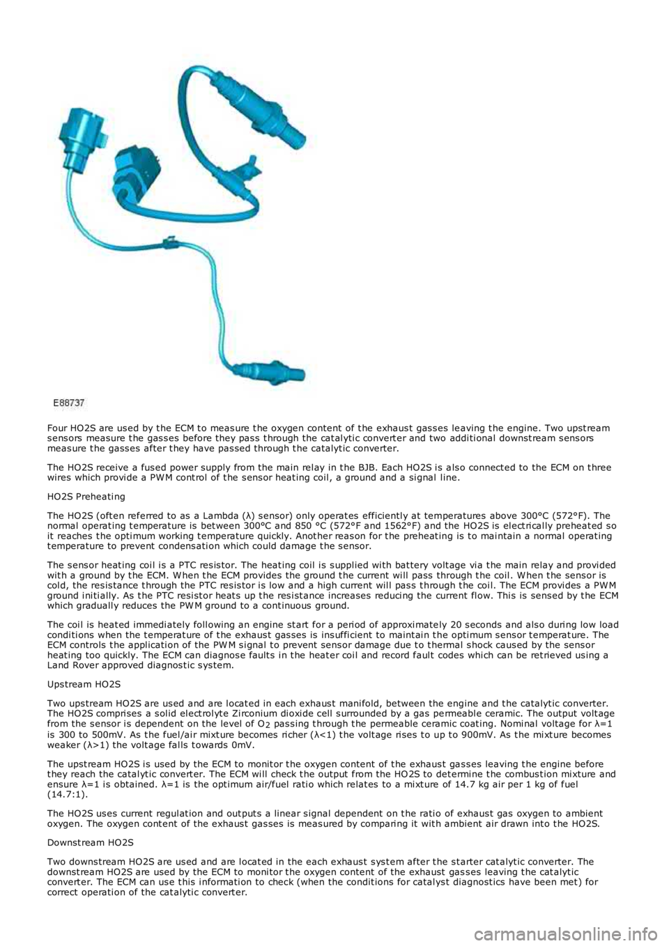
Four HO2S are us ed by t he ECM t o meas ure t he oxygen content of t he exhaus t gas s es leaving t he engine. Two upst reams ens ors measure t he gas s es before they pas s t hrough the cat al yti c convert er and two addi ti onal downst ream s ens orsmeas ure t he gass es after t hey have pas sed through t he catalyt ic converter.
The HO2S receive a fus ed power supply from t he main rel ay in t he BJB. Each HO2S i s als o connect ed to the ECM on t hreewires which provi de a PW M cont rol of t he s ens or heat ing coil , a ground and a si gnal l ine.
HO2S Preheati ng
The HO2S (oft en referred to as a Lambda (λ) s ensor) only operat es efficientl y at temperatures above 300°C (572°F). Thenormal operat ing t emperature is bet ween 300°C and 850 °C (572°F and 1562°F) and the HO2S is el ect ri cal ly preheat ed s oit reaches t he opti mum working t emperature quickly. Anot her reas on for t he preheat ing is t o mai ntain a normal operat ingt emperature to prevent condens ati on which could damage t he s ensor.
The s ens or heat ing coi l i s a PTC res is tor. The heat ing coil i s s uppl ied wi th bat tery volt age vi a t he main relay and provi dedwit h a ground by t he ECM. W hen t he ECM provides t he ground t he current wi ll pass through t he coil . W hen t he sens or iscol d, the res is tance t hrough the PTC res is tor i s low and a high current wil l pas s t hrough t he coi l. The ECM provi des a PW Mground i ni ti ally. As t he PTC resi st or heat s up t he res i st ance increases reduci ng the current fl ow. Thi s is sens ed by t he ECMwhich graduall y reduces the PW M ground to a cont inuous ground.
The coi l is heat ed immedi ately foll owing an engine st art for a peri od of approxi mately 20 s econds and als o duri ng low loadcondi ti ons when the t emperat ure of t he exhaus t gas s es is ins uffi cient to maint ai n t he opti mum s ens or t emperat ure. TheECM controls t he appl icati on of the PW M s i gnal t o prevent sens or damage due t o t hermal s hock caus ed by the sens orheat ing too quickly. The ECM can diagnos e fault s i n t he heat er coi l and record faul t codes whi ch can be ret rieved us ing aLand Rover approved diagnos t ic s ys tem.
Ups tream HO2S
Two ups tream HO2S are us ed and are l ocat ed in each exhaus t mani fold, between the engine and t he catalyt ic converter.The HO2S compri ses a s ol id el ect rol yt e Zi rconium di oxi de cel l s urrounded by a gas permeabl e ceramic. The output volt agefrom the s ensor i s dependent on the level of O2 pas s ing t hrough t he permeable ceramic coat ing. Nomi nal volt age for λ=1is 300 to 500mV. As t he fuel /ai r mixt ure becomes ri cher (λ<1) t he volt age ri ses t o up t o 900mV. As t he mi xt ure becomesweaker (λ>1) the volt age fal ls t owards 0mV.
The upst ream HO2S i s used by the ECM to monit or t he oxygen content of t he exhaus t gas s es leaving t he engine beforet hey reach the catal yt ic convert er. The ECM wi ll check t he output from the HO 2S to det ermi ne t he combus t ion mi xture andensure λ=1 i s obtained. λ=1 is the opt imum air/fuel rati o which relat es to a mi xt ure of 14.7 kg air per 1 kg of fuel(14.7:1).
The HO2S us es current regul at ion and out put s a linear s ignal dependent on t he rati o of exhaus t gas oxygen to ambientoxygen. The oxygen cont ent of the exhaus t gas ses is meas ured by compari ng it wit h ambient air drawn int o t he HO2S.
Downst ream HO2S
Two downs tream HO2S are us ed and are l ocat ed in the each exhaus t s ys t em after t he s tarter cat alyt ic converter. Thedownst ream HO2S are used by the ECM to moni tor t he oxygen content of the exhaust gass es leaving t he cat alyt icconvert er. The ECM can us e t his i nformati on to check (when the condit ions for catal ys t diagnost ics have been met ) forcorrect operati on of the cat alyti c convert er.
Page 1214 of 3229
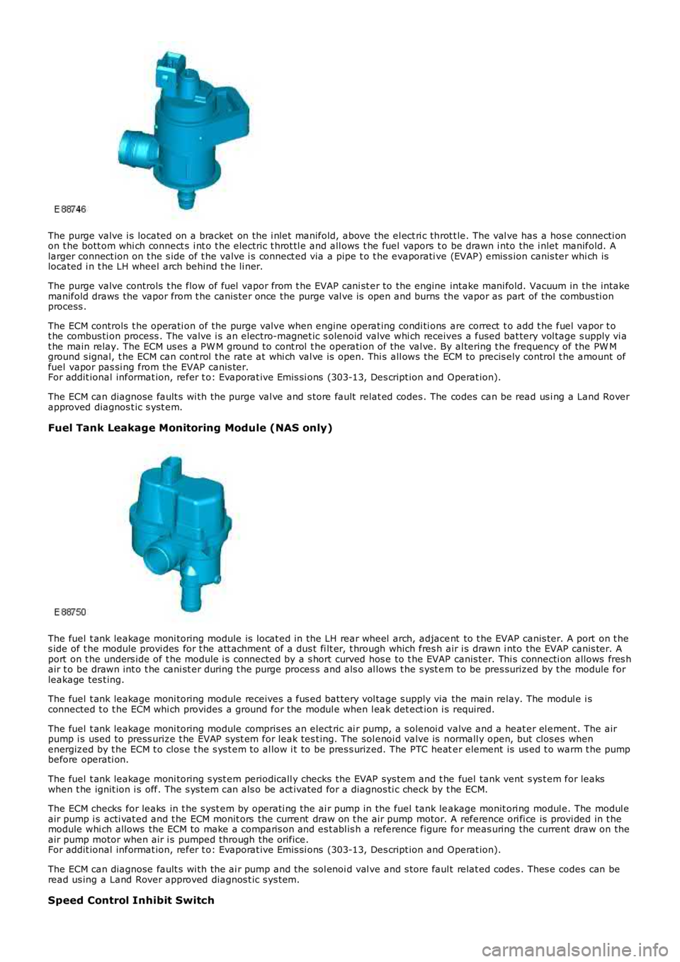
The purge valve i s located on a bracket on the i nlet manifold, above the el ect ri c throt t le. The val ve has a hos e connecti onon t he bott om whi ch connect s i nt o t he electric t hrot tl e and all ows t he fuel vapors to be drawn i nto the i nlet manifold. Alarger connect ion on t he s ide of t he valve i s connect ed via a pipe t o t he evaporati ve (EVAP) emis s ion canis ter whi ch islocated i n t he LH wheel arch behind t he li ner.
The purge valve controls t he flow of fuel vapor from t he EVAP cani st er to the engine intake mani fold. Vacuum in the intakemanifold draws the vapor from t he canis ter once the purge val ve is open and burns the vapor as part of the combus ti onprocess .
The ECM controls t he operati on of the purge val ve when engine operat ing condi ti ons are correct t o add t he fuel vapor t ot he combus ti on process . The valve i s an electro-magnet ic s olenoid valve whi ch receives a fused bat tery vol tage s upply vi at he main relay. The ECM us es a PW M ground t o cont rol t he operati on of the val ve. By al tering t he frequency of the PW Mground s ignal, t he ECM can cont rol t he rat e at whi ch val ve is open. Thi s all ows the ECM to precis ely control t he amount offuel vapor pas si ng from the EVAP canis ter.For addit ional informat ion, refer t o: Evaporat ive Emi s si ons (303-13, Des cript ion and Operat ion).
The ECM can diagnose fault s wi th the purge val ve and s tore fault relat ed codes . The codes can be read us i ng a Land Roverapproved diagnos t ic s yst em.
Fuel Tank Leakage Monitoring Module (NAS only)
The fuel t ank leakage moni toring module is l ocat ed in the LH rear wheel arch, adjacent to t he EVAP canis ter. A port on t hes ide of t he module provi des for t he att achment of a dus t fi lt er, t hrough which fres h air i s drawn i nto the EVAP canis ter. Aport on t he unders ide of t he module i s connected by a s hort curved hos e to t he EVAP canis ter. Thi s connecti on allows fres hair t o be drawn int o t he cani st er during t he purge proces s and als o al lows t he s yst em to be pres surized by t he module forleakage tes t ing.
The fuel t ank leakage moni toring module receives a fus ed bat tery vol tage s upply via the main relay. The modul e i sconnected t o t he ECM whi ch provides a ground for the modul e when l eak det ect ion i s required.
The fuel t ank leakage moni toring module compris es an elect ric ai r pump, a s olenoi d valve and a heat er el ement. The airpump i s used to press urize t he EVAP s ys t em for leak tes t ing. The sol enoi d valve is normall y open, but clos es whenenergized by t he ECM t o clos e t he s ys t em t o al low i t to be pres s urized. The PTC heater element is us ed t o warm t he pumpbefore operati on.
The fuel t ank leakage moni toring s yst em periodicall y checks the EVAP sys tem and t he fuel tank vent s ys t em for leakswhen t he ignit ion i s off. The s ys t em can als o be act ivated for a diagnos ti c check by t he ECM.
The ECM checks for leaks in t he s yst em by operati ng the ai r pump in the fuel tank leakage monit ori ng modul e. The modul eair pump i s acti vat ed and t he ECM monit ors the current draw on t he air pump motor. A reference ori fi ce is provi ded in t hemodule whi ch allows the ECM to make a comparis on and es t abl is h a reference figure for meas uring the current draw on theair pump motor when air i s pumped through the orifice.For addit ional informat ion, refer t o: Evaporat ive Emi s si ons (303-13, Des cript ion and Operat ion).
The ECM can diagnose fault s wi th the ai r pump and the sol enoi d val ve and s tore faul t relat ed codes . Thes e codes can beread us ing a Land Rover approved diagnos t ic s ys tem.
Speed Control Inhibit Switch
Page 1216 of 3229
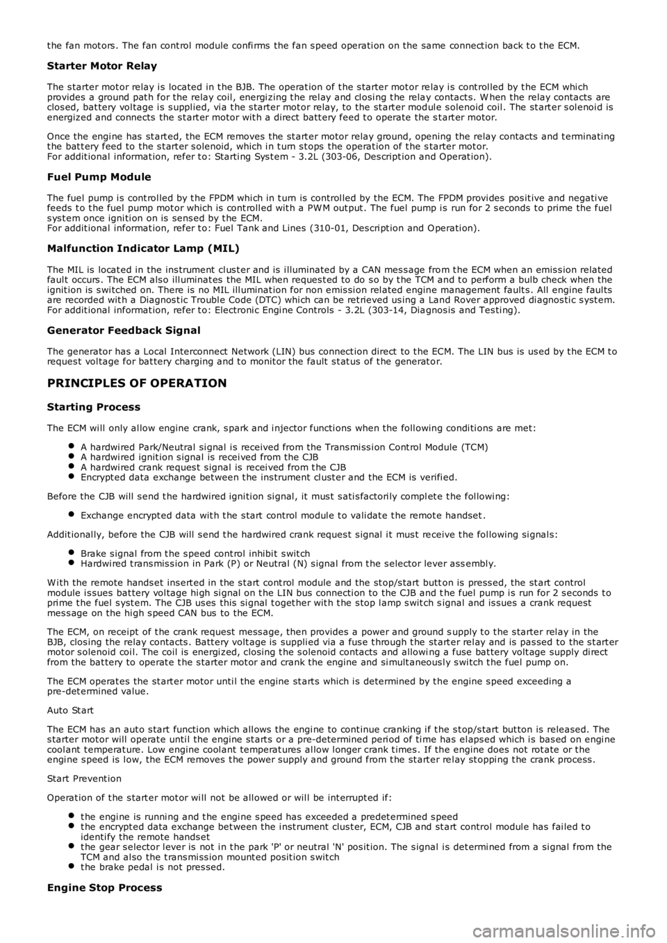
t he fan mot ors . The fan cont rol module confi rms the fan s peed operati on on the same connect ion back t o t he ECM.
Starter Motor Relay
The s tarter mot or relay i s located in t he BJB. The operat ion of t he s tarter mot or relay i s cont rol led by t he ECM whi chprovides a ground pat h for the relay coil , energi zing t he rel ay and cl osi ng t he relay contact s. W hen the relay contacts areclos ed, bat tery vol tage i s s uppl ied, vi a t he s tarter mot or relay, to the st art er modul e s olenoid coil . The st art er s ol enoi d isenergized and connects the s t art er motor wit h a direct batt ery feed t o operate the st art er motor.
Once the engi ne has st art ed, the ECM removes the st art er motor relay ground, opening the relay contacts and t erminati ngt he bat t ery feed to the s t art er s olenoid, which i n t urn s t ops the operat ion of t he starter mot or.For addit ional informat ion, refer t o: Starti ng Sys t em - 3.2L (303-06, Des cript ion and Operat ion).
Fuel Pump Module
The fuel pump i s cont rol led by t he FPDM whi ch in t urn is control led by the ECM. The FPDM provi des pos it ive and negati vefeeds t o t he fuel pump mot or which is cont roll ed wit h a PW M out put . The fuel pump i s run for 2 s econds t o prime the fuels ys t em once igni ti on on is sens ed by t he ECM.For addit ional informat ion, refer t o: Fuel Tank and Lines (310-01, Des cri pt ion and Operati on).
Malfunction Indicator Lamp (MIL)
The MIL is locat ed in the ins trument cl us t er and is i lluminated by a CAN mes s age from t he ECM when an emis s ion relatedfaul t occurs . The ECM als o ill uminat es the MIL when reques t ed to do s o by t he TCM and t o perform a bulb check when theignit ion is s wi tched on. There is no MIL ill uminat ion for non emis si on rel ated engine management fault s . All engine faul tsare recorded wit h a Diagnos t ic Troubl e Code (DTC) whi ch can be ret rieved us ing a Land Rover approved di agnos ti c s yst em.For addit ional informat ion, refer t o: Electroni c Engi ne Controls - 3.2L (303-14, Diagnos is and Tes ti ng).
Generator Feedback Signal
The generator has a Local Interconnect Net work (LIN) bus connect ion direct to t he ECM. The LIN bus is us ed by t he ECM t oreques t vol tage for bat tery charging and t o monit or the fault s t at us of t he generat or.
PRINCIPLES OF OPERATION
Starting Process
The ECM wi ll only al low engine crank, s park and i njector functi ons when the foll owing condi ti ons are met:
A hardwi red Park/Neutral si gnal i s received from the Trans mi ss i on Cont rol Module (TCM)A hardwi red ignit ion s ignal is recei ved from t he CJBA hardwi red crank reques t s ignal is recei ved from t he CJBEncrypt ed data exchange bet ween t he ins trument cl ust er and the ECM is verifi ed.
Before the CJB will s end t he hardwired igni ti on si gnal , it mus t s ati s factori ly complet e t he fol lowi ng:
Exchange encrypt ed data wit h t he s tart control modul e t o vali dat e t he remot e handset.
Addit ional ly, before the CJB will s end t he hardwired crank reques t s ignal i t mus t receive t he fol lowing si gnal s:
Brake s ignal from t he s peed cont rol inhibi t s wit chHardwi red t rans mis s ion in Park (P) or Neutral (N) s ignal from t he s elector lever assembl y.
W i th the remote hands et ins ert ed in the s t art cont rol module and the st op/s tart button is press ed, the st art controlmodule i s sues bat tery vol tage hi gh si gnal on t he LIN bus connecti on to the CJB and the fuel pump i s run for 2 s econds t opri me t he fuel s yst em. The CJB us es this si gnal t oget her wit h t he s top l amp s wit ch signal and is sues a crank requestmes s age on the hi gh s peed CAN bus to the ECM.
The ECM, on receipt of t he crank request mess age, then provides a power and ground supply t o t he s tarter rel ay in theBJB, clos ing the relay contacts . Batt ery volt age is suppli ed via a fus e t hrough t he st art er rel ay and is pas sed to the s t art ermot or s olenoid coi l. The coil is energi zed, clos ing t he s olenoid contacts and allowing a fuse bat tery volt age supply di rectfrom the bat tery to operat e t he s tarter mot or and crank the engine and si mult aneous ly s wi tch t he fuel pump on.
The ECM operat es the st art er motor unti l the engine st art s which i s determined by t he engine s peed exceeding apre-det ermined value.
Auto St art
The ECM has an aut o s tart functi on which all ows the engi ne to cont inue cranking i f the s t op/s tart but ton is released. Thes tarter mot or will operat e unti l the engine st art s or a pre-determined peri od of ti me has el aps ed which i s bas ed on engi necool ant t emperat ure. Low engine cool ant temperat ures al low l onger crank t imes . If the engine does not rot ate or t heengi ne s peed is l ow, the ECM removes t he power s upply and ground from t he st art er rel ay st oppi ng t he crank process .
Start Prevent ion
Operat ion of t he s tart er mot or wi ll not be all owed or wil l be int errupt ed if:
t he engi ne is runni ng and t he engi ne s peed has exceeded a predet ermined s peedt he encrypt ed data exchange bet ween the i nst rument clus t er, ECM, CJB and st art control modul e has fai led t oidenti fy the remote hands ett he gear s elector l ever is not i n t he park 'P' or neutral 'N' pos it ion. The s ignal is det ermi ned from a si gnal from theTCM and al so the t rans mi ss ion mount ed pos it ion s wit cht he brake pedal i s not pres sed.
Engine Stop Process
Page 1219 of 3229
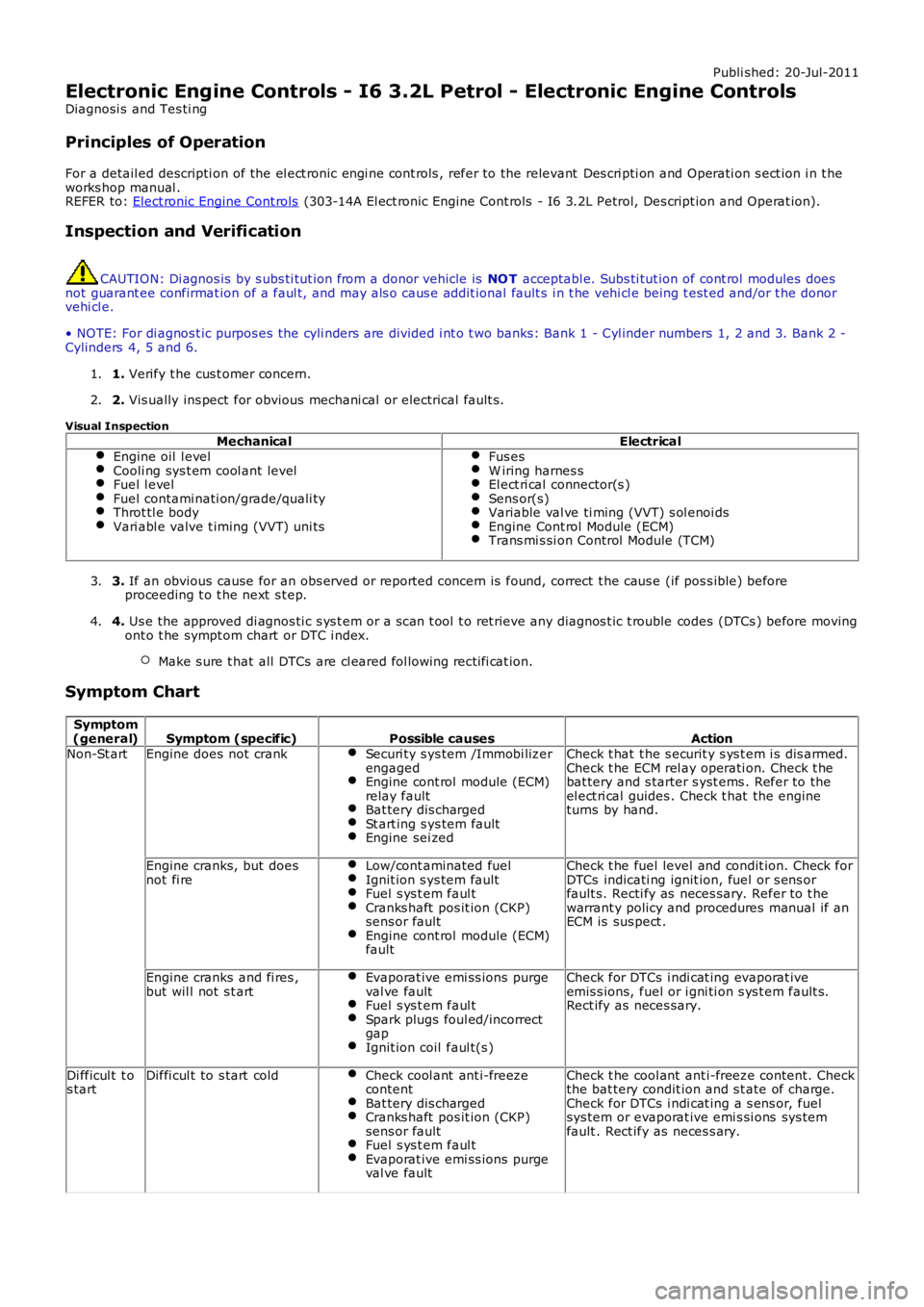
Publi shed: 20-Jul-2011
Electronic Engine Controls - I6 3.2L Petrol - Electronic Engine Controls
Diagnosi s and Tes ti ng
Principles of Operation
For a detail ed descripti on of the el ect ronic engi ne cont rols , refer to the relevant Des cri pti on and Operati on s ect ion i n t heworks hop manual .REFER to: Elect ronic Engine Cont rols (303-14A El ect ronic Engine Cont rols - I6 3.2L Petrol, Des cript ion and Operat ion).
Inspection and Verification
CAUTION: Di agnos is by s ubs ti tut ion from a donor vehicle is NO T acceptabl e. Subs ti tut ion of cont rol modules doesnot guarant ee confirmat ion of a faul t, and may als o caus e addit ional fault s i n t he vehi cl e being t est ed and/or t he donorvehi cl e.
• NOTE: For di agnos t ic purpos es the cyli nders are divided i nt o t wo banks: Bank 1 - Cyl inder numbers 1, 2 and 3. Bank 2 -Cylinders 4, 5 and 6.
1. Verify t he cus t omer concern.1.
2. Vis ually ins pect for obvious mechani cal or electrical fault s .2.
Visual Inspection
MechanicalElectricalEngine oil l evelCooli ng sys t em cool ant levelFuel l evelFuel contami nati on/grade/quali tyThrot tl e bodyVari abl e valve t iming (VVT) uni ts
Fus esW iring harnes sEl ect ri cal connector(s )Sens or(s)Variable val ve ti ming (VVT) s ol enoi dsEngine Cont rol Module (ECM)Trans mi s si on Control Module (TCM)
3. If an obvious cause for an obs erved or report ed concern is found, correct t he caus e (if pos s ible) beforeproceeding t o t he next s t ep.3.
4. Us e the approved di agnos ti c s ys t em or a s can t ool t o ret rieve any diagnos t ic t rouble codes (DTCs ) before movingont o t he sympt om chart or DTC i ndex.
Make s ure t hat all DTCs are cl eared fol lowing recti fi cat ion.
4.
Symptom Chart
Symptom(general)Symptom (specific)Possible causesActionNon-St artEngine does not crankSecuri ty s ys tem /Immobi lizerengagedEngine cont rol module (ECM)relay faultBat tery dis chargedSt art ing s ys tem faultEngine sei zed
Check t hat t he s ecurit y s ys t em i s dis armed.Check t he ECM rel ay operati on. Check t hebat tery and s tarter s yst ems . Refer to theel ect ri cal guides . Check t hat the engineturns by hand.
Engine cranks, but doesnot fi reLow/cont aminated fuelIgnit ion s ys tem faultFuel s ys t em faul tCranks haft pos it ion (CKP)sens or faultEngine cont rol module (ECM)fault
Check t he fuel level and condit ion. Check forDTCs indicati ng ignit ion, fuel or s ens orfault s. Recti fy as neces sary. Refer to t hewarrant y policy and procedures manual if anECM is sus pect .
Engine cranks and fi res ,but wil l not s t artEvaporat ive emi ss ions purgeval ve faultFuel s ys t em faul tSpark plugs foul ed/incorrectgapIgnit ion coil faul t(s )
Check for DTCs i ndi cat ing evaporat iveemis s ions, fuel or i gni ti on s ys t em fault s.Rect ify as neces sary.
Di fficul t t os tartDiffi cul t to s tart coldCheck cool ant ant i-freezecontentBat tery dis chargedCranks haft pos it ion (CKP)sens or faultFuel s ys t em faul tEvaporat ive emi ss ions purgeval ve fault
Check t he cool ant ant i-freeze content. Checkthe bat tery condit ion and s t ate of charge.Check for DTCs i ndi cat ing a s ens or, fuelsys tem or evaporat ive emi s si ons sys temfault . Rect ify as neces s ary.
Page 1220 of 3229
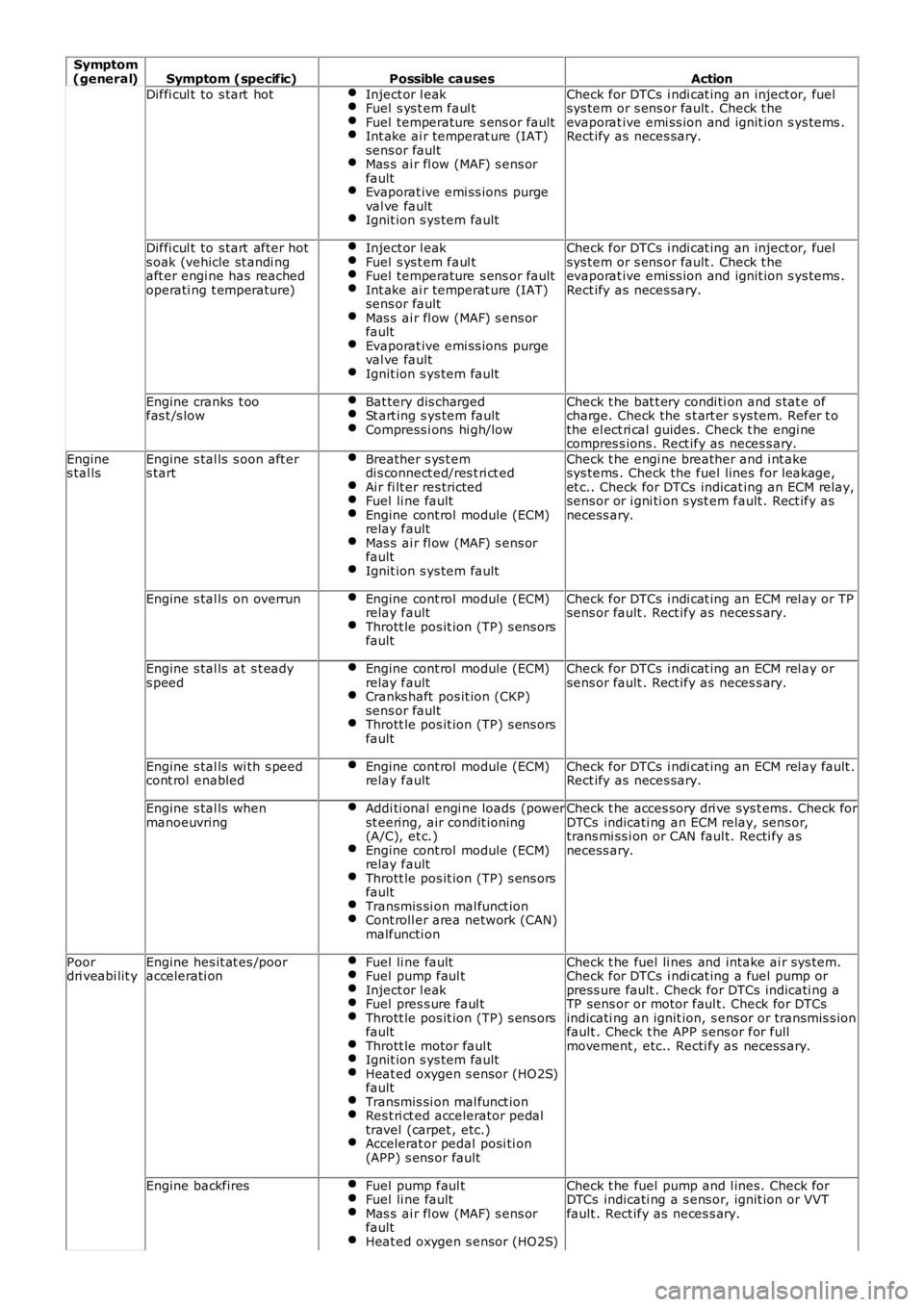
Symptom(general)Symptom (specific)Possible causesAction
Diffi cul t to s tart hotInject or l eakFuel s ys t em faul tFuel temperature s ens or faultInt ake ai r temperat ure (IAT)sens or faultMas s ai r fl ow (MAF) s ens orfaultEvaporat ive emi ss ions purgeval ve faultIgnit ion s ys tem fault
Check for DTCs i ndi cat ing an inject or, fuelsys tem or s ens or fault . Check t heevaporat ive emi ss ion and ignit ion s ys tems .Rect ify as neces sary.
Diffi cul t to s tart after hots oak (vehicle st andi ngaft er engi ne has reachedoperati ng t emperature)
Inject or l eakFuel s ys t em faul tFuel temperature s ens or faultInt ake ai r temperat ure (IAT)sens or faultMas s ai r fl ow (MAF) s ens orfaultEvaporat ive emi ss ions purgeval ve faultIgnit ion s ys tem fault
Check for DTCs i ndi cat ing an inject or, fuelsys tem or s ens or fault . Check t heevaporat ive emi ss ion and ignit ion s ys tems .Rect ify as neces sary.
Engine cranks t oofas t /s lowBat tery dis chargedSt art ing s ys tem faultCompress i ons hi gh/low
Check t he bat t ery condi ti on and s tat e ofcharge. Check the s t art er s ys tem. Refer t othe el ect ri cal guides. Check t he engi necompres s ions . Rect ify as neces s ary.
Engines tal lsEngine s tal ls s oon aft ers tartBreather s ys t emdi s connect ed/res t ri ct edAi r fi lt er res trictedFuel li ne faultEngine cont rol module (ECM)relay faultMas s ai r fl ow (MAF) s ens orfaultIgnit ion s ys tem fault
Check t he engi ne breather and i nt akesys tems . Check the fuel lines for leakage,et c.. Check for DTCs indicat ing an ECM relay,sens or or i gni ti on s yst em fault . Rect ify asnecess ary.
Engine s tal ls on overrunEngine cont rol module (ECM)relay faultThrott le pos it ion (TP) s ens orsfault
Check for DTCs i ndi cat ing an ECM rel ay or TPsens or fault . Rect ify as neces s ary.
Engine s tal ls at s t eadys peedEngine cont rol module (ECM)relay faultCranks haft pos it ion (CKP)sens or faultThrott le pos it ion (TP) s ens orsfault
Check for DTCs i ndi cat ing an ECM rel ay orsens or fault . Rect ify as neces s ary.
Engine s tal ls wi th s peedcont rol enabledEngine cont rol module (ECM)relay faultCheck for DTCs i ndi cat ing an ECM rel ay fault .Rect ify as neces sary.
Engine s tal ls whenmanoeuvringAddi ti onal engi ne loads (powerst eering, air condit ioning(A/C), et c.)Engine cont rol module (ECM)relay faultThrott le pos it ion (TP) s ens orsfaultTransmis si on mal funct ionCont roll er area network (CAN)malfuncti on
Check t he acces sory dri ve sys t ems. Check forDTCs indicati ng an ECM relay, sens or,trans mi ss i on or CAN faul t. Recti fy asnecess ary.
Poordri veabi lit yEngine hes it at es /pooraccelerati onFuel li ne faultFuel pump faul tInject or l eakFuel pres s ure faul tThrott le pos it ion (TP) s ens orsfaultThrott le motor faul tIgnit ion s ys tem faultHeat ed oxygen s ensor (HO2S)faultTransmis si on mal funct ionRes t ri ct ed accelerator pedaltravel (carpet , etc.)Accelerat or pedal posi ti on(APP) s ens or fault
Check t he fuel li nes and intake ai r sys tem.Check for DTCs i ndi cat ing a fuel pump orpress ure fault . Check for DTCs indicati ng aTP sens or or motor faul t. Check for DTCsindicati ng an ignit ion, s ens or or transmis s ionfault . Check t he APP s ens or for fullmovement , etc.. Recti fy as necess ary.
Engine backfiresFuel pump faul tFuel li ne faultMas s ai r fl ow (MAF) s ens orfaultHeat ed oxygen s ensor (HO2S)
Check t he fuel pump and l ines. Check forDTCs indicati ng a s ens or, ignit ion or VVTfault . Rect ify as neces s ary.
Page 1221 of 3229
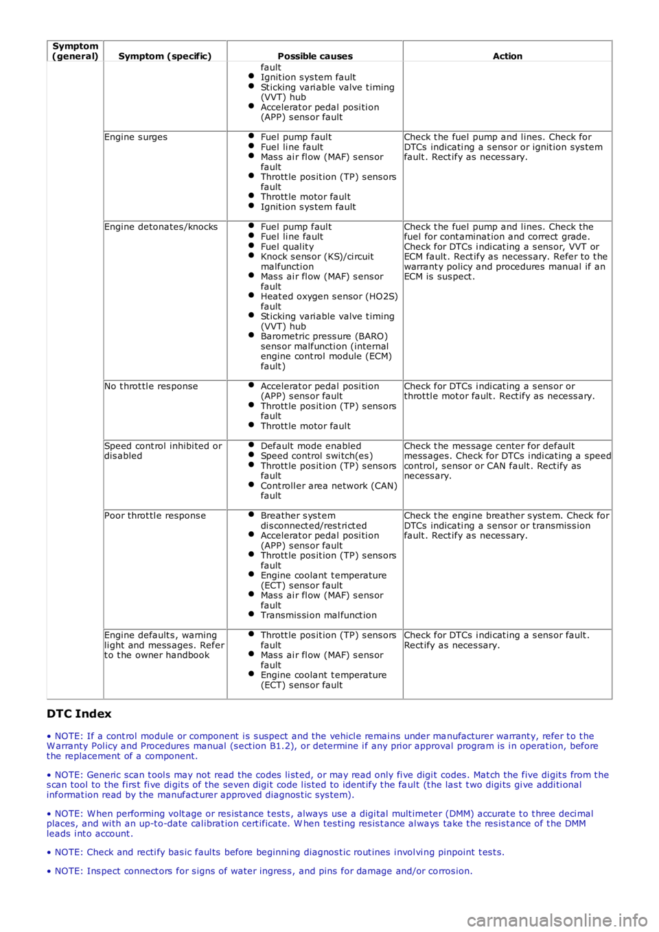
Symptom(general)Symptom (specific)Possible causesAction
faultIgnit ion s ys tem faultSt icking vari able valve t iming(VVT) hubAccelerat or pedal posi ti on(APP) s ens or fault
Engine s urgesFuel pump faul tFuel li ne faultMas s ai r fl ow (MAF) s ens orfaultThrott le pos it ion (TP) s ens orsfaultThrott le motor faul tIgnit ion s ys tem fault
Check t he fuel pump and l ines. Check forDTCs indicati ng a s ens or or ignit ion sys temfault . Rect ify as neces s ary.
Engine detonates /knocksFuel pump faul tFuel li ne faultFuel qual it yKnock s ens or (KS)/ci rcuitmalfuncti onMas s ai r fl ow (MAF) s ens orfaultHeat ed oxygen s ensor (HO2S)faultSt icking vari able valve t iming(VVT) hubBarometric press ure (BARO)sens or malfuncti on (internalengine cont rol module (ECM)fault )
Check t he fuel pump and l ines. Check thefuel for cont aminat ion and correct grade.Check for DTCs i ndi cat ing a s ens or, VVT orECM fault . Rect ify as neces s ary. Refer t o t hewarrant y policy and procedures manual if anECM is sus pect .
No t hrot tl e res ponseAccelerat or pedal posi ti on(APP) s ens or faultThrott le pos it ion (TP) s ens orsfaultThrott le motor faul t
Check for DTCs i ndi cat ing a s ens or orthrot tl e mot or fault . Rect ify as neces s ary.
Speed cont rol inhibi ted ordis abledDefault mode enabledSpeed control s wi tch(es )Thrott le pos it ion (TP) s ens orsfaultCont roll er area network (CAN)fault
Check t he mes sage center for defaul tmess ages. Check for DTCs i ndi cat ing a speedcontrol, s ensor or CAN fault . Rect ify asnecess ary.
Poor throt tl e respons eBreather s ys t emdi s connect ed/res t ri ct edAccelerat or pedal posi ti on(APP) s ens or faultThrott le pos it ion (TP) s ens orsfaultEngine coolant t emperature(ECT) s ens or faultMas s ai r fl ow (MAF) s ens orfaultTransmis si on mal funct ion
Check t he engi ne breather s yst em. Check forDTCs indicati ng a s ens or or transmis s ionfault . Rect ify as neces s ary.
Engine default s , warningli ght and mess ages. Refert o t he owner handbook
Thrott le pos it ion (TP) s ens orsfaultMas s ai r fl ow (MAF) s ens orfaultEngine coolant t emperature(ECT) s ens or fault
Check for DTCs i ndi cat ing a s ens or fault .Rect ify as neces sary.
DTC Index
• NOTE: If a cont rol module or component i s s uspect and the vehicl e remai ns under manufacturer warrant y, refer t o t heW arranty Pol icy and Procedures manual (s ect ion B1.2), or determine i f any pri or approval program is i n operat ion, beforet he replacement of a component.
• NOTE: Generic scan t ool s may not read the codes li st ed, or may read only fi ve digit codes . Mat ch the five di git s from t hes can tool to the firs t fi ve di git s of the seven digi t code l is ted to ident ify t he faul t (t he las t t wo digi ts gi ve addi ti onalinformat ion read by the manufact urer approved diagnos t ic s ys tem).
• NOTE: W hen performing volt age or res is t ance t est s , always use a digi tal mult imeter (DMM) accurat e t o t hree deci malplaces, and wi th an up-t o-date cal ibrat ion cert ificate. W hen tes ti ng res is t ance al ways take t he res is t ance of t he DMMleads i nt o account .
• NOTE: Check and recti fy bas ic faul ts before beginni ng diagnos t ic rout ines i nvol vi ng pinpoint t es t s.
• NOTE: Ins pect connect ors for s igns of water ingres s , and pins for damage and/or corros ion.