2006 LAND ROVER FRELANDER 2 ECO mode
[x] Cancel search: ECO modePage 2179 of 3229
and adopt ed as t he current pos it ions. This wil l al low the relat ive memory posi ti ons to be ret ained wit hout any need t o
recali brate the power s eat modul e.
The power seat module is able to be 'flas hed' for s ervice updates or i nterrogat ed us ing t he Land Rover approved diagnost ic
equi pment.
Up t o 3 di fferent s eat pos it ions are abl e t o be s t ored i n the power s eat modul e. Sea t pos it ions are st ored in memory by
pres s ing t he memory butt on ( M), and t hen 1 of t he 3 memory s tore butt ons ( 1, 2, 3) wi thi n 5 s econds . The memory
butt ons are l ocat ed on t he s wit ch pack. The swit ch pack memory butt ons allow the dri ver t o cont rol t he memory st orage
and recall operat ions for t he s eat and ext erior mi rrors . The s wit ch pack but tons are non-lat chi ng, moment ary act ion
s wit ches .
On vehicles i nst all ed wit h a hi gh-li ne ins t rument clus ter and t he ignit ion s wi tched on, the s eat posi ti on memory s tore
commands are di spl ayed i n t he mes sage center and a si ngl e chime is s ounded to confi r m t he new s eat pos it ion i s s aved.
• NOTE: Low-l ine i nst rument clus ters are not i nst all ed to vehi cl es equi pped wit h a m emory s eat sys t em.
For addit ional informat ion, refer t o: Ins t rument Clus ter (413-01 Inst rument Cl us t er, Des cript ion and Operat ion) /
Informat ion and Mes s age Cent er (413-08 Informat ion and Mes s age Cent er, Des cript ion and Operat ion).
The power seat module provi des the foll owing driver sel ect abl e functi ons: Seat and ext erior mirror memory recall Immediat e s eat adjus t ment.
For furt her operat ing det ail s of the driver sel ect abl e funct ions, refer t o t he s ect i
on 'Principles of Operat ion'.
The act ivi ty of t he s eat is automat icall y monit ored by t he power s eat module. The mo dule wil l react to motors that are not
functi oni ng correct ly t o an operat ion reques t , and will al so aim to reduce power con sumpt ion during peri ods of i nact ivit y.
The power seat module provi des the foll owing automat ic moni toring funct ions : Stal l det ect ion mode Sleep mode
Batt ery moni tor mode.
For furt her operat ing det ail s of the aut omati c monit oring funct ions , refer t o t he s e
ct ion 'Pri nci pl es of Operati on'.
Calibration of Power Seat Module
If the power s eat modul e is replaced in servi ce, t he repl acement module must be cali brat ed usi ng t he Land Rover approved
diagnost ic equipment . The cal ibrat ion routi ne is necess ary for t he power s eat module t o reset t he s eat dat um values .
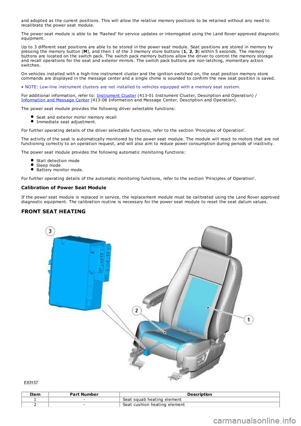
FRONT SEAT HEATING Item
Part Number Description
1 -Seat s quab heat ing el ement
2 -Seat cus hi on heat ing el ement
Page 2185 of 3229
6
-St art control modul e
PRINCIPLES OF OPERATION
Front Power Operated Non-Memory Seats
The dri ver's non-memory s eat wil l operate i n all i gni ti on power modes . The pas senger non-memory seat wi ll only operat e
when t he ignit ion i s i n power mode 6 (Ignit ion).
Power for front pas s enger s eat operat ion is s upplied from t he AJB via a pas s enger s e at power relay t o t he pas s enger s eat
cont rol s wit ch pack. Power for t he driver's s eat operat ion is s upplied di rectl y from the AJB t o t he dri ver's s eat cont rol
s wit ch pack. The front pas s enger and dri ver s eat power suppli es are controlled by th e CJB. The s eat s wi tch pack direct s the
volt age to t he relevant s eat adjus tment mot or when a s eat control swit ch is pres s ed. Two pins wi thin each of t he s eat
s wit ch packs cont rol t he s eat motors. Bot h pins are normal ly connect ed to ground.
The dri ver and pas senger s wit ch packs are al s o connected i n circui t wit h a bat tery-s aver t imer relay t hat i s located in, and
cont rol led by t he CJB. The bat tery-s aver t imer relay all ows operati on of the driver and pas s enger s eat cont rols for 10
mi nut es aft er the engine is s wit ched off, and the i gni ti on is then s elected t o an ap propriat e power mode. The 10 minute
t imer is res et if t he appropriat e i gni ti on power mode is retai ned and the driver's d oor i s opened or clos ed. The driver and
pass enger s eat operati on is inhibit ed i mmediat el y fol lowi ng cent ral locking of t he v ehi cl e.
Operat ing a seat mot or control swit ch appli es volt age to one of t he pins whi le t he o t her pi n remai ns connect ed t o ground.
Operat ing t he s eat motor cont rol s wit ch in the oppos it e direct ion reverses the power and ground connecti ons to the mot or,
all owing t he mot or pi ni on t o rot ate in t he oppos i te di recti on. In t he event t hat a m ot or sei zes or s t icks , an i nternal
t hermal cut -out s wit ch wil l trip to remove volt age from t he mot or.
Driver's Power Operated Memory Seat
The dri ver's memory s eat wil l operat e when t he i gni ti on is in power modes 4 (Acces so ry) and 6 (Ignit ion), and wi ll not
operate during power mode 9 (Engine crank).
Power for the driver's memory s eat operat ion i s s uppl ied di rectl y from t he AJB t o t h e power s eat module. The memory s eat
s wit ch pack i s connected t o t he power seat module that cont rol s t he operati on and me mory pos it ion of t he i ndi vi dual s eat
mot ors . The power s eat module i s connected on the medi um s peed CAN bus t o t he CJB an d the front LH and RH door
cont rol modules .
The power seat module is als o connect ed in ci rcuit wi th a batt ery-saver ti mer rel ay that is locat ed wi thin, and controlled by
t he CJB. The batt ery-saver ti mer rel ay allows operat ion of t he s eat cont rols for 10 mi nut es aft er the engine is s wi tched off,
and t he ignit ion i s t hen sel ect ed to an appropri at e power mode. The 10 minut e t imer i s res et if t he appropri at e i gni ti on
power mode is retai ned and the driver's door i s opened or clos ed. The driver's s eat operat ion is i nhi bit ed immedi ately
fol lowing cent ral locki ng of the vehicl e.
Reques t s for memory exterior mirror movements for a memory recal l are t rans mit ted on the medi um s peed CAN bus by t he
power seat module to t he front door control modul es. The front door cont rol modules direct ly control the memory s t ore and
recall pos it ions for t he memory ext eri or mirrors.
For addit ional informat ion, refer t o: Rear Vi ew Mi rrors (501-09 Rear View Mirrors , Des cript ion and Operat ion).
Power Seat Mod ule
The power seat module features driver s electable funct ions , and aut omat ic monit ori ng functi ons .
Driver Selectable Functions
Seat and ext erior mirror memory recall Immediat e s eat adjus t ment.
Seat and exterior mirror memory recall function
The memory recall functi on s ets t he driver's seat t o a s t ored pos it ion, and is acti v at ed when a swi tch pack memory
posi ti on butt on is pres sed. W hen memory recal l i s i ni ti ated, only 2 seat adjus tment mot ors wil l operat e at any one t ime to
li mit the overall current cons umpti on. To furt her minimize t he current l oad as the m otors energize, the i nit iati on of each of
t he 2 operati ng mot ors i s phas ed wi th a 10 mill is econd del ay. The cushi on s lide and backres t wil l move fi rs t , foll owed by
t he cus hion height .
As s oon as t he seat s wit ch pack memory pos it ion but ton is pres s ed, a mes sage i s t ran s mit ted by the power s eat modul e
on t he medium s peed CAN bus to the front door control modul es. The door cont rol modu les t hen act ivat e t he memory
recall pos it ions for t he exteri or mirrors. The i nst rument clus t er mess age cent er wil l di s pl ay memory recall mes s ages when
a memory recall i s acti vat ed.
The memory recall functi on operates wit h 2 s eparate modes; t he operat ion of each mod e is dependant on t he vehicle
s tat us when the seat memory posi ti on butt on is pres sed.
Memory recall operati ng modes:
One-t ouch mode Proport ional mode.
One-Touch Mode
W hen t he vehicle i s s tat ionary and a s wit ch pack memory pos it ion butt on i s pres sed, t he memory recall functi on wil l
operate in 'one-touch' mode. One t ouch mode all ows the seat and exterior mirrors t o immediatel y move t o t he request ed
s tored memory pos i ti on.
If a s eat adjus t ment or memory pos it ion but ton i s operat ed during memory recal l 'one -t ouch' mode, t he current memory
recall wi ll be cancell ed and t he seat (and ext eri or mirrors via t he medium s peed CAN bus) wi ll i mmediat el y s top movi ng.
The s eat will t hen commence movi ng in the di recti on that corresponds to the press ed s wi tch.
Page 2186 of 3229
Memory recall is al s o immedi atel y cancelled if t he vehi cl e is driven from t he st ati o nary pos it ion before t he seat has
reached the reques t ed memory pos i ti on.
Proport ional Mode
If the vehicle is already in moti on when the swi tch pack memory posi ti on butt on is p ress ed, the memory recal l functi on wil l
operate in 'proport ional' mode. Proport ional mode recal ls the s eat (and ext erior mi r ror) pos it ion for the durat ion t hat the
memory s wit ch is held in the pres s ed s tat e. W hen t he memory pos i ti on but t on is relea s ed the memory recal l wil l
immediatel y s top, unles s the seat has already reached t he int ended memory pos it ion.
In order to reach t he int ended s t ored memory posi ti on whil e t he vehi cl e is moving, t he memory pos it ion but ton mus t not
be rel eased unt il all s eat, and exterior mi rror movement s are compl et e.
Immediate seat adjustment function
The immediate adjust ment functi on is act ivated when a s wit ch pack s eat posi ti on s wit ch (recl ine, s lide or height ) is
operated.
Pres s ing any of t he seat adjus t ment swi tches wil l init iat e t he corres pondi ng direct i on mot or to move t he seat i n t hat
direct ion, unti l t he s wit ch is releas ed. Onl y 2 s eat mot ors wi ll operate at any one ti me.
Automatic Monitoring Functions
The power seat module aut omati c monit ori ng functi ons are detai led as follows :
Stal l det ect ion mode Sleep mode
Batt ery moni tor mode.
Stall detection mode
A s eat mot or i s deemed t o have st all ed if t here i s no change i n t he input t hat i s re ceived from the corres ponding feedback
s ens or for 200 mill is econds , while that axis i s being driven.
If a s tall condit ion i s det ected by t he power seat module then t he dri ve to that axi s i s cancell ed for t he remai nder of t hat
memory operati on (memory recal l), or unt il t he s wit ch is re-s elected (immediate s eat adjus t ment).
For al l seat mot or manual movements during an immedi at e s eat adjus tment funct ion, wh en a mot or is driven and a s t al l
occurs the power s eat modul e records and s t ores t he s tal l pos it ion (s oft s t op) t hat the s t all occurred. If movement occurs
beyond t he s tored s oft s top st all pos it ion, then t he s tal l pos it ion i s eras ed from t he power s eat modul e memory. Thi s wil l
always all ow movement past a previousl y recorded s t all posi ti on once movement has be en regi st ered beyond that pos it ion
(i.e. by press ing the s wi tch for longer t han 2 s econds ).
If the mot or movement has s t opped due t o a motor s tal l (s eat obs t ructi on for example ), once t he obst ruct ion i s cl eared
t hen that axi s may be act ivated again to move pas t t he new s oft s t op s tal l pos it ion by re-s elect ing t he appropriat e s wit ch
and pres s ing for longer t han 2 s econds . If t he s wit ch is not operat ed to move t he se at pas t the new soft s top pos it ion,
t hi s posi ti on wi ll remai n s tored in the power s eat modul e memory as t he full axis mo vement .
If motor movement has st opped due to los s of sens or feedback (s ens or or wiring failu re) then t hat axi s may be acti vat ed
agai n t o move pas t the st all posi ti on by re-s electi ng the appropriate s wit ch and pre s si ng for l onger t han 2 s econds. This
all ows cont rol of the motor t o be mai nt ained i f sens or feedback i s los t .
Upon re-s el ect ion of movement , if s ens or puls es are det ect ed t hen the mot or wil l con t inue t o be dri ven unt il t he s wit ch is
rel eas ed or another s tall condit ion i s det ected. If s ens or feedback is not det ect ed then t he mot or is only driven for 0.5
s econd and t hen s tops , unt il t he s wit ch is releas ed and then pres s ed again for longe r t han 2 s econds , when a furt her 0.5
s econd of acti vat ion i s permi tt ed and s o on. This i s known as 'i nch mode'.
If there is a fail ure wit h the medium speed CAN bus net work, the seat wi ll operate i n 'inch mode'.
• NOTE: For di agnos t ic purpos es, an i ndicat ion of medi um s peed CAN bus dis connecti on is apparent i f the s eat is operat ing
in 'inch mode' and eit her t he s eat cont rol module, CJB or door cont rol modules are n ot s hown connect ed t o t he medium
s peed CAN bus.
Sleep mode
The power seat module features a s leep mode t o reduce power cons umpt ion t o t he requi red mi ni mum.
If the power s eat modul e is bei ng prevent ed from ent eri ng s leep mode due t o mot or mo vement , memory recall or s wit ch
pack operat ion, t hen the modul e wil l ent er s leep mode when t he current funct ion has t ermi nat ed.
• NOTE: In t he cas e of a memory recal l, all memory recall operat ions are carri ed out before t he power seat module ent ers
s leep mode, and not jus t the current motor movement.
The power seat module will exit s l eep mode when any CAN bus acti vi ty is det ect ed.
Battery monitor mode
The power seat module moni tors t he input power s upply t o make s ure there is suffi ci e nt bat tery vol tage avail abl e for
engi ne cranking. If t he batt ery volt age drops below 10.5 volt s , then t he power seat module ignores all reques ts for a
memory recall unti l the bat tery vol tage i s great er t han 11.0 vol ts .
If the bat tery vol tage drops bel ow 8.5 vol ts , t hen the power s eat modul e ignores al l reques t s for s eat movement unt il t he
batt ery volt age is greater t han 9.0 volt s .
If the bat tery vol tage i s great er t han 16.5 volt s , then t he power seat module ignore s all reques t s for s eat movement unt il
t he bat t ery volt age drops below 16.0 volt s.
Page 2187 of 3229
Publi s hed: 11-May-2011
Seating - Seats
Diagnosi s and Tes ti ng
Principles of Operation
For a detail ed descripti on of the seat s, refer t o the relevant Descri pti on and Opera t ion s ect ion in t he works hop manual.
REFER to: Seats (501-10 Seati ng, Des cri pti on and Operati on).
Inspection and Verification CAUTION: Di agnos is by s ubs ti tut ion from a donor vehicle is
NO T acceptabl e. Subs ti tut ion of cont rol modules does
not guarant ee confirmat ion of a faul t, and may als o caus e addit ional fault s i n t he v ehi cl e being t est ed and/or t he donor
vehi cl e.
1. Verify t he cus t omer concern.
1.
2. Vis ually ins pect for obvious s igns of mechani cal /elect rical damage and s ys t em i nt egr i ty.
2.
Visual Inspection Mechanical Electrical
Condit ion, correct ins tal lati on and s ecurit y of seat component s and fi xings Fus es
Harness es for damage/corros ion
El ect ri cal connect ors
Damaged/corroded pins
3.
If an obvious cause for an obs erved or report ed concern is found, correct t he caus e (if pos s ible) before
proceeding t o t he next s t ep
3.
4. If t he caus e is not vis ually evi dent , verify t he sympt om and refer t o t he Sympt om Ch art, al ternat ively check for
Di agnos ti c Trouble Codes (DTCs) and refer t o DTC Index.
4.
Symptom Chart Symptom Possible Cause Action
No Driver s eat movement from driver
s eat swi tch-pack (including no memory
recall ) and no pass enger seat
movement from pas s enger s eat s wi tch
pack Comfort rel ay has
de-acti vat ed
which dis ables
Dri ver s eat and
Pass enger s eat
functi ons Ins ert Key and press ignit ion ON. Check s eat funct ion
from driver swit ch pack and pas senger swi tch pack
No Driver s eat movement from driver
s eat swi tch-pack (including no memory
recall ) Dri ver s eat s wit ch
pack ground
circuit - open
circuit Check SW Ground 1 connect ion bet ween dri ver s eat
s wit ch-pack and DSM for open circuit
One or more dri ver s eat axis does not
move from s wit ch pack or a memory
funct ion does not operat e correct ly Seat s wi tch s t uck
or seat s wit ch
pack/DSM
connecti on short
to power or
ground Check for the foll owi ng DSM DTCs . B1B9424 Seat Height
Up Swit ch. B1B9524 Seat Hei ght Down Swit ch. B1B9624
Seat Sl ide Forward Swit ch. B1B9724 Seat Sl ide Backward
Swit ch. B1C0024 Seat Recli ne Up Swit ch. B1C0124 Seat
Recl ine Down Swi tch. B1C0224 Memory St ore Swi tch.
B1C0324 Memory #1 Swi tch. B1C0424 Memory #2 Swi tch.
B1C0524 Memory #3 Swi tch. Check Driver s eat s wi tch
pack for swit ch st uck condit ion or Driver seat s wit ch
pack/DSM connecti ons for s hort to ground or power
condit ion
Driver seat axis movement from
s wit ch-pack occurs i n delayed inch
mode (s eat axis moves short di s tance
when s wit ch pres s ed for l onger t han 2
s econds and t hen st ops. Thi s coul d
occur on ANY seat axis i .e. s li de,
height or s quab) Motor Hall s ens or
on affect ed axis i s
not connect ed or
not recei ving
expected si gnal s Check for the foll owi ng DSM DTCs , B1B8731 Seat Height
Motor Speed/Posi ti on Sens or. B1B8931 Seat Sl ide Mot or
Speed/Pos it ion Sens or. B1B9331 Seat Recline Motor
Speed/Pos it ion Sens or. If pres ent t hen check Hall s ens or
feedback connect ion(s ) between s eat mot or(s) and s eat
module and al so check Hall s ens or Ground connect ions
for affect ed axis . W hen hall s ens or connect ion i ss ue
fi xed pres s s wit ch on affect ed axi s for l onger t han 2
s econds. By keeping t he s wit ch pres s ed the axis
movement s hould now operate for the durati on of swi tch-
pres s. Recali brate affect ed seat
Driver seat axis movement from
s wit ch-pack occurs i n i nch mode. W hen
any s eat axi s movement i s reques ted
from the s eat s wit ch pack t he
reques ted s eat axis i mmediat el y
moves a s hort di st ance then s t ops .
This behaviour occurs for ALL seat axis
movement (s l ide, hei ght or s quab)
when reques ted. MS CAN
communicati on not pos s ible Vehi cle has MS
CAN i ss ue Carry out CAN network int egrit y t es t s us ing t he
manufacturer approved diagnost ic sys tem
Page 2188 of 3229
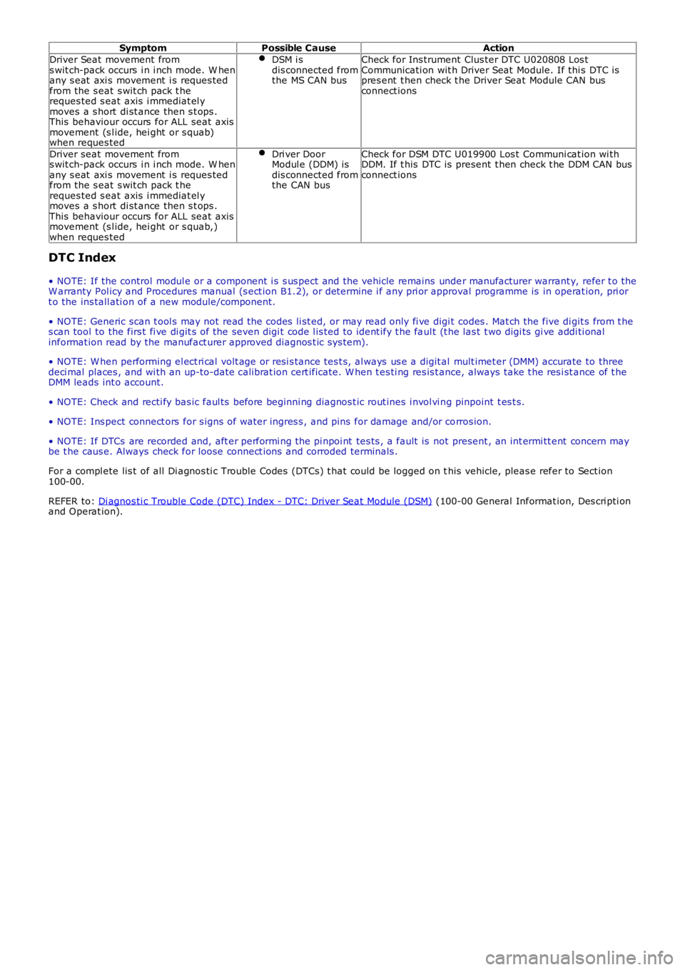
Symptom
Possible Cause Action
Driver Seat movement from
s wit ch-pack occurs i n i nch mode. W hen
any s eat axi s movement i s reques ted
from the s eat s wit ch pack t he
reques ted s eat axis i mmediat el y
moves a s hort di st ance then s t ops .
This behaviour occurs for ALL seat axis
movement (s l ide, hei ght or s quab)
when reques ted DSM i s
dis connected from
the MS CAN bus Check for Ins trument Clus ter DTC U020808 Los t
Communicati on wit h Driver Seat Module. If thi s DTC is
pres ent t hen check t he Driver Seat Module CAN bus
connect ions
Driver seat movement from
s wit ch-pack occurs i n i nch mode. W hen
any s eat axi s movement i s reques ted
from the s eat s wit ch pack t he
reques ted s eat axis i mmediat el y
moves a s hort di st ance then s t ops .
This behaviour occurs for ALL seat axis
movement (s l ide, hei ght or s quab,)
when reques ted Dri ver Door
Modul e (DDM) is
dis connected from
the CAN bus Check for DSM DTC U019900 Los t Communi cat ion wi th
DDM. If t his DTC is present t hen check t he DDM CAN bus
connect ions
DTC Index
• NOTE: If the control modul e or a component i s s us pect and the vehicle remains unde r manufacturer warrant y, refer t o the
W arranty Pol icy and Procedures manual (s ect ion B1.2), or determine i f any pri or appr oval programme is in operat ion, pri or
t o the ins tall ati on of a new module/component.
• NOTE: Generic scan t ool s may not read the codes li st ed, or may read only fi ve digi t codes . Mat ch the five di git s from t he
s can tool to the firs t fi ve di git s of the seven digi t code l is ted to ident ify t he fa ul t (t he las t t wo digi ts gi ve addi ti onal
informat ion read by the manufact urer approved diagnos t ic s ys tem).
• NOTE: W hen performing el ect ri cal volt age or resi s tance tes t s, al ways us e a digit al mult imet er (DMM) accurate to three
deci mal places , and wi th an up-to-date cali brat ion cert ificate. W hen t es ti ng res is t a nce, always take t he res i st ance of t he
DMM leads int o account.
• NOTE: Check and recti fy bas ic faul ts before beginni ng diagnos t ic rout ines i nvol vi n g pinpoint t es t s.
• NOTE: Ins pect connect ors for s igns of water ingres s , and pins for damage and/or co rros ion.
• NOTE: If DTCs are recorded and, aft er performi ng the pi npoi nt tes ts , a fault is no t present , an int ermi tt ent concern may
be t he caus e. Always check for loose connect ions and corroded terminals .
For a compl ete lis t of all Di agnos ti c Trouble Codes (DTCs) t hat could be logged on t his vehicle, pleas e refer to Sect ion
100-00.
REFER to: Di agnos ti c Trouble Code (DTC) Index - DTC: Driver Seat Module (DSM) (100-00 General Informat ion, Des cri pti on
and Operat ion).
Page 2235 of 3229
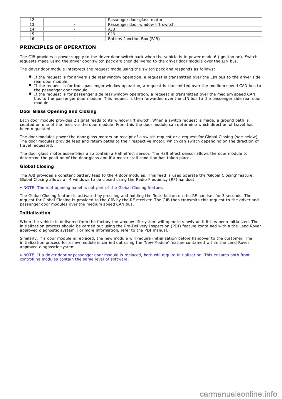
12-Pass enger door glas s mot or
13-Pass enger door wi ndow lift s wit ch
14-AJB15-CJB
16-Batt ery Junct ion Box (BJB)
PRINCIPLES OF OPERATION
The CJB provides a power s uppl y t o the driver door s wi tch pack when t he vehi cl e is in power mode 6 (i gni ti on on). Swit chreques ts made us i ng the driver door s wi tch pack are t hen deli vered to the driver door module over t he LIN bus .
The dri ver door module i nterprets t he reques t made us ing t he s wit ch pack and res ponds as follows :
If the reques t is for dri vers s ide rear window operat ion, a reques t is t rans mit t ed over t he LIN bus to the driver si derear door modul e.If the reques t is for front pas s enger wi ndow operati on, a reques t i s t ransmit ted over the medium speed CAN bus t ot he pas s enger door modul e.If the reques t is for pass enger s i de rear window operat ion, a reques t is trans mi tt ed over the medi um s peed CANbus to the pas s enger door modul e. Thi s request is t hen forwarded over t he LIN bus t o the pas s enger s ide rear doormodule.
Door G lass Opening and Closing
Each door module provides 2 s ignal feeds t o it s wi ndow li ft s wit ch. W hen a s wi tch reques t is made, a ground pat h i screated on one of the l ines via the door module. From this the door module can det ermi ne which direct ion of t ravel hasbeen request ed.
The door modul es power t he door gl ass motors on receipt of a s wi tch reques t or a reques t for Global Clos ing (s ee below).The door modul es provide feed and ret urn pat hs to their respecti ve motor, which can s wit ch depending on t he direct ion oft ravel reques t ed.
The door gl ass motor as sembl ies als o contai n a Hal l effect s ens or. The Hal l effect sens or all ows the door module todetermine t he pos it ion of t he door glas s and i f a mot or st all condi ti on has taken place.
Global Closing
The AJB provides a cons tant batt ery feed to the 4 door modules . This feed is us ed operat e t he 'Gl obal Clos ing' feat ure.Global Clos ing al lows all 4 windows t o be clos ed usi ng t he Radi o Frequency (RF) hands et.
• NOTE: The roof opening panel i s not part of the Global Cl osi ng feat ure.
The Global Clos ing feat ure is acti vat ed by pres s ing and hol di ng t he 'l ock' but ton on the RF hands et for 3 s econds . Thereques t for Global Clos ing i s provided t o t he CJB by t he RF receiver. The CJB t hen trans mi ts thi s request t o t he dri ver andpass enger door modules over the medi um s peed CAN bus .
Initialization
W hen t he vehicle i s deli vered from t he fact ory t he wi ndow lift s yst em will operat e slowl y unt il i t has been init ial ized. Theini ti al izati on process should be carri ed out usi ng the Pre-Del ivery Ins pecti on (PDI) feat ure contai ned wit hin t he Land Roverapproved diagnos t ic s yst em. For more informati on, refer t o t he PDI manual .
Simi larly, if a door module is repl aced, t he new module will requi re init iali zat ion before handover t o t he cus t omer. Theini ti al izati on process for a new modul e i s carri ed out us i ng the 'New Module' feat ure contai ned wit hi n t he Land Roverapproved diagnos t ic s yst em.
• NOTE: If a dri ver door or pas s enger door modul e i s replaced, bot h wi ll require i niti ali zat ion. Thi s ens ures both frontcont rol ling modul es cont ain t he s ame l evel of s oft ware.
Page 2311 of 3229
Hood Ajar Switch
The RH hood lat ch incorporat es the hood ajar s wi tch t hat is hardwired t o t he CJB. If t he i gniti on is in power modes 4(Acces sory) or 6 (Ignit ion) and the hood is opened or is not ful ly closed, t he hood ajar switch is opened t o dis connect theground from t he CJB. A mess age i s trans mitt ed by t he CJB via the medi um s peed CAN bus t o the i ns trument clust er, toinform the dri ver t hat the hood is ajar.
On vehicl es with a low-li ne inst rument clus ter t he hood ajar symbol is i llumi nated.For addit ional informat ion, refer t o: Inst rument Clus ter (413-01 Ins trument Clust er, Des cription and Operat ion).On vehicl es with a high-l ine i ns trument clust er, t he hood ajar s ymbol is il luminat ed and a mes sage i s als o dis pl ayed in t hemess age cent er.For addit ional informat ion, refer t o: Informat ion and Mes sage Center (413-08 Informati on and Mes sage Center, Descriptionand Operat ion).
The hood ajar s wi tch i s als o i nt egrated wit h the vehicle securit y system and is used as the detecti on device for unauthorizedvehicle ent ry.For addit ional informat ion, refer t o: Anti -Theft - Act ive (419-01A Anti-Theft - Act ive, Description and Operat ion).
LIFTGATE LATCH
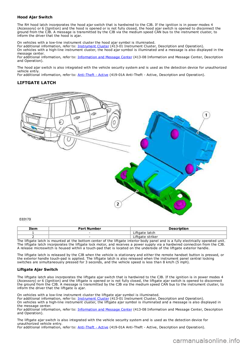
ItemPart NumberDescription
1-Li ftgat e lat ch2-Li ftgat e st rikerThe lift gate latch is mount ed at t he bott om center of the lift gate interior body panel and is a fully el ectri cally operat ed uni t.The lift gate latch incorporates t he li ftgate lock mot or, and receives a power supply vi a a hardwired connecti on from t he CJB.A rel ease microswitch is hous ed wit hin a touch-pad that is located on the unders ide of the l ift gate exteri or handle.
The lift gate latch is released by t he CJB when t he vehicle is st at ionary and eit her t he remot e handset button is pres sed, orthe ext erior handl e t ouch-pad is applied. The li ftgat e lat ch is als o rel eased when the inst rument panel cent ral lockingswitches are simultaneousl y press ed for 3 seconds, and the vehicle s peed is less t han 8 km/h (5 mph).
Liftgate Ajar Switch
The lift gate latch als o incorporates the l ift gate ajar swit ch that i s hardwired to the CJB. If t he igni tion is in power modes 4(Acces sory) or 6 (Ignit ion) and the l ift gate is opened or is not ful ly cl os ed, t he li ftgat e ajar swit ch is opened t o dis connectthe ground from the CJB. A mes sage i s t rans mi tted by t he CJB vi a t he medium s peed CAN bus t o t he inst rument cluster, toinform the dri ver t hat the l ift gate is ajar.
On vehicl es with a low-li ne inst rument clus ter t he li ftgate ajar symbol i s i lluminated.For addit ional informat ion, refer t o: Inst rument Clus ter (413-01 Ins trument Clust er, Des cription and Operat ion).On vehicl es with a high-l ine i ns trument clust er, t he liftgat e ajar symbol is il luminated and a message i s als o dis pl ayed inthe mess age cent er.For addit ional informat ion, refer t o: Informat ion and Mes sage Center (413-08 Informati on and Mes sage Center, Descriptionand Operat ion).
The lift gate ajar s wi tch i s als o int egrated wit h the vehicle securit y system and is used as the detect ion device forunauthorized vehi cle ent ry.For addit ional informat ion, refer t o: Anti -Theft - Act ive (419-01A Anti-Theft - Act ive, Description and Operat ion).
Page 2317 of 3229
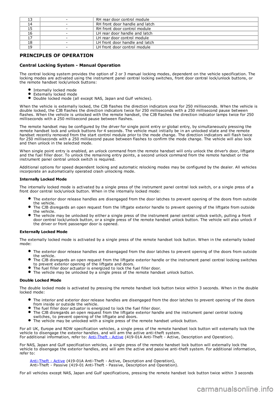
13-RH rear door cont rol module14-RH front door handl e and l at ch15-RH front door control module16-LH rear door handle and latch17-LH rear door cont rol modul e18-LH front door handle and l atch19-LH front door control module
PRINCIPLES OF OPERATION
Central Locking System - Manual Operation
The central locking s ys tem provides the option of 2 or 3 manual l ocking modes , dependent on the vehicle s pecificati on. Thelocki ng modes are acti vated usi ng t he inst rument panel cent ral locking switches, front door cent ral lock/unl ock but tons , orthe remote hands et lock/unlock butt ons:
Internall y l ocked modeExternal ly locked modeDouble l ocked mode (all except NAS, Japan and Gulf vehicles).
W hen the vehicle is externall y l ocked, the CJB flashes the di recti on indi cators once for 250 mi llis econds . W hen t he vehicle isdouble locked, t he CJB fl as hes the direct ion indicators t wi ce for 250 mil lis econds with a 250 mill isecond pause bet weenflashes . W hen t he vehicl e is unlocked with the remote hands et , t he CJB fl as hes the direction indicat or lamps twice for 250mi lli seconds wit h a 250 mi llis econd paus e between flashes.
The remote hands et may be confi gured by the dri ver for si ngle point ent ry or global ent ry, by s imultaneousl y press ing theremote hands et lock and unlock but tons for 4 s econds . The vehicle mus t i nit ially be i n an unlocked s tat e and the remotehandset recentl y removed from the start control module prior t o t he mode change. The di rection indi cat ors wil l flas h twicefor 250 mill iseconds with a 250 mill isecond pause bet ween flas hes to confirm the mode change. The vehi cle will also lockand then unlock in t he select ed mode.
W hen singl e point ent ry is enabled, an unl ock command from t he remot e handset wil l onl y unl ock the driver's door, l ift gateand the fuel fill er door. To unlock the remaining ent ry points , a s econd unlock command from the remote handset or theins trument panel central unlock swit ch is required.
Addi tional options for speed dependent locki ng and automat ic relocki ng modes may be configured by the deal er. All vehiclesincorporate an aut omatical ly operat ed cras h unlocki ng mode.
Internally Locked Mode
The int ernally locked mode is acti vated by a single pres s of the i ns trument panel central lock switch, or a s ingle pres s of afront door central lock/unlock butt on. W hen i n t he i nternal ly locked mode:
The exterior door releas e handles are di sengaged from the door lat ches t o prevent openi ng of the doors from outs idethe vehi cle.The CJB di sregards an open request from the l ift gate exterior handle to prevent opening of the lift gate from outsi dethe vehi cle.The vehi cle may be unlocked by eit her a s ingle press of the instrument panel cent ral unlock s wi tch, pulling a frontdoor central l ock/unlock butt on, or a s ingle press of t he remot e handset unl ock button. The vehicle wil l also unl ock i fthe driver or front pas senger door is opened.
Externally Locked Mode
The externally l ocked mode is act ivated by a si ngle pres s of the remote hands et lock butt on. W hen i n t he ext ernally lockedmode:
The exterior door releas e handles are di sengaged from the door lat ches t o prevent openi ng of the doors from outs idethe vehi cle.The CJB di sregards an open request from the l ift gate exterior handle or the inst rument panel cent ral locking s witchesto prevent exterior opening of the l ift gate and doors.The fuel fil ler door act uator i s energized t o l ock t he fuel filler door.The vehi cle may be unlocked by a s ingle press of the remote hands et unl ock but ton.
Double Locked Mode
The double locked mode is activat ed by pres sing the remote hands et lock butt on twice wi thin 3 seconds. W hen in the doublelocked mode:
The interior and ext erior door releas e handles are dis engaged from the door latches to prevent opening of the doorsfrom ins ide or out si de the vehi cle.The fuel fil ler door act uator i s energized t o l ock t he fuel filler door.The CJB di sregards an open request from the l ift gate exterior handle and the ins trument panel central lockingswit ches , t o prevent openi ng of t he li ftgat e and doors.The vehi cle may be unlocked with a s ingle pres s of the remote hands et unlock but ton.
For all UK, Europe and ROW s peci ficat ion vehicles , a s ingl e press of t he remot e handset l ock button wi ll externally lock t hevehicle to dis engage t he exterior handles, and wi ll arm the act ive ant i-t heft syst em.For addit ional informat ion, refer t o: Anti -Theft - Act ive (419-01A Anti-Theft - Act ive, Description and Operat ion).
For NAS, Japan and Gulf specifi cat ion vehicles, a singl e press of t he remot e handset lock button will externall y l ock t hevehicle to dis engage t he exterior handles, and wi ll arm the act ive and pas si ve anti -theft s ys tem. For additi onal informati on,refer to:
Ant i-Theft - Active (419-01A Anti -Theft - Active, Des cri pti on and Operation),Ant i-Theft - Pass ive (419-01 Ant i-Theft - Pass ive, Description and Operat ion).
For all vehi cles except NAS, Japan and Gul f s pecificati ons, pres si ng the remote hands et lock but ton t wi ce within 3 seconds