2006 LAND ROVER FRELANDER 2 ECO mode
[x] Cancel search: ECO modePage 2504 of 3229
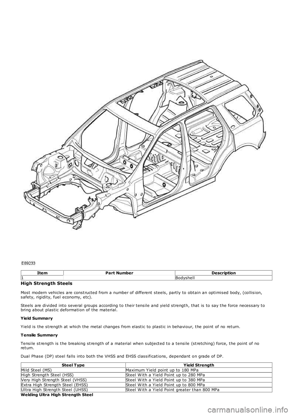
ItemPart NumberDescription1Bodyshell
High Strength Steels
Mos t modern vehicles are cons t ructed from a number of different s teels , part ly to obt ain an opt imi s ed body, (col lis i on,s afety, rigidi ty, fuel economy, etc).
Steels are di vi ded int o s everal groups according t o t heir t ens il e and yiel d s trengt h, that is to say t he force neces s ary t obri ng about pl as t ic deformati on of the material.
Yield Summary
Y iel d is the s t rength at whi ch the metal changes from el ast ic to pl ast ic in behavi our, t he poi nt of no ret urn.
T ensile Summary
Tens i le s t rength is t he breaking s t rength of a material when s ubject ed t o a t ensi le (s t retching) force, t he point of noret urn.
Dual Phas e (DP) st eel fall s int o both the VHSS and EHSS cl as s ificati ons , dependant on grade of DP.
Steel T ypeYield Strength
Mi ld St eel (MS)Maximum Y ield poi nt up to 180 MPaHi gh Strengt h Steel (HSS)Steel W i th a Y iel d Point up t o 280 MPa
Very High St rength St eel (VHSS)Steel W i th a Y iel d Point up t o 380 MPa
Extra Hi gh Strengt h Steel (EHSS)Steel W i th a Y iel d Point up t o 800 MPaUl tra High St rengt h Steel (UHSS)Steel W i th a Y iel d Point greater t han 800 MPa
Welding Ultra High Strength Steel
Page 2513 of 3229
Connect t he ground connecti on of the el ect ri cal welder direct ly t o t he part t hat is t o be wel ded. Ens ure t hat thereare no electrically ins ul ati ng part s between t he ground connecti on and t he welding poi nt .Adjacent vehicle parts and adjacent vehicles mus t be s hielded agains t flying s parks and heat.
Resistance spot welding
W here res is t ance s pot welds have been used in producti on, they mus t be reproduced with new s pot wel ds in replacementwhere pos s ible. Al l s uch reproducti on s pot wel ds s houl d be s paced 25 to 30mm apart .
Sett ing up the equipment and co-ordi nat ing the wel di ng paramet ers .
Equi pment:- Follow the equi pment manufact urer's ins t ructi ons for the equipment s ett ings .- Select the correct el ect rode arms (as s hort as poss i bl e).- Ali gn t he elect rode arms and t ips exactl y.- Electrode ti ps s houl d be convex (rough s hapi ng wi th a fi le, fi ne s hapi ng wit h a sanding bl ock).Body:- Ensure t hat t he flanges to be joi ned lie perfectl y flat t o one anot her.- Prepare a bare metal joi nt surface (ins ide and outs i de).Notes on techni que/met hod:- Carry out a t est wel d on a sampl e piece of the material coat ed in welding pas te.- If any metal part s are locat ed between t he elect rode arms then t here will be a loss of inducti on and thereforepower (adjus t current s ett ing).- The power needs t o be adjus t ed for high-st rengt h low alloy s t eel .- Repeat ed weldi ng on old wel ding point s oft en l eads t o poor qual it y welds .- Keep t he elect rode ti ps as near as pos si ble t o an angle of 90° to t he contact surface.- Keep t he pres sure on t he electrodes for a s hort peri od aft er fi ni s hi ng t he weld.- The electrodes work bes t if t hei r s hape i s convex. Clean t he cont act s urface of the el ect rodes regularly.
Resistance spot welding panels where the total thickness is 3 mm or more
For al l repairs to modern Land Rover vehicles , s pot -wel ding equipment s houl d be s uitabl e for reli abl e weldi ng ofzinc-plat ed, hi gh-s trengt h and hi gh-tens il e s teels in t hree or more l ayers, up t o 5 mm tot al t hicknes s . If t heserequirements are not ful fi lled, plug wel ding mus t be us ed for s afet y reas ons. The elect ri cal s peci fi cat ions (current,res is t ance, heat ) of t he spot -wel di ng equipment have di fferent val idi ty, depending upon t he t ype of equipment . Therefore,it i s es sent ial that t he manufacturer's ins truct ions are obs erved wi th regard to the actual weldi ng performance.
MIG/MAG welding
Sett ing up the equipment and co-ordi nat ing the wel di ng paramet ers .
Any joi ns that are MIG/MAG wel ded in product ion mus t als o be MIG/MAG wel ded during repairs . Al so during repai rs ,s ome res i st ance spot welds need t o be replaced by plug wel ds .If access is diffi cul t, or i f a s uit abl y powerful s pot welder (s ee above) for tot al panel thi ckness es of 3 mm or moreis not avail abl e, res is tance s pot wel ding mus t be parti al ly replaced by plug wel di ng duri ng repairs. In t his cas e, t heincreas ed t ime needed and t he corres pondi ngl y more demandi ng corros ion protecti on requirements , mus t be t akenint o account.W el di ng repairs can only be carried out properly i f the equipment i s s et up correctly and all t he weldi ng parametersare co-ordinat ed.Equi pment:- Set up t he equi pment as di rected by the manufact urer.- The hoses must be unt wis t ed.- The core mus t be free of abraded rod part icles .- The gas and current nozzl es mus t be free of s lag and s cale resi due.- Pay att enti on to the quali ty of t he wel di ng rod and the t hroughput of gas .Body:- Ensure t hat t he joint s urface i s perfect .- Prepare a bare metal joi nt surface.- Maint ain t he correct gaps (format ion of roots ).Notes on techni que/met hod:-• NOTE: The increas ed applicati on of heat during MIG wel ding des troys t he wel di ng pri mer/zinc layer over amuch larger area t han during resi s tance s pot wel di ng, as a res ult of whi ch much more care needs t o be takenwhen applying ant i-corros ion prot ect ion aft erwards .
• NOTE: A t es t weld s hould al ways be carri ed out to ens ure that the welded joi nt is not jus t a surfaceconnecti on.
Att ach the ground cabl e ri ght next t o t he welding poi nt (ensure t hat good contact is made).- Duri ng plug wel ding s tart welding on the lower panel t o ensure adequat e penet rat ion.
Plug wel ding
Page 2725 of 3229

Contents
5
R
ENGINE COOLANT CHECK ............................ 163
BRAKE AND CLUTCH FLUID CHECK ............. 165
POWER STEERING FLUID CHECK ................ 166
WASHER FLUID CHECK ................................ 167
TECHNICAL SPECIFICATIONS ...................... 169
Vehicle battery
BATTERY WARNING SYMBOLS ................... 171
BATTERY CARE ............................................ 171
USING BOOSTER CABLES ............................ 173
CHARGING THE VE HICLE BATTERY ............. 174
CHANGING THE VE HICLE BATTERY ............. 174
Wheels and tyres
GENERAL INFORMATION ............................. 176
TYRE CARE ................................................... 177
USING WINTER TYRES................................. 183
CHANGING A ROAD WHEEL ......................... 183
TYRE REPAIR KIT ......................................... 187
USING SNOW CHAINS.................................. 192
TYRE GLOSSARY.......................................... 193
TECHNICAL SPECIFICATIONS ...................... 194
Fuses
FUSE BOX LOCATIONS ................................. 195
CHANGING A FUSE ....................................... 195
FUSE SPECIFICATION CHART....................... 196
Emergency equipment
HAZARD WARNING FLASHERS .................... 204
WARNING TRIANGLE ................................... 204
Status after a collision
DRIVING AFTER A COLLISION...................... 205
INSPECTING SAFETY SYSTEM COMPONENTS ...
206
Vehicle recovery
TOWING POINTS .......................................... 207
LASHING POINTS ......................................... 208
TRANSPORTING THE VEHICLE..................... 208
TOWING THE VEHICLE ON FOUR WHEELS .. 208
Vehicle identification
VEHICLE IDENTIFICATION PLATE................. 210
VEHICLE IDENTIFI CATION NUMBER (VIN) ... 210
VEHICLE BUILD DATE PLATE ....................... 210
Technical specifications
ENGINE SPECIFICATIONS ............................ 211
WEIGHTS...................................................... 212
DIMENSIONS................................................ 213
Type approval
Declarations of conformity ........................... 215
Audio introduction
RADIO RECEPTION....................................... 218
Audio unit overview
AUDIO UNIT OVERVIEW............................... 219
Audio unit operation
ON OR OFF CONTROL .................................. 223
VOLUME CONTROL ...................................... 223
AUDIO CONTROL ......................................... 223
WAVEBAND BUTTON ................................... 224
AUTOSTORE CONTROL ................................ 225
STATION PRESET BUTTONS ........................ 226
TRAFFIC INFORMATION CONTROL .............. 226
Audio unit menus
RADIO DATA SYSTEM (RDS) ....................... 228
REGIONAL MODE (REG) .............................. 228
ENHANCED OTHER NETWORK (RDS-EON).. 229
ALTERNATIVE FREQUENCIES ...................... 229
NEWS BROADCASTS ................................... 230
PRIORITY PROGRAMME TYPE (PTY) .......... 231
RESETTING THE AUDIO UNIT ...................... 233
Digital audio broadcasting
GENERAL INFORMATION ............................. 234
AUDIO CONTROLS ....................................... 235
DISPLAY OPTIONS ....................................... 236
CHANNEL AUTOMATIC TUNING................... 236
CHANNEL OPTIONS ..................................... 236
PRESET BUTTONS ....................................... 238
SETTINGS..................................................... 240
Compact disc player
LOADING COMPACT DISCS ......................... 245
EJECTING COMPACT DISCS ........................ 246
EJECTING MULTIPLE CO MPACT DISCS....... 246
COMPACT DISC SELECTION ........................ 246
COMPACT DISC PLAYBACK ......................... 246
Page 2727 of 3229
7
Quick start
R
Quick startQUICK START
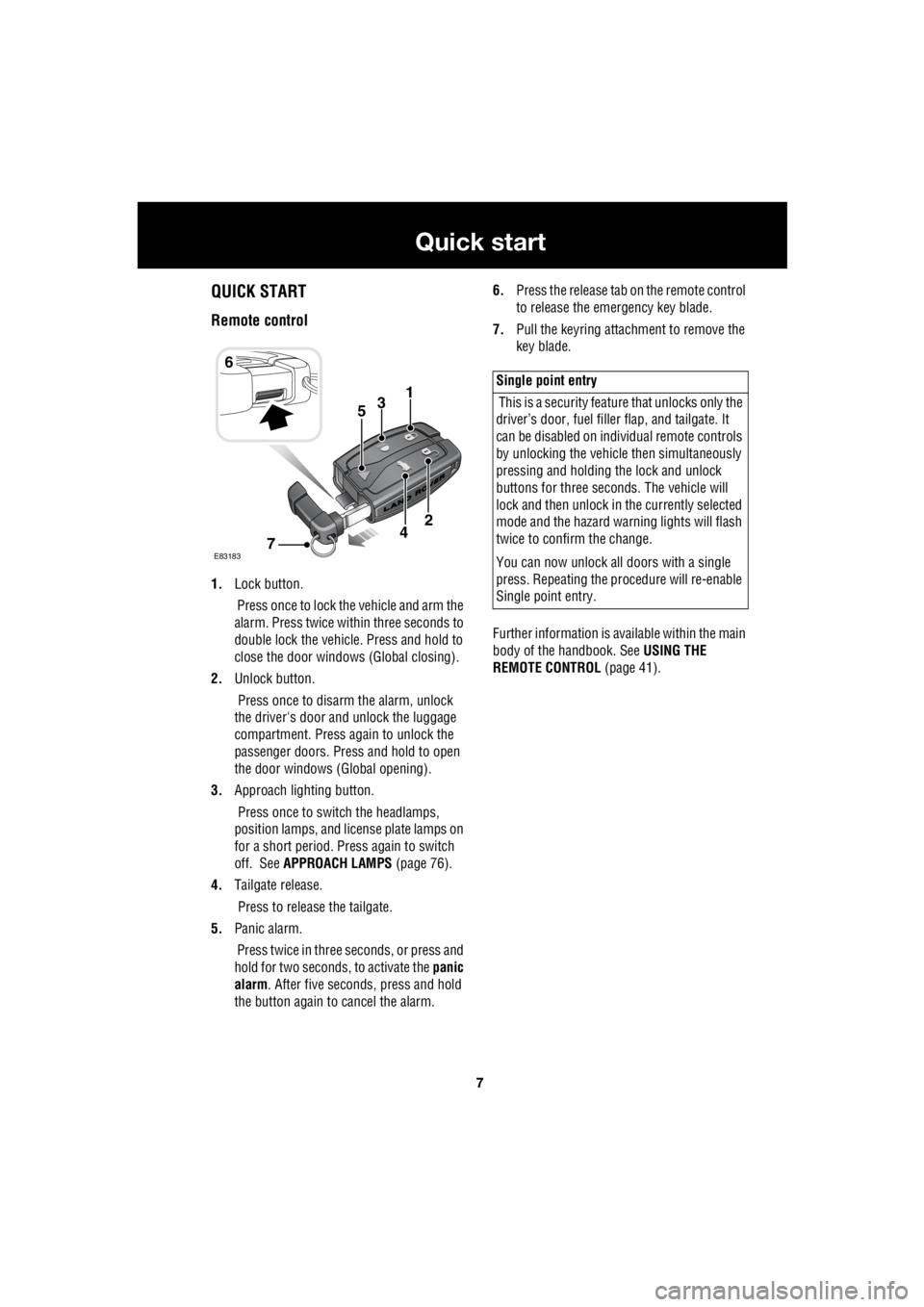
Remote control
1. Lock button.
Press once to lock the vehicle and arm the
alarm. Press twice within three seconds to
double lock the vehicle. Press and hold to
close the door windows (Global closing).
2. Unlock button.
Press once to disarm the alarm, unlock
the driver's door and unlock the luggage
compartment. Press again to unlock the
passenger doors. Press and hold to open
the door windows (Global opening).
3. Approach lighting button.
Press once to switch the headlamps,
position lamps, and license plate lamps on
for a short period. Press again to switch
off. See APPROACH LAMPS (page 76).
4. Tailgate release.
Press to release the tailgate.
5. Panic alarm.
Press twice in three seconds, or press and
hold for two seconds, to activate the panic
alarm . After five seconds, press and hold
the button again to cancel the alarm. 6.
Press the release tab on the remote control
to release the emergency key blade.
7. Pull the keyring attachment to remove the
key blade.
Further information is available within the main
body of the handbook. See USING THE
REMOTE CONTROL (page 41).
6
31
E83183
2
74
5
Single point entry
This is a security feature that unlocks only the
driver’s door, fuel fille r flap, and tailgate. It
can be disabled on indi vidual remote controls
by unlocking the vehicle then simultaneously
pressing and holding th e lock and unlock
buttons for three sec onds. The vehicle will
lock and then unlock in the currently selected
mode and the hazard wa rning lights will flash
twice to confirm the change.
You can now unlock all doors with a single
press. Repeating the pr ocedure will re-enable
Single point entry.
Page 2734 of 3229
14
Quick start
L
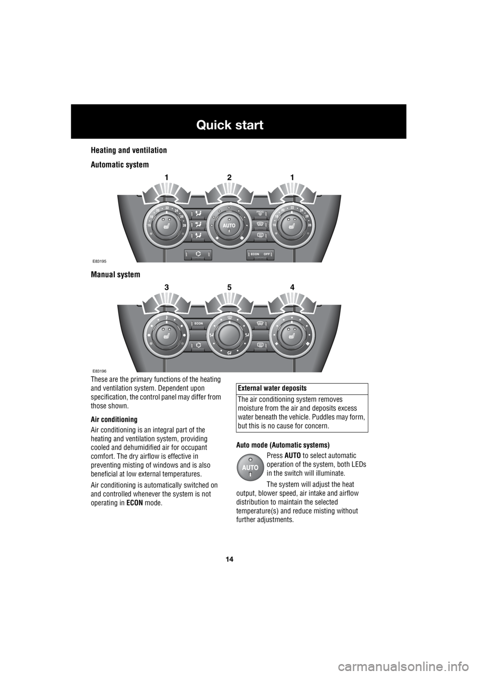
Heating and ventilation
Automatic system
Manual system
These are the primary functions of the heating
and ventilation syst em. Dependent upon
specification, the contro l panel may differ from
those shown.
Air conditioning
Air conditioning is an in tegral part of the
heating and ventilati on system, providing
cooled and dehumidifie d air for occupant
comfort. The dry airflow is effective in
preventing misting of windows and is also
beneficial at low external temperatures.
Air conditioning is automatically switched on
and controlled whenever the system is not
operating in ECON mode. Auto mode (Automatic systems)
Press AUTO to select automatic
operation of the system, both LEDs
in the switch will illuminate.
The system will adjust the heat
output, blower speed, air intake and airflow
distribution to maintain the selected
temperature(s) and re duce misting without
further adjustments.
2121
E83195
2354
E83196
External water deposits
The air conditioning system removes
moisture from the ai r and deposits excess
water beneath the vehicl e. Puddles may form,
but this is no cause for concern.
Page 2735 of 3229
15
Quick start
R
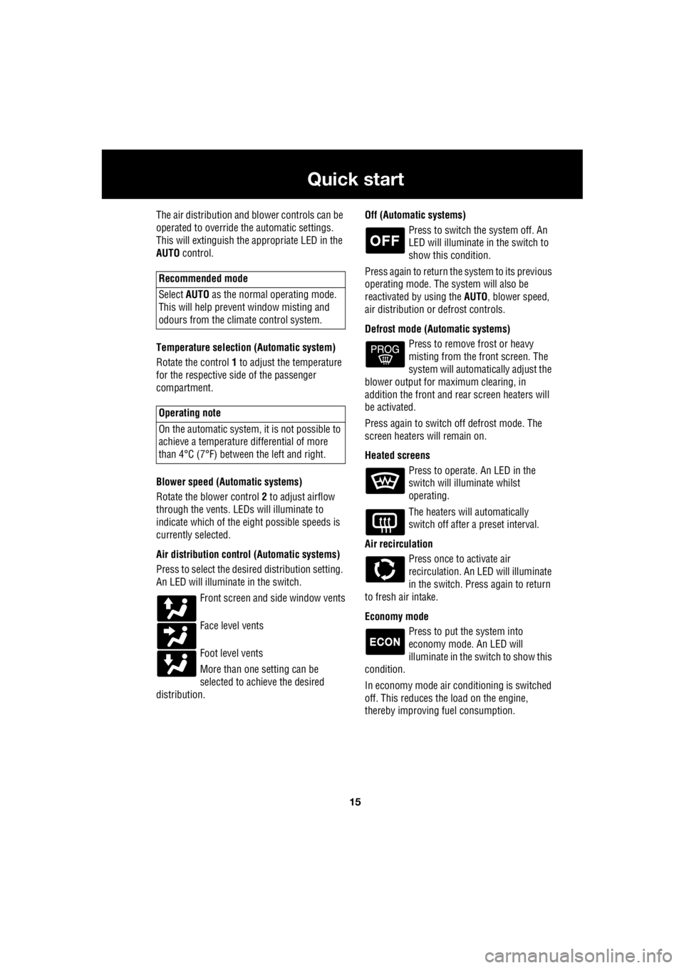
The air distribution and blower controls can be
operated to override the automatic settings.
This will extinguish the appropriate LED in the
AUTO control.
Temperature selection (Automatic system)
Rotate the control 1 to adjust the temperature
for the respective side of the passenger
compartment.
Blower speed (Automatic systems)
Rotate the blower control 2 to adjust airflow
through the vents. LEDs will illuminate to
indicate which of the ei ght possible speeds is
currently selected.
Air distribution contro l (Automatic systems)
Press to select the desi red distribution setting.
An LED will illumina te in the switch.
Front screen and side window vents
Face level vents
Foot level vents
More than one setting can be
selected to achieve the desired
distribution. Off (Automat
ic systems)
Press to switch the system off. An
LED will illuminate in the switch to
show this condition.
Press again to return the system to its previous
operating mode. The system will also be
reactivated by using the AUTO, blower speed,
air distribution or defrost controls.
Defrost mode (Automatic systems) Press to remove frost or heavy
misting from the front screen. The
system will automatically adjust the
blower output for maximum clearing, in
addition the front and rear screen heaters will
be activated.
Press again to switch off defrost mode. The
screen heaters will remain on.
Heated screens Press to operate. An LED in the
switch will illuminate whilst
operating.
The heaters will automatically
switch off after a preset interval.
Air recirculation Press once to activate air
recirculation. An LED will illuminate
in the switch. Press again to return
to fresh air intake.
Economy mode Press to put the system into
economy mode. An LED will
illuminate in the switch to show this
condition.
In economy mode air conditioning is switched
off. This reduces the load on the engine,
thereby improving fuel consumption.
Recommended mode
Select AUTO as the normal operating mode.
This will help prevent window misting and
odours from the climate control system.
Operating note
On the automatic system, it is not possible to
achieve a temperature differential of more
than 4°C (7°F) betwee n the left and right.
Page 2739 of 3229
19
Quick start
R
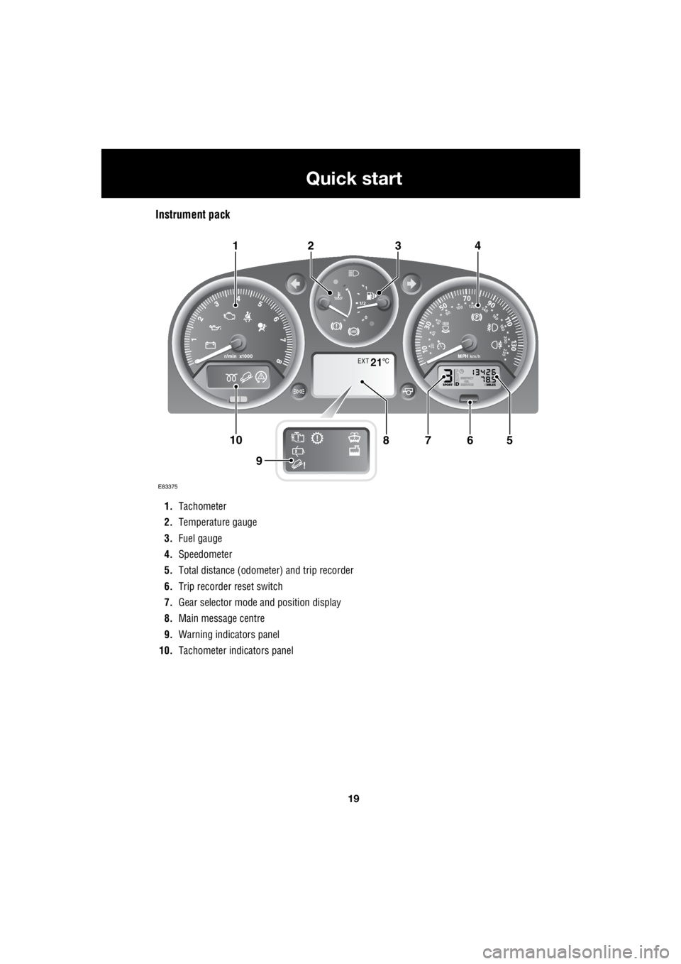
Instrument pack
1. Tachometer
2. Temperature gauge
3. Fuel gauge
4. Speedometer
5. Total distance (odometer) and trip recorder
6. Trip recorder reset switch
7. Gear selector mode and position display
8. Main message centre
9. Warning indicators panel
10. Tachometer indi cators panel
EXT C21
E83375
567108
9
1423
Page 2740 of 3229
20
Quick start
L
Tachometer
Indicates engine spee d in revolutions per
minute (x 1 000). In normal driving conditions
the engine is most fuel efficient between 2 000
and 3 000 rev/min.
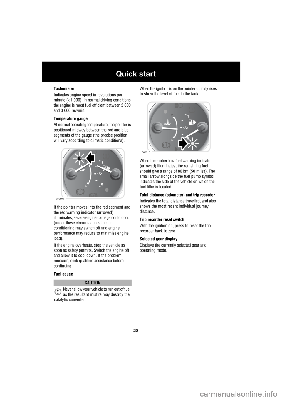
Temperature gauge
At normal operating temperature, the pointer is
positioned midway between the red and blue
segments of the gauge (the precise position
will vary according to climatic conditions).
If the pointer moves into the red segment and
the red warning indicator (arrowed)
illuminates, severe engi ne damage could occur
(under these circumstances the air
conditioning may switch off and engine
performance may reduce to minimise engine
load).
If the engine overheats, stop the vehicle as
soon as safety pe rmits. Switch the engine off
and allow it to cool down. If the problem
reoccurs, seek qualified assistance before
continuing.
Fuel gauge When the ignition is on the pointer quickly rises
to show the level of fuel in the tank.
When the amber low fuel warning indicator
(arrowed) illuminates, the remaining fuel
should give a range of 80 km (50 miles). The
small arrow alongside th e fuel pump symbol
indicates the side of the vehicle on which the
fuel filler is located.
Total distance (odometer) and trip recorder
Indicates the total distance travelled, and also
shows the most recent individual journey
distance.
Trip recorder reset switch
With the ignition on, press to reset the trip
recorder back to zero.
Selected gear display
Displays the currently selected gear and
operating mode.
CAUTION
Never allow your vehicl e to run out of fuel
as the resultant misfire may destroy the
catalytic converter.
E80509
E80510