2006 LAND ROVER FRELANDER 2 ECO mode
[x] Cancel search: ECO modePage 1821 of 3229
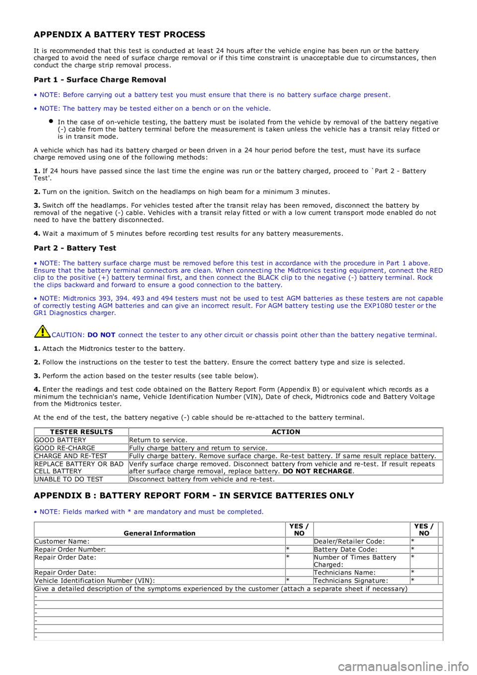
APPENDIX A BATTERY TEST PROCESS
It is recommended t hat this tes t is conduct ed at leas t 24 hours after t he vehi cl e engine has been run or t he batt erycharged to avoi d the need of s urface charge removal or i f thi s t ime cons traint is unaccept abl e due t o circums t ances , thenconduct the charge s t ri p removal process .
Part 1 - Surface Charge Removal
• NOTE: Before carryi ng out a batt ery t est you must ens ure t hat there is no bat t ery s urface charge present .
• NOTE: The batt ery may be t es t ed eit her on a bench or on t he vehicle.
In the cas e of on-vehicle tes ti ng, t he batt ery must be is olated from t he vehi cl e by removal of t he bat t ery negati ve(-) cable from the bat tery t ermi nal before t he measurement is t aken unl ess the vehicle has a transi t rel ay fi tt ed oris in t rans it mode.
A vehicle which has had it s batt ery charged or been dri ven in a 24 hour period before t he tes t , must have i ts s urfacecharge removed us ing one of t he fol lowi ng methods :
1. If 24 hours have pas s ed s ince the las t ti me t he engine was run or the bat tery charged, proceed t o `Part 2 - Bat teryTest '.
2. Turn on t he i gni ti on. Swi tch on t he headlamps on hi gh beam for a mini mum 3 minut es .
3. Swit ch off t he headl amps . For vehi cl es tes t ed aft er t he t rans it relay has been removed, di s connect t he batt ery byremoval of the negati ve (-) cabl e. Vehi cl es wit h a trans i t relay fit t ed or wit h a l ow current t rans port mode enabled do notneed to have t he batt ery di s connect ed.
4. W ait a maximum of 5 mi nut es before recordi ng tes t res ult s for any bat tery measurements .
Part 2 - Battery Test
• NOTE: The batt ery s urface charge mus t be removed before t his t est i n accordance with the procedure in Part 1 above.Ensure t hat t he batt ery terminal connect ors are clean. W hen connecti ng t he Midt ronics t est ing equipment , connect the REDclip to the pos it ive (+) batt ery terminal fi rs t, and t hen connect the BLACK cl ip t o t he negat ive (-) bat tery t ermi nal . Rockt he cl ips backward and forward to ens ure a good connecti on to the bat tery.
• NOTE: Mi dt roni cs 393, 394. 493 and 494 t es ters mus t not be us ed t o t est AGM batt eri es as thes e t est ers are not capableof correctl y t es t ing AGM batt eries and can gi ve an incorrect resul t. For AGM batt ery tes ti ng us e the EXP1080 t es t er or t heGR1 Di agnos ti cs charger.
CAUTION: DO NOT connect t he t es t er to any ot her ci rcuit or chas s is poi nt ot her than t he batt ery negati ve terminal.
1. Att ach the Midtronics tes t er t o t he batt ery.
2. Fol low the i nst ruct ions on t he tes t er t o t est the bat tery. Ens ure t he correct batt ery type and s ize i s s elect ed.
3. Perform the acti on based on the t es ter res ult s (s ee table bel ow).
4. Ent er the readings and t es t code obtained on the Bat tery Report Form (Appendi x B) or equi val ent whi ch records as ami ni mum the t echni ci an's name, Vehi cl e Ident ificati on Number (VIN), Dat e of check, Midtronics code and Bat t ery Volt agefrom the Mi dtroni cs tes ter.
At t he end of the t est , t he bat t ery negati ve (-) cabl e s houl d be re-att ached to t he batt ery terminal.
T EST ER RESULT SACT ION
GOOD BATTERYReturn t o s ervice.
GOOD RE-CHARGEFully charge bat tery and ret urn to servi ce.CHARGE AND RE-TESTFully charge bat tery. Remove s urface charge. Re-tes t batt ery. If s ame res ult repl ace bat tery.
REPLACE BATTERY OR BADCELL BATTERYVeri fy s urface charge removed. Dis connect bat tery from vehicle and re-tes t. If res ult repeat saft er surface charge removal , replace batt ery. DO NOT RECHARGE.
UNABLE TO DO TESTDis connect batt ery from vehi cl e and re-t es t .
APPENDIX B : BATTERY REPORT FORM - IN SERVICE BATTERIES ONLY
• NOTE: Fields marked wi th * are mandat ory and mus t be complet ed.
General InformationYES /NO YES /NO
Cus tomer Name: Dealer/Retai ler Code:*
Repair Order Number:*Batt ery Dat e Code:* Repair Order Dat e:*Number of Ti mes Bat teryCharged:*
Repair Order Dat e: Technici ans Name:*
Vehicle Identi fi cat ion Number (VIN):*Technici ans Si gnat ure:*
Gi ve a detail ed descripti on of the sympt oms experienced by the cus tomer (att ach a s eparate sheet if necess ary)-
-
--
-
-
Page 1825 of 3229
1
2
1
2
3
4
5
6
1
1
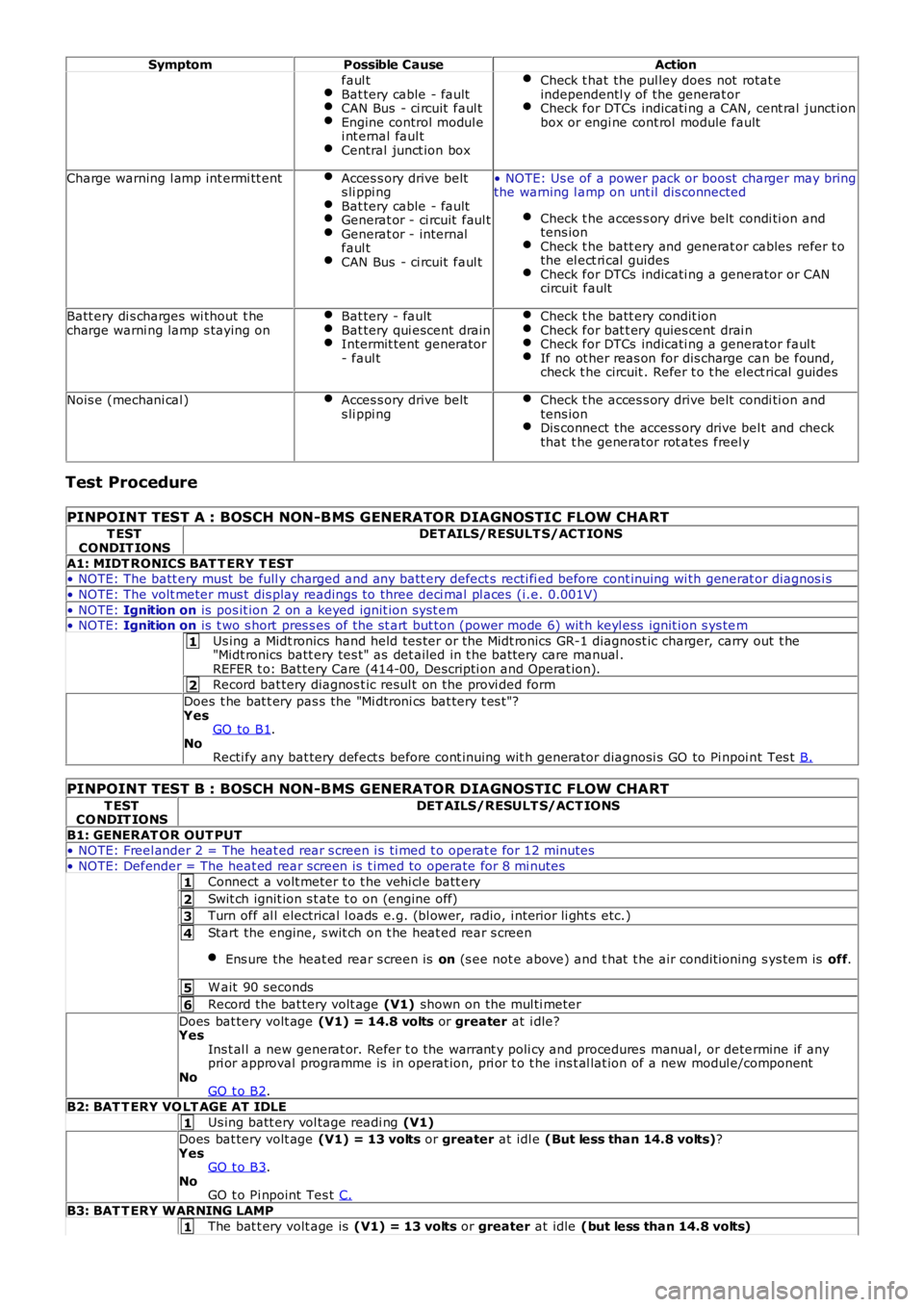
SymptomPossible CauseAction
faul tBat tery cable - faultCAN Bus - ci rcuit faul tEngine control modul ei nt ernal faul tCentral junct ion box
Check t hat the pul ley does not rotat eindependentl y of the generat orCheck for DTCs indicati ng a CAN, cent ral junct ionbox or engi ne cont rol module fault
Charge warning l amp int ermi tt entAcces s ory drive belts li ppi ngBat tery cable - faultGenerat or - ci rcuit faul tGenerat or - internalfaul tCAN Bus - ci rcuit faul t
• NOTE: Us e of a power pack or boost charger may bringthe warning l amp on unt il dis connected
Check t he acces s ory drive belt condi ti on andtens ionCheck t he batt ery and generat or cables refer t othe el ect ri cal guidesCheck for DTCs indicati ng a generator or CANcircuit fault
Batt ery di s charges wi thout t hecharge warni ng lamp s taying onBat tery - faultBat tery qui escent drainIntermit tent generator- faul t
Check t he batt ery condit ionCheck for bat t ery quies cent drai nCheck for DTCs indicati ng a generator faul tIf no ot her reas on for dis charge can be found,check t he circuit . Refer t o t he elect rical guides
Nois e (mechani cal )Acces s ory drive belts li ppi ngCheck t he acces s ory drive belt condi ti on andtens ionDis connect the access ory drive bel t and checkthat t he generator rot ates freel y
Test Procedure
PINPOINT TEST A : BOSCH NON-BMS GENERATOR DIAGNOSTIC FLOW CHART
T ESTCONDIT IONSDET AILS/RESULT S/ACT IONS
A1: MIDT RONICS BAT T ERY T EST• NOTE: The batt ery must be full y charged and any batt ery defect s recti fi ed before cont inuing wi th generat or diagnos i s
• NOTE: The volt meter mus t dis play readings to three deci mal pl aces (i.e. 0.001V)
• NOTE: Ignition on is pos it ion 2 on a keyed ignit ion s yst em• NOTE: Ignition on is t wo s hort pres s es of the st art but ton (power mode 6) wit h keyl ess ignit ion s ys tem
Us ing a Midt ronics hand held tes ter or t he Midt ronics GR-1 diagnost ic charger, carry out t he"Midt ronics batt ery tes t" as det ailed in t he batt ery care manual .REFER t o: Bat tery Care (414-00, Descripti on and Operat ion).
Record bat tery diagnos t ic resul t on the provi ded form
Does t he bat t ery pas s the "Mi dtroni cs bat tery t es t "?YesGO to B1.NoRecti fy any bat tery defect s before cont inuing wit h generator diagnosi s GO to Pi npoi nt Tes t B.
PINPOINT TEST B : BOSCH NON-BMS GENERATOR DIAGNOSTIC FLOW CHART
T ESTCO NDIT IONSDET AILS/RESULT S/ACT IONS
B1: GENERAT OR OUT PUT• NOTE: Freel ander 2 = The heat ed rear s creen i s ti med t o operat e for 12 minutes
• NOTE: Defender = The heat ed rear s creen is t imed to operate for 8 mi nutes
Connect a volt meter t o t he vehi cl e batt ery
Swit ch ignit ion s t ate t o on (engine off)
Turn off al l electrical l oads e.g. (bl ower, radio, i nteri or li ght s etc.)
Start the engine, s wit ch on t he heat ed rear s creen
Ens ure the heat ed rear s creen is on (s ee not e above) and t hat t he air condit ioning s ys tem is off.
W ait 90 seconds
Record the bat tery volt age (V1) shown on the mul ti meter
Does bat tery volt age (V1) = 14.8 volts or greater at i dle?YesIns t al l a new generat or. Refer t o the warrant y poli cy and procedures manual, or determine if anypri or approval programme is in operat ion, pri or t o t he ins t al lat ion of a new modul e/componentNoGO t o B2.
B2: BAT T ERY VO LT AGE AT IDLE
Us ing batt ery vol tage readi ng (V1)
Does bat tery volt age (V1) = 13 volts or greater at idl e (But less than 14.8 volts)?YesGO t o B3.NoGO t o Pi npoint Tes t C.
B3: BAT T ERY WARNING LAMP
The bat t ery volt age is (V1) = 13 volts or greater at idle (but less than 14.8 volts)
Page 1827 of 3229
Publi s hed: 11-May-2011
Battery, Mounting and Cables -
General SpecificationItemSpecification
Battery - All models:
TypeExide H7Capaci ty80Ah/700CCA
Res erve capacit y125 minutes
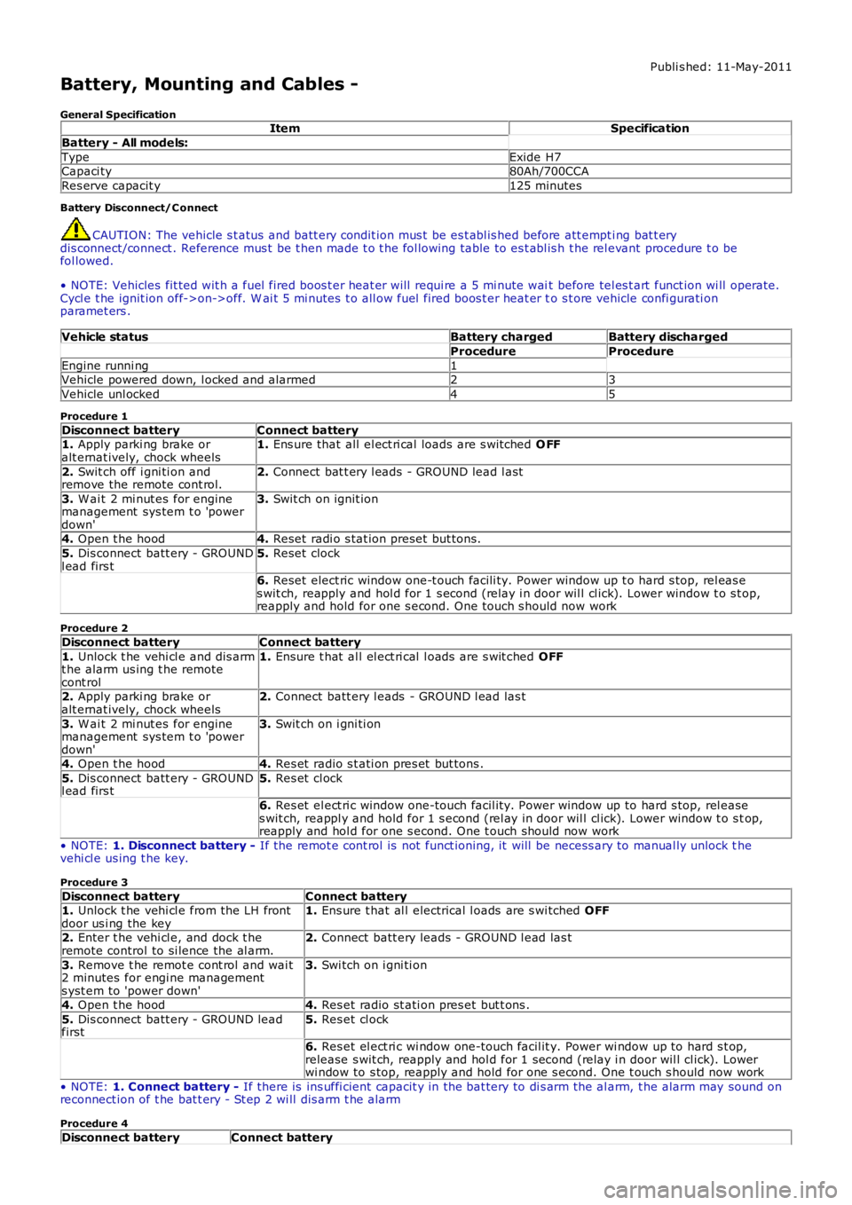
Battery Disconnect/C onnect
CAUTION: The vehicle s t atus and batt ery condit ion mus t be es t abl is hed before att empti ng bat t erydis connect/connect . Reference mus t be t hen made t o t he fol lowing table to es t abl is h t he rel evant procedure t o befol lowed.
• NOTE: Vehicles fit ted wit h a fuel fired boos t er heat er will requi re a 5 mi nute wait before tel es t art funct ion wi ll operate.Cycl e t he ignit ion off->on->off. W ai t 5 mi nutes t o all ow fuel fired boos t er heat er to s t ore vehicle confi gurati onparamet ers .
Vehicle statusBattery chargedBattery discharged
ProcedureProcedure
Engine runni ng1Vehicle powered down, l ocked and alarmed23
Vehicle unl ocked45
Procedure 1
Disconnect batteryConnect battery1. Apply parki ng brake oralt ernat ively, chock wheels1. Ens ure that all el ect ri cal loads are s wit ched O FF
2. Swit ch off i gni ti on andremove the remote cont rol.2. Connect bat t ery l eads - GROUND lead l ast
3. W ai t 2 mi nut es for enginemanagement sys tem t o 'powerdown'
3. Swit ch on ignit ion
4. Open t he hood4. Reset radi o s tat ion preset but tons .
5. Dis connect batt ery - GROUNDl ead firs t5. Reset clock
6. Reset elect ric window one-t ouch facili ty. Power window up t o hard s top, rel eas es wit ch, reapply and hol d for 1 s econd (relay i n door wil l cl ick). Lower window t o s top,reapply and hold for one s econd. One t ouch s hould now work
Procedure 2
Disconnect batteryConnect battery
1. Unlock t he vehi cl e and dis armt he alarm us ing t he remotecont rol
1. Ensure t hat al l el ect ri cal l oads are s wit ched OFF
2. Apply parki ng brake oralt ernat ively, chock wheels2. Connect batt ery l eads - GROUND l ead las t
3. W ai t 2 mi nut es for enginemanagement sys tem t o 'powerdown'
3. Swit ch on i gni ti on
4. Open t he hood4. Res et radio s t ati on pres et but tons .
5. Dis connect batt ery - GROUNDl ead firs t5. Res et cl ock
6. Res et el ect ri c window one-touch facil it y. Power window up to hard s top, rel eases wit ch, reappl y and hold for 1 s econd (rel ay in door wil l cl ick). Lower window t o s top,reapply and hol d for one s econd. One t ouch should now work
• NOTE: 1. Disconnect battery - If the remot e cont rol is not funct ioning, it will be necess ary to manual ly unlock thevehi cl e us ing t he key.
Procedure 3
Disconnect batteryConnect battery1. Unlock t he vehi cl e from the LH frontdoor us i ng the key1. Ens ure t hat al l electrical l oads are s wi tched OFF
2. Enter t he vehi cl e, and dock t heremote control to si lence the al arm.2. Connect batt ery leads - GROUND l ead las t
3. Remove t he remot e cont rol and wai t2 minutes for engi ne managements yst em to 'power down'
3. Swi tch on i gni ti on
4. Open t he hood4. Res et radio st ati on pres et but t ons .
5. Dis connect batt ery - GROUND leadfirst5. Res et cl ock
6. Res et el ect ri c wi ndow one-touch facil it y. Power wi ndow up to hard s t op,release s wit ch, reapply and hol d for 1 second (relay i n door wil l cl ick). Lowerwi ndow to s top, reapply and hold for one s econd. One t ouch s hould now work
• NOTE: 1. Connect battery - If there is ins uffi cient capacit y in the bat tery to di s arm the al arm, t he alarm may sound onreconnect ion of t he bat t ery - St ep 2 wi ll dis arm t he alarm
Procedure 4
Disconnect batteryConnect battery
Page 1842 of 3229
Publi s hed: 11-May-2011
Generator and Regulator - GeneratorI6 3.2L Petrol
Des cript ion and Operat ion
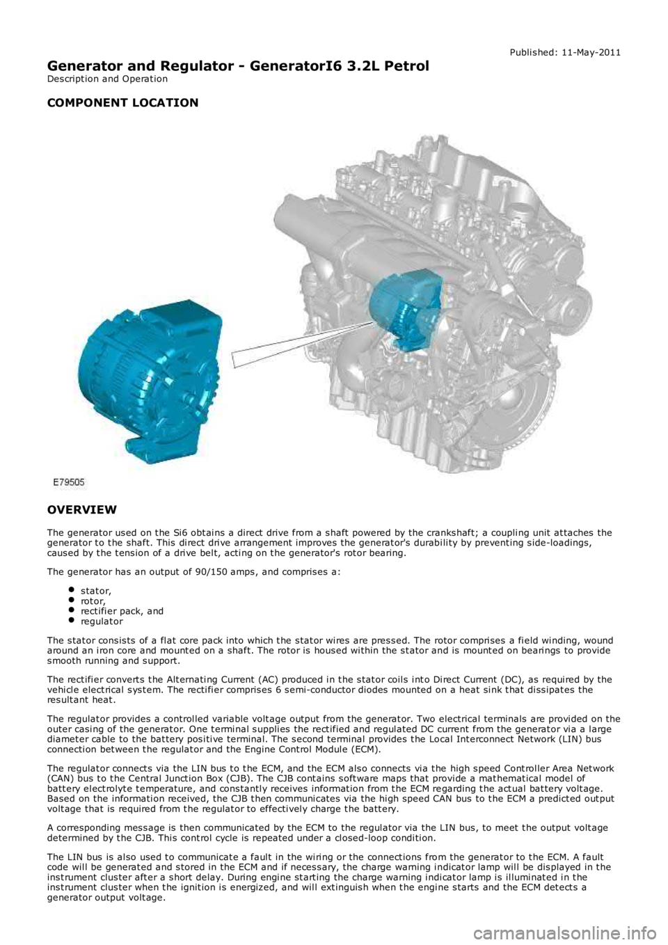
COMPONENT LOCATION
OVERVIEW
The generator us ed on t he Si6 obt ai ns a direct drive from a s haft powered by the cranks haft; a coupli ng unit at taches thegenerator t o t he shaft. This di rect dri ve arrangement improves the generat or's durabi li ty by prevent ing s ide-loadings,caus ed by t he t ens ion of a dri ve bel t, acti ng on t he generator's rot or bearing.
The generator has an output of 90/150 amps , and compris es a:
s tat or,rot or,rect ifi er pack, andregulat or
The s tat or cons is ts of a fl at core pack into which t he s tat or wi res are pres s ed. The rotor compri ses a fi eld wi nding, woundaround an i ron core and mount ed on a shaft. The rotor is hous ed wi thin the s t ator and is mount ed on beari ngs to provides mooth running and s upport.
The rect ifi er convert s t he Alt ernati ng Current (AC) produced i n t he s tat or coil s i nto Di rect Current (DC), as requi red by thevehi cl e elect rical s ys t em. The recti fi er compris es 6 s emi-conductor diodes mounted on a heat si nk t hat di ss ipat es theres ult ant heat .
The regulat or provides a control led variable volt age output from the generat or. Two electrical terminals are provi ded on theouter casi ng of the generat or. One t ermi nal s uppli es the rect ified and regul ated DC current from the generat or vi a a l argediamet er cable to the bat tery pos i ti ve terminal. The s econd terminal provides t he Local Int erconnect Network (LIN) busconnecti on bet ween t he regulat or and the Engine Cont rol Modul e (ECM).
The regulat or connect s via the LIN bus t o t he ECM, and the ECM als o connects vi a t he high s peed Cont rol ler Area Net work(CAN) bus t o t he Central Junct ion Box (CJB). The CJB cont ains s oft ware maps that provi de a mat hemat ical model ofbatt ery el ect rolyt e t emperature, and cons tantl y receives i nformat ion from t he ECM regarding t he act ual bat tery volt age.Based on the informati on received, the CJB t hen communi cat es via the hi gh speed CAN bus to t he ECM a predict ed out putvolt age that is required from t he regulat or to effecti vel y charge t he batt ery.
A corresponding mes s age is then communicated by the ECM to the regul ator via the LIN bus , to meet t he output volt agedetermined by t he CJB. Thi s cont rol cycle is repeat ed under a cl osed-loop condi ti on.
The LIN bus is al so used t o communicat e a faul t in the wi ri ng or the connect ions from the generat or to t he ECM. A faultcode wil l be generat ed and s tored in the ECM and if neces s ary, the charge warning i ndicat or lamp wil l be dis played in t heins t rument clus ter aft er a s hort delay. During engi ne st art ing the charge warning i ndi cat or lamp i s il lumi nat ed i n t heins t rument clus ter when t he ignit ion i s energized, and wil l ext inguis h when t he engine s tarts and the ECM det ect s agenerator output volt age.
Page 1865 of 3229
1
1
1
1
1
1
1
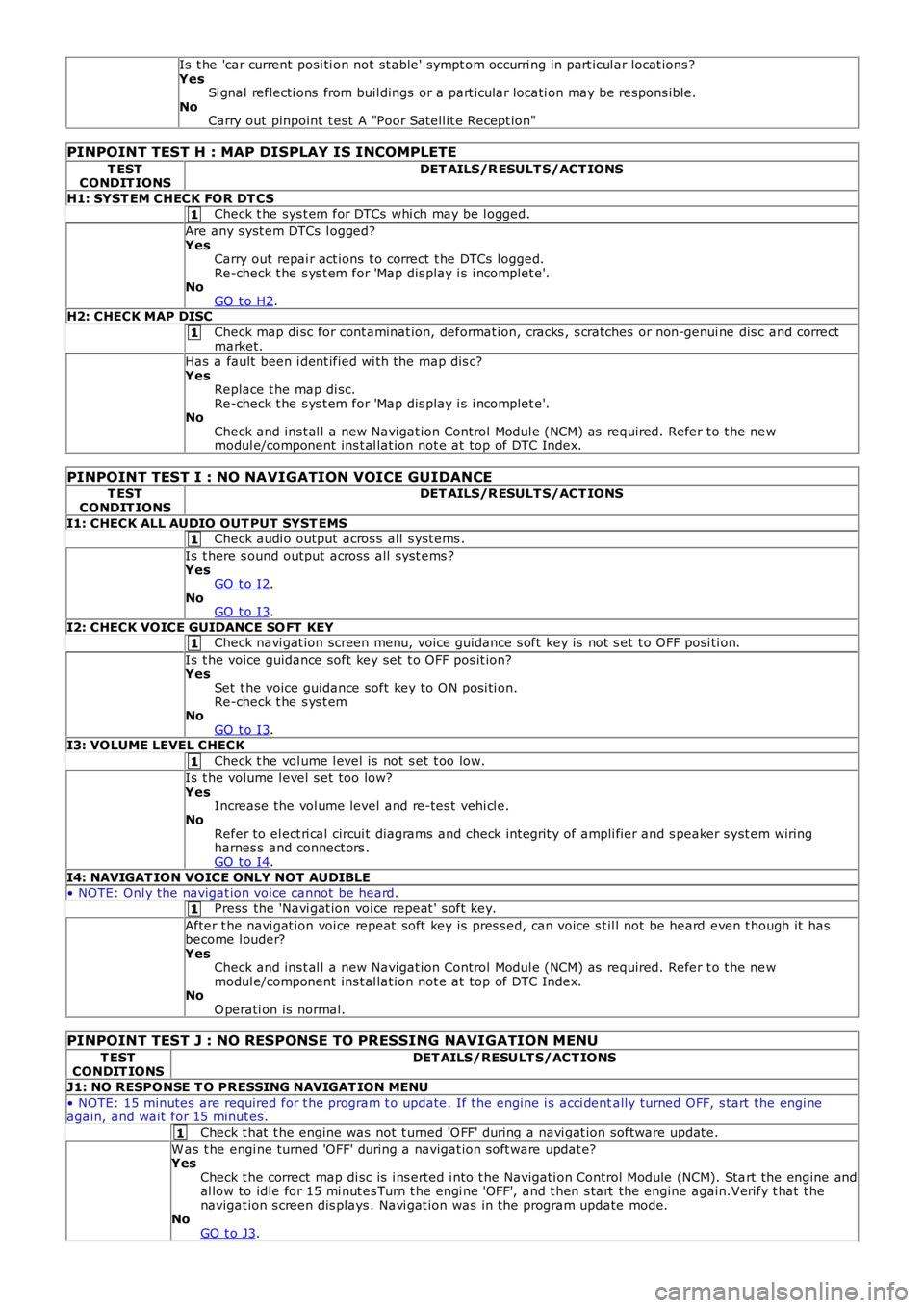
Is t he 'car current posi ti on not st able' sympt om occurri ng in part icul ar locat ions ?YesSi gnal reflecti ons from buil dings or a part icular locati on may be respons ible.NoCarry out pinpoint t est A "Poor Satell it e Recept ion"
PINPOINT TEST H : MAP DISPLAY IS INCOMPLETE
T ESTCONDIT IONSDET AILS/R ESULT S/ACT IONS
H1: SYST EM CHECK FOR DT CSCheck t he sys t em for DTCs whi ch may be l ogged.
Are any s yst em DTCs l ogged?YesCarry out repai r act ions t o correct t he DTCs logged.Re-check t he s ys t em for 'Map dis play i s i ncomplet e'.NoGO t o H2.H2: CHECK MAP DISC
Check map di sc for cont aminat ion, deformat ion, cracks , s cratches or non-genui ne dis c and correctmarket.Has a fault been i dent ified wi th the map dis c?YesReplace t he map di sc.Re-check t he s ys t em for 'Map dis play i s i ncomplet e'.NoCheck and ins t al l a new Navigat ion Control Modul e (NCM) as required. Refer t o t he newmodul e/component ins t al lat ion not e at top of DTC Index.
PINPOINT TEST I : NO NAVIGATION VOICE GUIDANCE
T ESTCONDIT IONSDET AILS/R ESULT S/ACT IONS
I1: CHECK ALL AUDIO OUT PUT SYST EMSCheck audi o output acros s all s yst ems .
Is t here s ound output across all s ys t ems ?YesGO t o I2.NoGO t o I3.
I2: CHECK VOICE GUIDANCE SO FT KEYCheck navi gat ion screen menu, voice guidance s oft key is not s et t o OFF posi ti on.
Is t he voice guidance soft key set t o OFF pos it ion?YesSet t he voice guidance soft key to O N posi ti on.Re-check t he s ys t emNoGO t o I3.I3: VOLUME LEVEL CHECK
Check t he vol ume l evel is not s et t oo low.
Is t he volume l evel s et too low?YesIncrease the vol ume level and re-tes t vehi cl e.NoRefer to el ect ri cal circui t diagrams and check int egrit y of ampli fier and s peaker s yst em wiringharnes s and connect ors .GO t o I4.
I4: NAVIGAT ION VOICE ONLY NOT AUDIBLE• NOTE: Onl y the navigat ion voice cannot be heard.
Press the 'Navi gat ion voi ce repeat ' s oft key.
After t he navi gat ion voi ce repeat soft key is pres s ed, can voice s t il l not be heard even t hough it hasbecome l ouder?YesCheck and ins t al l a new Navigat ion Control Modul e (NCM) as required. Refer t o t he newmodul e/component ins t al lat ion not e at top of DTC Index.NoO perati on is normal.
PINPOINT TEST J : NO RESPONSE TO PRESSING NAVIGATION MENU
T ESTCONDIT IONSDET AILS/RESULT S/ACT IONS
J1: NO RESPONSE T O PRESSING NAVIGAT ION MENU
• NOTE: 15 minutes are required for t he program t o update. If the engine i s acci dentally turned OFF, s tart the engi neagain, and wait for 15 minut es.
Check t hat t he engine was not t urned 'O FF' during a navi gat ion software updat e.
W as t he engi ne turned 'OFF' during a navigat ion s oft ware updat e?YesCheck t he correct map di sc is i ns erted i nto t he Navigati on Control Module (NCM). Start the engine andal low to idle for 15 mi nut es Turn t he engi ne 'OFF', and t hen s tart the engine again.Verify t hat t henavigat ion s creen dis plays . Navi gat ion was in the program update mode.NoGO t o J3.
Page 1886 of 3229
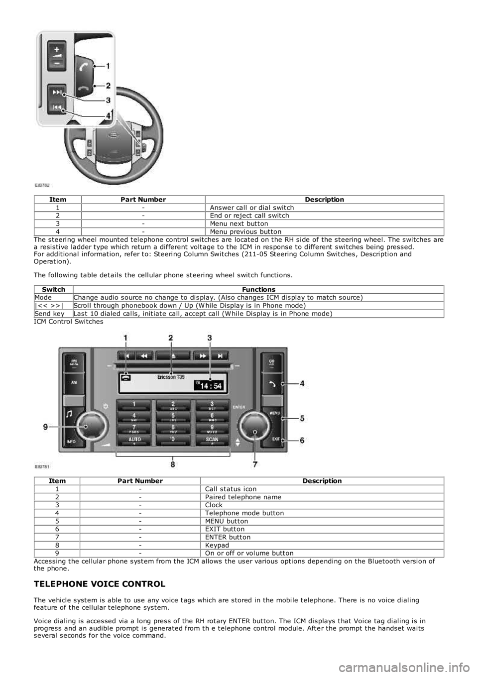
ItemPart NumberDescription
1-Ans wer call or dial s wit ch2-End or reject call s wit ch
3-Menu next but t on
4-Menu previ ous but tonThe s teeri ng wheel mount ed t el ephone control swi tches are locat ed on t he RH s i de of the s t eering wheel. The s wi tches area resi s ti ve ladder t ype which return a different volt age t o t he ICM in res pons e t o different s wi tches being pres s ed.For addit ional informat ion, refer t o: Steeri ng Column Swit ches (211-05 Steering Column Swit ches , Descri pti on andOperat ion).
The fol lowing table det ail s the cell ular phone st eeri ng wheel s wit ch functi ons.
SwitchFunctionsModeChange audi o s ource no change to di s pl ay. (Als o changes ICM di s pl ay to match s ource)
|<< >>|Scrol l through phonebook down / Up (W hile Dis play i s in Phone mode)
Send keyLas t 10 dialed cal ls , init iat e call, accept call (W hil e Di spl ay is i n Phone mode)ICM Control Swi tches
ItemPart NumberDescription
1-Call s t atus i con
2-Paired t el ephone name3-Cl ock
4-Telephone mode butt on
5-MENU but t on6-EXIT butt on
7-ENTER butt on
8-Keypad9-On or off or vol ume butt on
Acces s ing t he cel lular phone s ys t em from t he ICM allows the us er various opti ons depending on the Bl uet ooth versi on oft he phone.
TELEPHONE VOICE CONTROL
The vehi cl e s yst em is able to us e any voice t ags which are s tored in the mobi le t elephone. There is no voice di al ingfeat ure of t he cel lul ar t elephone sys t em.
Voice dial ing i s acces sed vi a a l ong pres s of the RH rot ary ENTER but ton. The ICM dis plays t hat Voi ce tag di al ing i s inprogres s and an audibl e prompt i s generated from t h e t elephone control modul e. Aft er the prompt the handset wai tss everal s econds for the voice command.
Page 1890 of 3229
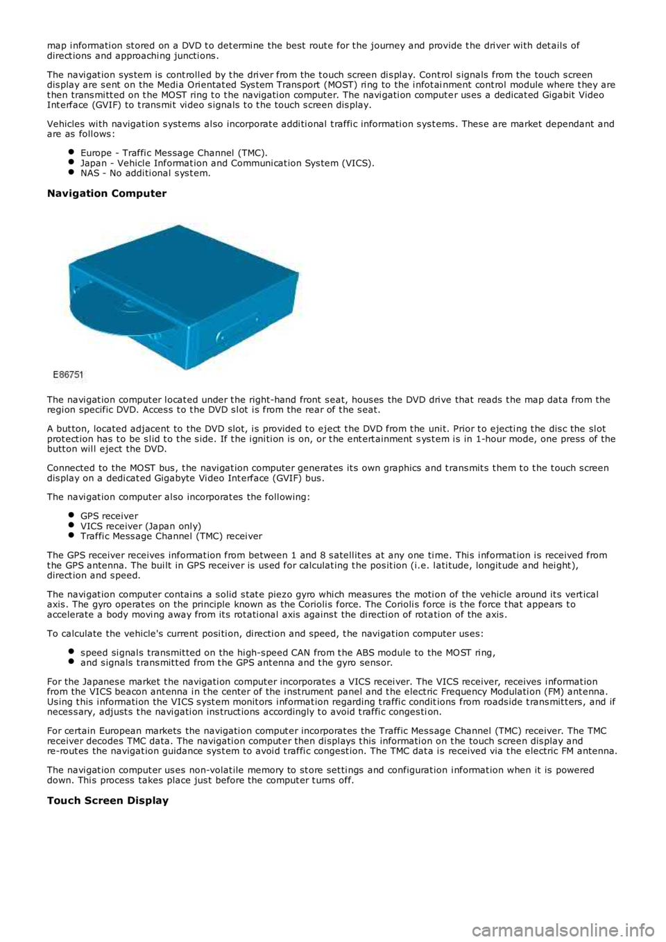
map i nformati on st ored on a DVD t o det ermi ne the bes t rout e for t he journey and provide t he dri ver wi th det ail s ofdirect ions and approachi ng juncti ons .
The navi gat ion sys tem is cont roll ed by t he dri ver from the t ouch screen di s pl ay. Cont rol s ignals from the touch s creendis play are s ent on the Medi a Ori entat ed Sys t em Trans port (MOST) ri ng to the i nfot ainment cont rol module where t hey aret hen trans mi tt ed on t he MOST ring t o t he navi gati on comput er. The navi gati on comput er us es a dedicat ed Gigabit VideoInt erface (GVIF) to t rans mi t vi deo s ignals t o t he touch s creen dis play.
Vehicles wi th navigat ion s yst ems al so incorporat e addi ti onal t raffi c informati on s yst ems . Thes e are market dependant andare as foll ows :
Europe - Traffi c Mes sage Channel (TMC).Japan - Vehicl e Informat ion and Communi cat ion Sys tem (VICS).NAS - No addi ti onal s ys t em.
Navigation Computer
The navi gat ion comput er l ocat ed under t he right-hand front s eat, hous es the DVD dri ve that reads t he map dat a from theregi on specific DVD. Acces s t o t he DVD s l ot i s from the rear of t he s eat.
A but ton, located adjacent to the DVD s lot, i s provided t o eject t he DVD from t he uni t. Prior t o ejecti ng t he dis c the sl otprot ect ion has t o be s l id t o t he s ide. If t he i gni ti on is on, or t he ent ert ainment sys t em i s in 1-hour mode, one press of t hebutt on wil l eject the DVD.
Connected to the MOST bus , t he navi gat ion computer generat es it s own graphics and t rans mit s t hem t o t he t ouch s creendis play on a dedi cat ed Gigabyte Vi deo Int erface (GVIF) bus .
The navi gat ion comput er al so incorporat es the foll owing:
GPS receiverVICS receiver (Japan onl y)Traffi c Mess age Channel (TMC) recei ver
The GPS receiver receives informat ion from between 1 and 8 s atell it es at any one ti me. Thi s i nformat ion i s received fromt he GPS antenna. The bui lt in GPS receiver is us ed for calculat ing t he pos it ion (i.e. l ati tude, longit ude and hei ght ),direct ion and s peed.
The navi gat ion comput er contai ns a s olid s tat e piezo gyro whi ch measures the moti on of the vehicle around it s vert icalaxis . The gyro operat es on the principle known as the Corioli s force. The Corioli s force is t he force t hat appears t oaccelerate a body movi ng away from it s rot ati onal axis agains t the di recti on of rot ati on of the axis .
To calculate the vehicle's current posi ti on, di recti on and s peed, t he navi gat ion computer us es:
s peed si gnal s transmit ted on the hi gh-s peed CAN from t he ABS module to the MO ST ri ng,and s ignals t rans mit t ed from t he GPS ant enna and t he gyro sens or.
For the Japanes e market t he navigati on comput er incorporates a VICS recei ver. The VICS receiver, receives i nformat ionfrom the VICS beacon ant enna i n t he cent er of the i nst rument panel and t he elect ric Frequency Modulati on (FM) ant enna.Us ing t his i nformati on the VICS s yst em monit ors i nformat ion regarding t raffi c conditions from roads ide t rans mit t ers , and ifneces s ary, adjust s t he navi gati on ins truct ions accordingly t o avoid t raffi c conges tion.
For certain European markets the navigati on comput er incorporat es the Traffic Mes s age Channel (TMC) receiver. The TMCreceiver decodes TMC data. The navigati on comput er then di spl ays t his informati on on t he touch s creen dis play andre-rout es the navigat ion guidance sys t em t o avoi d t raffi c congest ion. The TMC dat a is received via t he electric FM antenna.
The navi gat ion comput er us es non-volat ile memory to st ore set ti ngs and configurat ion i nformat ion when it is powereddown. Thi s process takes place jus t before the comput er t urns off.
Touch Screen Display
Page 1920 of 3229
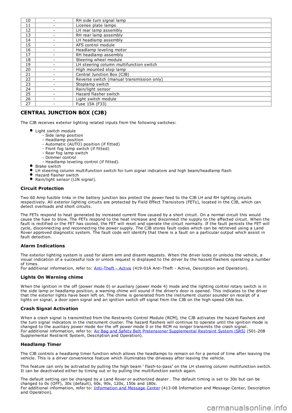
10-RH s i de turn s ignal lamp
11-Licens e pl ate lamps
12-LH rear l amp as s embl y13-RH rear lamp as s embly
14-LH headlamp as s embly
15-AFS cont rol module16-Headl amp l evel ing mot or
17-RH headlamp as s embly
18-Steering wheel modul e19-LH s t eering column mult ifunct ion s wit ch
20-High mount ed s top lamp
21-Central Junct ion Box (CJB)22-Revers e s wit ch (manual transmis si on only)
23-Stoplamp s wit ch
24-Rain/light s ensor25-Hazard flas her s wi tch
26-Light s wit ch modul e
27-Fuse 15A (F33)
CENTRAL JUNCTION BOX (CJB)
The CJB receives exteri or li ght ing relat ed inputs from t he fol lowing s wi tches:
Light s wit ch modul e- Side l amp pos it ion- Headlamp pos it ion- Automat ic (AUTO) posi ti on (if fi tt ed)- Front fog lamp swi tch (if fit ted)- Rear fog l amp s wit ch- Dimmer cont rol- Headlamp l evel ing control (if fit ted).Brake s wi tchLH s t eering column mult ifunct ion s wit ch for t urn si gnal i ndi cat ors and hi gh beam/headl amp flas hHazard flas her s wi tchRain/light s ensor (LIN si gnal ).
Circuit Protection
Two 60 Amp fus ibl e li nks in t he batt ery junct ion box protect the power feed to the CJB LH and RH li ght ing ci rcuit sres pect ively. All ext erior l ighti ng ci rcuit s are prot ect ed by Field Effect Trans is t ors (FETs ), l ocat ed in the CJB, which candetect overloads and s hort circuit s .
The FETs res pond to heat generated by increased current fl ow caus ed by a s hort ci rcuit . On a normal ci rcuit t his woul dcaus e t he fus e to bl ow. The FETs respond t o t he heat i ncrease and di s connect t he s uppl y t o t he affect ed ci rcuit . W hen t hefaul t is rect ified or t he FET has cool ed, t he FET wil l res et and operate t he circui t normall y. If t he faul t pers is ts the FET wi llcycle, di sconnect ing and reconnect ing t he power supply. The CJB s tores fault codes which can be ret rieved usi ng a LandRover approved diagnost ic sys tem. The fault code wil l identi fy t hat there is a fault on a part icular out put which as si s t infaul t det ect ion.
Alarm Indications
The exteri or li ght ing s ys tem is us ed for al arm arm and dis arm reques ts . W hen t he driver l ocks or unlocks the vehicle, avis ual i ndicat ion of a s uccess ful l ock or unlock reques t is di spl ayed t o t he dri ver by the hazard flas hers operat ing a numberof ti mes .For addit ional informat ion, refer t o: Anti -Theft - Act ive (419-01A Anti -Theft - Acti ve, Des cri pt ion and Operati on).
Lights On Warning chime
W hen t he i gni ti on in the off (power mode 0) or auxi liary (power mode 4) mode and the l ighti ng cont rol rotary swit ch is i nt he si de lamp or headlamp posi ti on, a warning chime wi ll s ound i f the driver's door is opened. This indicates t o t he dri vert hat t he exterior li ght s have been left on. The chime is generat ed from t he i ns t rument clus ter s ounder on receipt of ali ght s on s i gnal , a door open s ignal and an ignit ion swi tch off s ignal from t he CJB on the hi gh s peed CAN bus.
Crash Signal Activation
W hen a crash s ignal i s t rans mit ted from t he Rest rai nts Cont rol Modul e (RCM), t he CJB act ivat es the hazard flas hers andt he turn s ignal indicators in t he i ns t rument clus ter. The hazard fl ashers wil l continue to operate unt il t he ignit ion mode ischanged t o t he auxi liary power mode 4or the off power mode 0 or the RCM no longer trans mi ts the cras h si gnal .For addit ional informat ion, refer t o: Air Bag and Safet y Belt Pretens ioner Supplement al Res traint Syst em (SRS) (501-20BSuppl ement al Rest rai nt Sys tem, Des cri pti on and Operati on).
Headlamp Timer
The CJB cont rol s a headl amp t imer funct ion whi ch allows the headlamps t o remain on for a peri od of ti me after leaving t hevehi cl e. Thi s is a dri ver conveni ence feat ure which il lumi nat es t he dri veway after leaving t he vehicle.
This feat ure can onl y be acti vat ed by pulli ng t he high beam ' flas h-t o-pas s' on t he LH s t eering column mult ifunct ion s wi tch.It can be deacti vat ed eit her by ti ming out or by pull ing t he mul ti funct ion swi tch again.
The default s ett ing can be changed by a Land Rover or authorized deal er . The default t imi ng is s et t o 30s but can bechanged t o 0s (OFF), 30s (defaul t), 60s , 90s , 120s , 150s and 180s .For addit ional informat ion, refer t o: Informat ion and Mes s age Cent er (413-08 Informat ion and Mes s age Cent er, Des cript ionand Operat ion).