2006 LAND ROVER FRELANDER 2 blower
[x] Cancel search: blowerPage 60 of 3229
DT CDescriptionPossible CausesAction
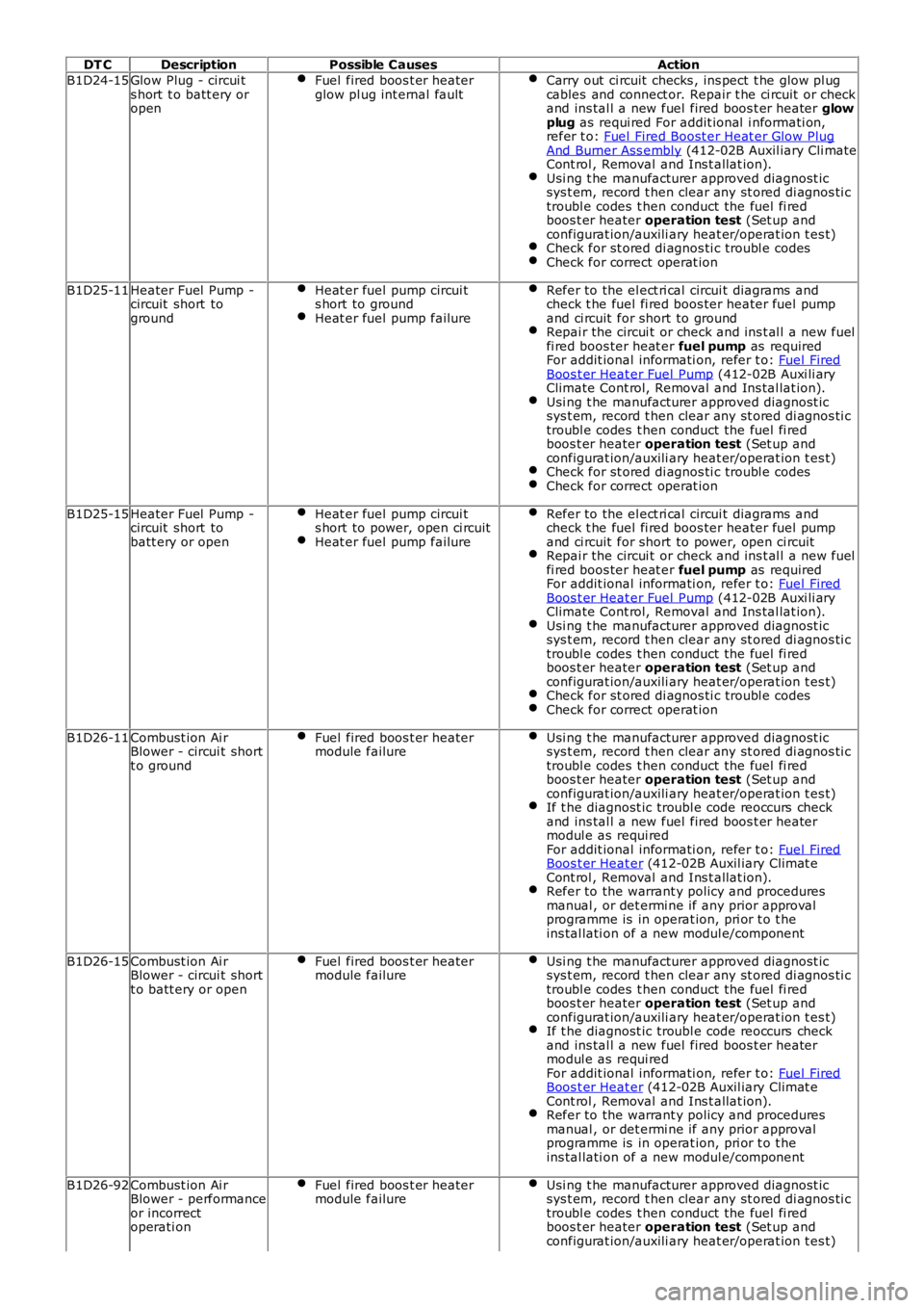
B1D24-15Glow Plug - circui ts hort t o batt ery oropen
Fuel fired boos t er heaterglow pl ug int ernal faultCarry out ci rcuit checks , ins pect t he glow pl ugcables and connect or. Repair t he ci rcuit or checkand ins tal l a new fuel fired boos t er heater glowplug as requi red For addit ional i nformati on,refer t o: Fuel Fired Boost er Heat er Glow PlugAnd Burner Ass embly (412-02B Auxil iary Cli mateCont rol , Removal and Ins t allat ion).Usi ng t he manufacturer approved diagnost icsys t em, record t hen clear any st ored di agnos ti ctroubl e codes t hen conduct the fuel fi redboos t er heater operation test (Set up andconfigurat ion/auxili ary heat er/operat ion t es t)Check for st ored di agnos ti c troubl e codesCheck for correct operat ion
B1D25-11Heater Fuel Pump -circuit short toground
Heat er fuel pump circui ts hort to groundHeat er fuel pump failure
Refer to the el ect ri cal circui t diagrams andcheck t he fuel fi red boos ter heater fuel pumpand ci rcuit for short to groundRepai r the circui t or check and ins t al l a new fuelfi red boos ter heat er fuel pump as requiredFor addit ional informati on, refer t o: Fuel FiredBoos t er Heat er Fuel Pump (412-02B Auxi li aryClimate Cont rol, Removal and Ins tal lat ion).Usi ng t he manufacturer approved diagnost icsys t em, record t hen clear any st ored di agnos ti ctroubl e codes t hen conduct the fuel fi redboos t er heater operation test (Set up andconfigurat ion/auxili ary heat er/operat ion t es t)Check for st ored di agnos ti c troubl e codesCheck for correct operat ion
B1D25-15Heater Fuel Pump -circuit short tobatt ery or open
Heat er fuel pump circui ts hort to power, open ci rcuitHeat er fuel pump failure
Refer to the el ect ri cal circui t diagrams andcheck t he fuel fi red boos ter heater fuel pumpand ci rcuit for short to power, open ci rcuitRepai r the circui t or check and ins t al l a new fuelfi red boos ter heat er fuel pump as requiredFor addit ional informati on, refer t o: Fuel FiredBoos t er Heat er Fuel Pump (412-02B Auxi li aryClimate Cont rol, Removal and Ins tal lat ion).Usi ng t he manufacturer approved diagnost icsys t em, record t hen clear any st ored di agnos ti ctroubl e codes t hen conduct the fuel fi redboos t er heater operation test (Set up andconfigurat ion/auxili ary heat er/operat ion t es t)Check for st ored di agnos ti c troubl e codesCheck for correct operat ion
B1D26-11Combust ion Ai rBlower - circui t shortt o ground
Fuel fired boos t er heatermodule failureUsi ng t he manufacturer approved diagnost icsys t em, record t hen clear any st ored di agnos ti ctroubl e codes t hen conduct the fuel fi redboos t er heater operation test (Set up andconfigurat ion/auxili ary heat er/operat ion t es t)If t he diagnost ic troubl e code reoccurs checkand ins tal l a new fuel fired boos t er heatermodul e as requi redFor addit ional informati on, refer t o: Fuel FiredBoos t er Heat er (412-02B Auxil iary Climat eCont rol , Removal and Ins t allat ion).Refer to the warrant y policy and proceduresmanual , or det ermi ne if any prior approvalprogramme is in operat ion, pri or t o t heins tal lati on of a new modul e/component
B1D26-15Combust ion Ai rBlower - circui t shortt o batt ery or open
Fuel fired boos t er heatermodule failureUsi ng t he manufacturer approved diagnost icsys t em, record t hen clear any st ored di agnos ti ctroubl e codes t hen conduct the fuel fi redboos t er heater operation test (Set up andconfigurat ion/auxili ary heat er/operat ion t es t)If t he diagnost ic troubl e code reoccurs checkand ins tal l a new fuel fired boos t er heatermodul e as requi redFor addit ional informati on, refer t o: Fuel FiredBoos t er Heat er (412-02B Auxil iary Climat eCont rol , Removal and Ins t allat ion).Refer to the warrant y policy and proceduresmanual , or det ermi ne if any prior approvalprogramme is in operat ion, pri or t o t heins tal lati on of a new modul e/component
B1D26-92Combust ion Ai rBlower - performanceor incorrectoperati on
Fuel fired boos t er heatermodule failureUsi ng t he manufacturer approved diagnost icsys t em, record t hen clear any st ored di agnos ti ctroubl e codes t hen conduct the fuel fi redboos t er heater operation test (Set up andconfigurat ion/auxili ary heat er/operat ion t es t)
Page 61 of 3229
DT CDescriptionPossible CausesAction
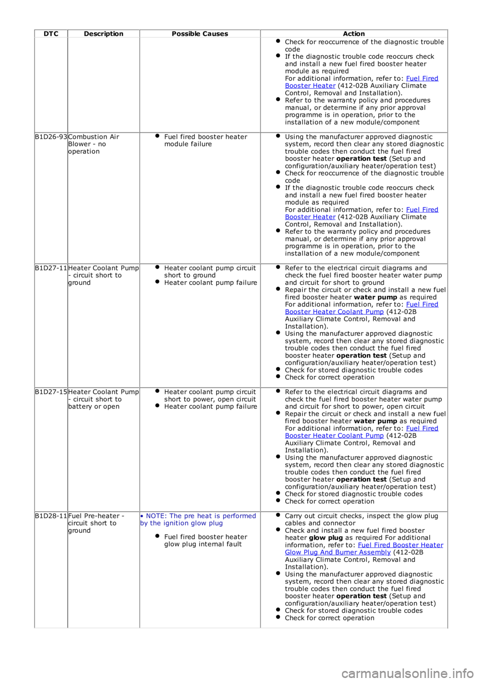
Check for reoccurrence of t he diagnost ic troubl ecodeIf t he diagnost ic troubl e code reoccurs checkand ins tal l a new fuel fired boos t er heatermodul e as requi redFor addit ional informati on, refer t o: Fuel FiredBoos t er Heat er (412-02B Auxil iary Climat eCont rol , Removal and Ins t allat ion).Refer to the warrant y policy and proceduresmanual , or det ermi ne if any prior approvalprogramme is in operat ion, pri or t o t heins tal lati on of a new modul e/component
B1D26-93Combust ion Ai rBlower - nooperati on
Fuel fired boos t er heatermodule failureUsi ng t he manufacturer approved diagnost icsys t em, record t hen clear any st ored di agnos ti ctroubl e codes t hen conduct the fuel fi redboos t er heater operation test (Set up andconfigurat ion/auxili ary heat er/operat ion t es t)Check for reoccurrence of t he diagnost ic troubl ecodeIf t he diagnost ic troubl e code reoccurs checkand ins tal l a new fuel fired boos t er heatermodul e as requi redFor addit ional informati on, refer t o: Fuel FiredBoos t er Heat er (412-02B Auxil iary Climat eCont rol , Removal and Ins t allat ion).Refer to the warrant y policy and proceduresmanual , or det ermi ne if any prior approvalprogramme is in operat ion, pri or t o t heins tal lati on of a new modul e/component
B1D27-11Heater Coolant Pump- circui t short toground
Heat er cool ant pump ci rcuits hort to groundHeat er cool ant pump fail ure
Refer to the el ect ri cal circui t diagrams andcheck t he fuel fi red boos ter heater water pumpand ci rcuit for short to groundRepai r the circui t or check and ins t al l a new fuelfi red boos ter heat er water pump as requi redFor addit ional informati on, refer t o: Fuel FiredBoos t er Heat er Cool ant Pump (412-02BAuxi liary Cli mate Cont rol , Removal andIns tal lat ion).Usi ng t he manufacturer approved diagnost icsys t em, record t hen clear any st ored di agnos ti ctroubl e codes t hen conduct the fuel fi redboos t er heater operation test (Set up andconfigurat ion/auxili ary heat er/operat ion t es t)Check for st ored di agnos ti c troubl e codesCheck for correct operat ion
B1D27-15Heater Coolant Pump- circui t short tobatt ery or open
Heat er cool ant pump ci rcuits hort to power, open ci rcuitHeat er cool ant pump fail ure
Refer to the el ect ri cal circui t diagrams andcheck t he fuel fi red boos ter heater water pumpand ci rcuit for short to power, open ci rcuitRepai r the circui t or check and ins t al l a new fuelfi red boos ter heat er water pump as requi redFor addit ional informati on, refer t o: Fuel FiredBoos t er Heat er Cool ant Pump (412-02BAuxi liary Cli mate Cont rol , Removal andIns tal lat ion).Usi ng t he manufacturer approved diagnost icsys t em, record t hen clear any st ored di agnos ti ctroubl e codes t hen conduct the fuel fi redboos t er heater operation test (Set up andconfigurat ion/auxili ary heat er/operat ion t es t)Check for st ored di agnos ti c troubl e codesCheck for correct operat ion
B1D28-11Fuel Pre-heater -circuit short toground
• NOTE: The pre heat i s performedby the ignit ion gl ow plug
Fuel fired boos t er heaterglow pl ug int ernal fault
Carry out ci rcuit checks , ins pect t he glow pl ugcables and connect orCheck and i ns t all a new fuel fi red boost erheat er glow plug as requi red For addi ti onalinformati on, refer t o: Fuel Fired Boos t er Heat erGlow Pl ug And Burner As sembl y (412-02BAuxi liary Cli mate Cont rol , Removal andIns tal lat ion).Usi ng t he manufacturer approved diagnost icsys t em, record t hen clear any st ored di agnos ti ctroubl e codes t hen conduct the fuel fi redboos t er heater operation test (Set up andconfigurat ion/auxili ary heat er/operat ion t es t)Check for st ored di agnos ti c troubl e codesCheck for correct operat ion
Page 106 of 3229
DT CDescriptionPossible CauseAction
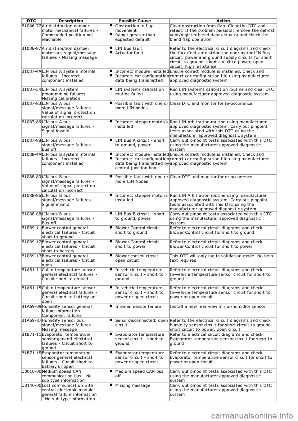
B1086-77Air dis t ri but ion dampermot or mechanical fail ures -Commanded pos i ti on notreachabl e
Obs truct ion i n flapmovementRange greater t hanexpected defaul t
Cl ear obs truct ion from fl ap. Cl ear the DTC andretes t. If the problem pers is ts , remove the defros tvent/regis t er bl end door actuat or and check theblend flap operat ion
B1086-87Air dis t ri but ion dampermot or bus s ignal/mes s agefai lures - Mis s ing mes s age
LIN Bus faultAct uator faul tRefer t o t he electrical ci rcuit diagrams and checkt he face/feet ai r dis tribut ion door motor LIN Buscircui t, power and ground s uppl y circuit s for shortcircui t to ground, s hort circui t t o power, opencircui t, hi gh res is t anceB1087-4ALIN bus A s yst em i nternalfai lures - Incorrectcomponent ins tal led
Incorrect modul e ins tal ledIncorrect car configurat iondata bei ng trans mi tt ed
Ens ure correct modul e is ins tall ed. Check andcorrect car configurat ion fil e usi ng manufacturerapproved diagnost ic s ys tem
B1087-54LIN bus A s yst emprogramming failures -Mis s ing cali brat ion
LIN sys t ems cal ibrat ionrout ine failedRun LIN s yst ems cali brati on rout ine and clear DTCus ing manufact urer approved di agnos t ic s yst em
B1087-83LIN bus A buss ignal/mess age fai lures -Value of s ignal protecti oncal cul ati on incorrect
Poss ibl e faul t wit h one ormore LIN nodesCl ear DTC and moni tor for re-occurrence
B1087-86LIN bus A buss ignal/mess age fai lures -Signal inval id
Incorrect s t epper mot or/sins tal ledRun LIN Arbi trati on rout ine us ing manufact urerapproved diagnost ic s ys tem. Carry out pinpointt est s as s ociat ed wi th t his DTC usi ng t hemanufact urer approved di agnos ti c s ys t emB1087-88LIN bus A buss ignal/mess age fai lures -Bus off
LIN Bus A circui t - s hortto ground, powerCarry out pinpoint t es t s as sociat ed wit h t his DTCus ing t he manufacturer approved di agnos ti cs yst em
B1088-4ALIN bus B s yst em i nternalfai lures - Incorrectcomponent ins tal led
Incorrect modul e ins tal ledIncorrect car configurat iondata bei ng trans mi tt ed bycent ral juncti on box
Ens ure correct modul e is ins tall ed. Check andcorrect car configurat ion fil e usi ng manufacturerapproved diagnost ic s ys tem
B1088-83LIN bus B buss ignal/mess age fai lures -Value of s ignal protecti oncal cul ati on incorrect
Poss ibl e faul t wit h one ormore LIN NodesCl ear DTC and moni tor for re-occurrence
B1088-86LIN bus B buss ignal/mess age fai lures -Signal inval id
Incorrect s t epper mot or/sins tal ledRun LIN Arbi trati on rout ine us ing manufact urerapproved diagnost ic s ys tem. Carry out pinpointt est s as s ociat ed wi th t his DTC usi ng t hemanufact urer approved di agnos ti c s ys t em
B1088-88LIN bus B buss ignal/mess age fai lures -Bus off
LIN Bus B circui t - s hortto ground, powerCarry out pinpoint t es t s as sociat ed wit h t his DTCus ing t he manufacturer approved di agnos ti cs yst emB10B9-11Blower cont rol generalelectrical fail ures - Ci rcuits hort to ground
Blower Control circui t -s hort to groundRefer t o elect rical circuit di agrams and checkBl ower Control ci rcuit for short to ground
B10B9-12Blower cont rol generalelectrical fail ures - Ci rcuits hort to bat t ery
Blower Control circui t -s hort to powerRefer t o elect rical circuit di agrams and checkBl ower Control ci rcuit for short to power
B10B9-13Blower cont rol generalelectrical fail ures - Ci rcuitopen
Blower cont rol circui t -open ci rcuitThis DTC wil l onl y log in vali dat ion mode. No hel pt ext requi red
B1A61-11Cabi n t emperature s ensorgeneral el ect ri cal fai lures -Circui t short to ground
In-vehi cl e t emperatures ens or circuit - short toground
Refer t o elect rical circuit di agrams and checkIn-vehicle t emperat ure s ens or circui t for s hort t oground
B1A61-15Cabi n t emperature s ensorgeneral el ect ri cal fai lures -Circui t short to bat tery oropen
In-vehi cl e t emperatures ens or circuit - short topower or open circui t
Refer t o elect rical circuit di agrams and checkIn-vehicle t emperat ure s ens or circui t for s hort t opower or open ci rcuit
B1A69-09Humidi ty s ens or generalfai lure informati on -Component fai lures
Int ernal s ens or fai lureInst all a new rear view mirror/humidi ty s ens or
B1A69-87Humidi ty s ens or buss ignal/mess age fai lures -Mis s ing mess age
Senor dis connected, opencircuitRefer t o t he electrical ci rcuit diagrams and checkhumi di ty sens or ci rcuit for short ci rcuit t o ground,s hort circui t to power, open ci rcuit
B1B71-11Evaporat or temperat ures ens or general el ect ri calfai lures - Ci rcuit s hort t oground
Evaporat or temperat ures ens or circuit - short toground
Refer t o elect rical circuit di agrams and checkEvaporator t emperature s ens or circuit for s hort toground
B1B71-15Evaporat or temperat ures ens or general el ect ri calfai lures - Ci rcuit s hort t obatt ery or open
Evaporat or temperat ures ens or circuit - short topower or open circui t
Refer t o elect rical circuit di agrams and checkEvaporator t emperature s ens or circuit for s hort topower or open ci rcuit
U0010-00Medium speed CANcommunicat ion bus - Nos ub type i nformat ion
Medium speed CAN busoffCarry out pinpoint t es t s as sociat ed wit h t his DTCus ing t he manufacturer approved di agnos ti cs yst em
U0140-00Los t communicati on wi thcent ral electronic modulegeneral fail ure i nformat ion- No s ub t ype informati on
Mis s ing mess ageCarry out pinpoint t es t s as sociat ed wit h t his DTCus ing t he manufacturer approved di agnos ti cs yst em
Page 1629 of 3229
Publi shed: 06-Jul-2011
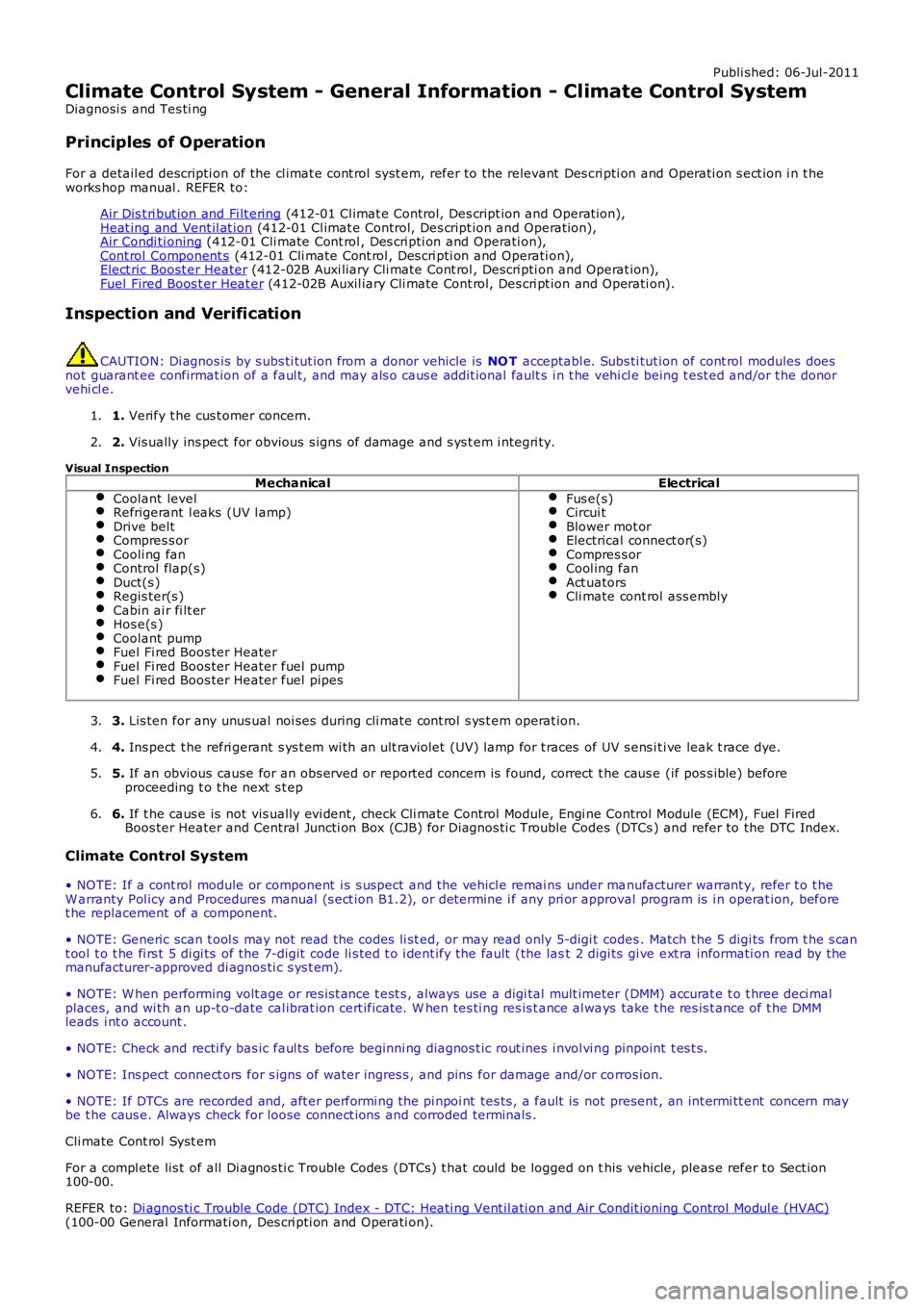
Climate Control System - General Information - Climate Control System
Diagnosi s and Tes ti ng
Principles of Operation
For a detail ed descripti on of the cl imat e cont rol s yst em, refer to the relevant Des cri pti on and Operati on s ect ion i n t heworks hop manual . REFER to:
Air Dis t ri but ion and Fi lt ering (412-01 Cl imat e Control, Des cript ion and Operat ion),Heat ing and Vent il at ion (412-01 Cl imat e Control, Des cript ion and Operat ion),Air Condi ti oning (412-01 Cli mate Cont rol , Des cri pti on and Operati on),Cont rol Component s (412-01 Cli mate Cont rol , Des cri pti on and Operati on),Elect ric Boost er Heater (412-02B Auxi liary Cli mate Cont rol , Descri pti on and Operat ion),Fuel Fired Boos t er Heat er (412-02B Auxil iary Cli mate Cont rol, Des cri pt ion and Operati on).
Inspection and Verification
CAUTION: Di agnos is by s ubs ti tut ion from a donor vehicle is NO T acceptabl e. Subs ti tut ion of cont rol modules doesnot guarant ee confirmat ion of a faul t, and may als o caus e addit ional fault s i n t he vehi cl e being t est ed and/or t he donorvehi cl e.
1. Verify t he cus t omer concern.1.
2. Vis ually ins pect for obvious s igns of damage and s ys t em i ntegri ty.2.
Visual InspectionMechanicalElectrical
Coolant levelRefrigerant l eaks (UV l amp)Drive beltCompres s orCooli ng fanControl flap(s)Duct(s )Regis ter(s )Cabin ai r fi lt erHos e(s )Coolant pumpFuel Fi red Boos ter HeaterFuel Fi red Boos ter Heater fuel pumpFuel Fi red Boos ter Heater fuel pipes
Fus e(s)Circui tBlower mot orElectrical connect or(s)Compres s orCool ing fanAct uatorsCli mate cont rol ass embly
3. Lis ten for any unus ual noi ses during cli mate cont rol s ys t em operat ion.3.
4. Ins pect t he refri gerant s ys t em wi th an ult raviolet (UV) lamp for t races of UV s ens i ti ve leak t race dye.4.
5. If an obvious cause for an obs erved or report ed concern is found, correct t he caus e (if pos s ible) beforeproceeding t o t he next s t ep5.
6. If t he caus e is not vis ually evi dent , check Cli mate Cont rol Module, Engi ne Control Module (ECM), Fuel FiredBoos ter Heater and Central Juncti on Box (CJB) for Di agnos ti c Trouble Codes (DTCs ) and refer to the DTC Index.6.
Climate Control System
• NOTE: If a cont rol module or component i s s uspect and the vehicl e remai ns under manufacturer warrant y, refer t o t heW arranty Pol icy and Procedures manual (s ect ion B1.2), or determine i f any pri or approval program is i n operat ion, beforet he replacement of a component.
• NOTE: Generic scan t ool s may not read the codes li st ed, or may read only 5-digi t codes . Match t he 5 digi ts from t he s cant ool t o t he fi rs t 5 di gi ts of the 7-digit code li s ted t o i dent ify the fault (the last 2 digi ts gi ve ext ra informati on read by themanufacturer-approved di agnos ti c s ys t em).
• NOTE: W hen performing volt age or res is t ance t est s , always use a digi tal mult imeter (DMM) accurat e t o t hree deci malplaces, and wi th an up-t o-date cal ibrat ion cert ificate. W hen tes ti ng res is t ance al ways take t he res is t ance of t he DMMleads i nt o account .
• NOTE: Check and recti fy bas ic faul ts before beginni ng diagnos t ic rout ines i nvol vi ng pinpoint t es t s.
• NOTE: Ins pect connect ors for s igns of water ingres s , and pins for damage and/or corros ion.
• NOTE: If DTCs are recorded and, aft er performi ng the pi npoi nt tes ts , a fault is not present , an int ermi tt ent concern maybe t he caus e. Always check for loose connect ions and corroded terminals .
Cli mate Cont rol Syst em
For a compl ete lis t of all Di agnos ti c Trouble Codes (DTCs) t hat could be logged on this vehicle, pleas e refer to Sect ion100-00.
REFER to: Di agnos ti c Trouble Code (DTC) Index - DTC: Heati ng Vent il ati on and Air Condit ioning Control Modul e (HVAC)(100-00 General Informati on, Des cri pti on and Operati on).
Page 1635 of 3229
Publi s hed: 11-May-2011
Climate Control - Heating and Ventilation
Des cript ion and Operat ion
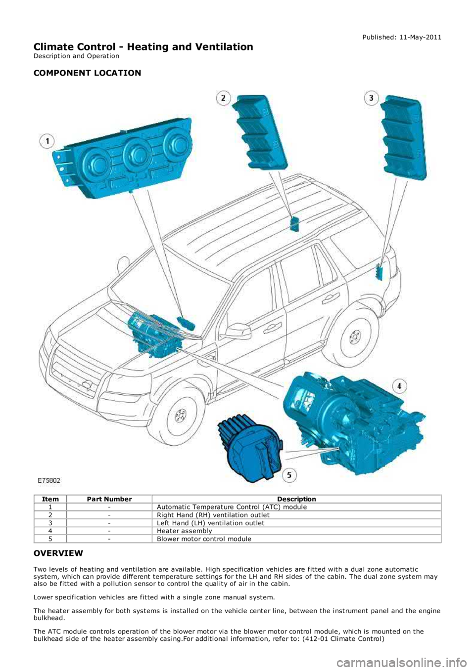
COMPONENT LOCATION
ItemPart NumberDescription1-Automat ic Temperat ure Cont rol (ATC) modul e
2-Right Hand (RH) vent il at ion out let
3-Left Hand (LH) vent il at ion out let4-Heater as s embl y
5-Blower mot or cont rol module
OVERVIEW
Two l evels of heat ing and venti lati on are avai lable. High s pecifi cat ion vehicles are fit ted wit h a dual zone aut omati cs ys t em, which can provide di fferent temperature s et t ings for t he LH and RH si des of the cabin. The dual zone s yst em mayals o be fit t ed wit h a pol luti on s ens or t o cont rol t he qual it y of air in the cabin.
Lower s pecifi cat ion vehicles are fit ted wit h a s ingle zone manual s yst em.
The heat er ass embl y for both sys t ems is ins tall ed on t he vehi cl e cent er li ne, bet ween the i nst rument panel and the enginebulkhead.
The ATC module cont rols operat ion of t he blower mot or vi a t he blower mot or control modul e, whi ch is mount ed on t hebulkhead si de of the heat er as s embly cas ing.For addi ti onal i nformat ion, refer to: (412-01 Cli mate Cont rol )
Page 1636 of 3229
Air Dis t ri but ion and Fi lt ering (Des cript ion and Operat ion),Air Condi ti oning (Descri pti on and Operat ion),Cont rol Component s (Descri pti on and Operat ion).
Some vehicles may al s o be fit ted wi th an auxi li ary heater. For addit ional i nformati on, refer t o: (412-02B Auxil iary Cl imat eControl )
Elect ric Boost er Heater (Des cri pti on and Operati on),Fuel Fired Boos t er Heat er (Des cript ion and O perati on).
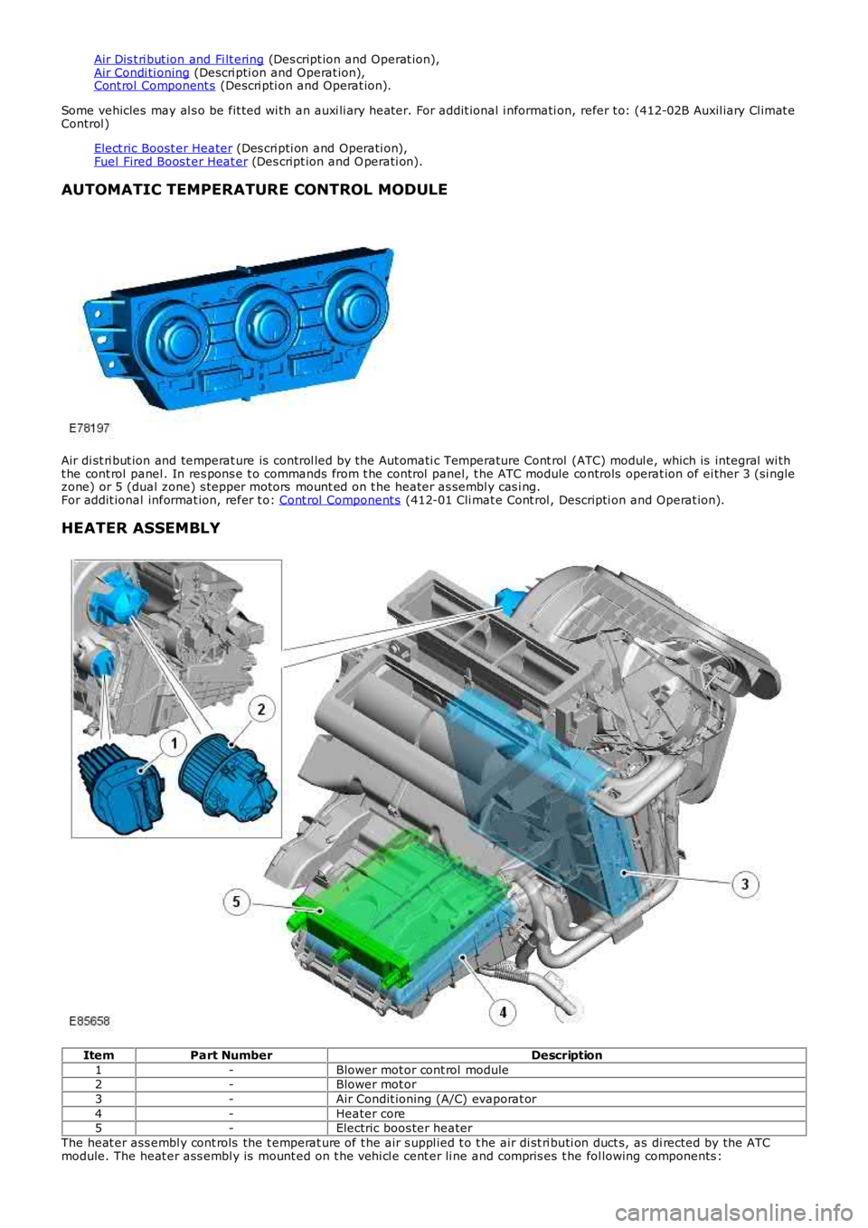
AUTOMATIC TEMPERATURE CONTROL MODULE
Air di st ri but ion and temperat ure is control led by the Aut omati c Temperature Cont rol (ATC) modul e, which is integral wi tht he cont rol panel . In res pons e t o commands from t he control panel, t he ATC module controls operat ion of ei ther 3 (si nglezone) or 5 (dual zone) s tepper motors mount ed on t he heater as sembl y cas i ng.For addit ional informat ion, refer t o: Cont rol Component s (412-01 Cli mat e Cont rol , Descripti on and Operat ion).
HEATER ASSEMBLY
ItemPart NumberDescription
1-Blower mot or cont rol module2-Blower mot or
3-Air Condit ioning (A/C) evaporat or
4-Heater core5-Electric boos ter heater
The heat er ass embl y cont rols the t emperat ure of t he air s uppl ied t o t he air di st ri buti on duct s, as di rected by the ATCmodule. The heat er ass embl y is mount ed on t he vehi cl e cent er li ne and compris es t he fol lowing components :
Page 1637 of 3229
Blower mot orHeater coreCabin ai r fil ter.For addit ional informat ion, refer t o: Air Di st ri buti on and Fi lt eri ng (412-01 Climat e Cont rol, Des cript ion andOperat ion).A/C evaporat or.For addit ional informat ion, refer t o: Air Condit ioning (412-01 Cli mat e Cont rol , Descripti on and Operat ion).Air i ntake flap and s tepper motor.For addit ional informat ion, refer t o: Cont rol Component s (412-01 Cli mat e Cont rol , Descripti on and Operat ion).Air di st ri but ion fl aps and s t epper mot ors .For addit ional informat ion, refer t o: Cont rol Component s (412-01 Cli mat e Cont rol , Descripti on and Operat ion).Temperature blend flaps and s t epper mot ors .For addit ional informat ion, refer t o: Cont rol Component s (412-01 Cli mat e Cont rol , Descripti on and Operat ion).Electric boos ter heater (if fi tt ed).For addit ional informat ion, refer t o: Electric Boos ter Heater (412-02 Auxi li ary Cl imat e Control, Des cript ion andOperat ion).
Blower Motor
The blower mot or compris es an open hub, centrifugal fan powered by an elect ric motor. Operati on of the bl ower motor iscont rol led by t he ATC module in conjuncti on wit h t he blower mot or control modul e. The ATC module provi des a Puls e W i dthModulated (PW M) si gnal t o t he blower motor control modul e based on the requi red bl ower speed. The bl ower motor cont rolmodule i nterprets the PW M s ignal as a blower mot or speed and controls t he volt age to t he blower mot or accordingl y.For addit ional informat ion, refer t o: Cont rol Component s (412-01 Cli mat e Cont rol , Descripti on and Operat ion).
Heater Core
The heat er core provi des t he heat s ource to warm the ai r bei ng s uppl ied i nto t he cabin. The heat er core is an alumi num, 2pass , fin and t ube heat exchanger ins t al led acros s t he widt h of t he heat er ass embly. Two al uminum tubes att ached t o t heheat er core extend t hrough t he engi ne bulkhead and connect t o t he engine cool ing s ystem. W hen the engine is runni ng,engi ne cool ant is const antl y ci rculat ed through the heater core by the coolant pump. For addit ional informati on, refer t o:
Engi ne Cool ing (303-03A Engine Cooli ng - I6 3.2L Petrol, Des cript ion and Operat ion),Engi ne Cool ing (303-03B Engine Cooli ng - TD4 2.2L Di esel , Descri pti on and Operat ion).
VENTILATION OUTLETS
The vent il ati on out let s all ow t he free flow of ai r through t he cabi n. The out let s are ins tall ed in the LH and RH rear quart erpanel s, behind the t ail lamps .
Each vent ilat ion out let compri ses a gril le covered by a s oft rubber fl ap, and i s effect ively a non-ret urn val ve. The flapsopen and cl ose aut omat ical ly depending on t he different ial between cabin and out si de air pres s ures .
PRINCIPLES OF OPERATION
Operat ion of t he heat ing and venti lat ion s ys tem is controlled by the ATC modul e.For addit ional informat ion, refer t o: Cont rol Component s (412-01 Cli mat e Cont rol , Descripti on and Operat ion).
Page 1641 of 3229
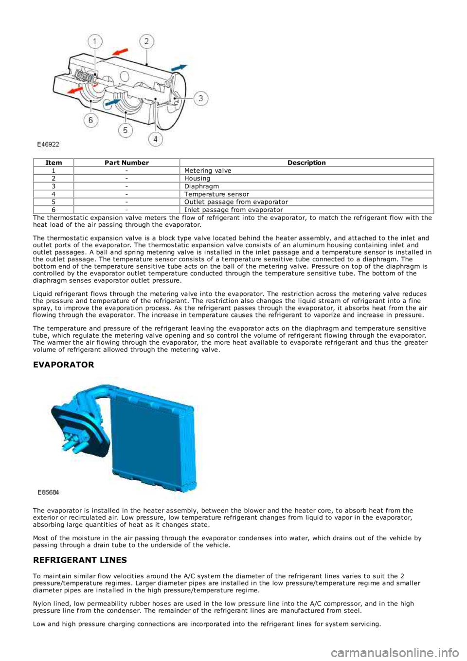
ItemPart NumberDescription
1-Met ering val ve2-Hous ing
3-Di aphragm
4-Temperat ure s ens or5-Out let pass age from evaporat or
6-Inlet pass age from evaporat or
The t hermos tat ic expans ion val ve meters the fl ow of refri gerant i nto the evaporator, to match t he refri gerant fl ow wi th t heheat load of the ai r pas s ing through t he evaporat or.
The t hermos tat ic expans ion val ve is a bl ock type valve l ocat ed behi nd the heat er as sembly, and att ached t o t he inl et andoutl et ports of t he evaporator. The t hermos t at ic expansi on valve cons i st s of an aluminum hous ing containi ng inlet andoutl et pas s ages . A ball and s pri ng met ering val ve is i nst all ed in the i nlet pass age and a t emperat ure s ensor i s ins t al led i nt he out let pas sage. The t emperature s ens or cons is t s of a t emperature s ens i ti ve tube connect ed to a diaphragm. Thebott om end of t he t emperature s ens it ive tube acts on the ball of t he met ering val ve. Pres s ure on top of t he diaphragm iscont rol led by t he evaporat or outl et t emperat ure conduct ed through the t emperat ure s ensi ti ve tube. The bott om of t hediaphragm sens es evaporat or out let pres s ure.
Liquid refrigerant flows t hrough t he metering valve i nto the evaporator. The res trict ion acros s t he metering valve reducest he pres sure and t emperature of the refrigerant . The res trict ion als o changes the l iquid st ream of refrigerant i nto a fi nes pray, to improve t he evaporati on proces s . As t he refri gerant pas s es through the evaporator, it abs orbs heat from t he airfl owing t hrough t he evaporat or. The i ncreas e i n t emperature caus es t he refri gerant to vapori ze and increas e in pres sure.
The t emperature and pres s ure of t he refri gerant l eavi ng the evaporat or act s on t he diaphragm and t emperat ure s ensi ti vet ube, which regul ate the met eri ng val ve openi ng and s o cont rol t he vol ume of refri gerant fl owing t hrough t he evaporat or.The warmer t he air flowi ng through the evaporator, the more heat avai lable to evaporat e refri gerant and thus t he greatervolume of refrigerant all owed through t he met eri ng val ve.
EVAPORATOR
The evaporat or is i nst all ed in the heater as s embly, bet ween t he blower and the heat er core, t o abs orb heat from t heexteri or or recirculat ed air. Low pres s ure, low temperat ure refrigerant changes from li qui d t o vapor i n t he evaporat or,absorbing l arge quant it ies of heat as it changes st ate.
Mos t of the moi s ture in the ai r pas s ing t hrough t he evaporat or condens es i nto wat er, whi ch drains out of the vehicl e bypass i ng through a drain tube t o t he unders ide of t he vehi cl e.
REFRIGERANT LINES
To mai nt ain si mil ar fl ow velocit ies around t he A/C s ys t em t he diamet er of t he refrigerant li nes varies t o s uit t he 2pres s ure/t emperat ure regi mes . Larger di ameter pipes are ins tal led i n t he low pres sure/t emperature regi me and s mall erdiamet er pi pes are i nst all ed in the hi gh pres sure/t emperature regi me.
Nylon l ined, low permeabi li ty rubber hos es are us ed i n t he low press ure li ne int o t he A/C compress or, and i n t he highpres s ure l ine from the condens er. The remainder of the refrigerant l ines are manufact ured from s teel.
Low and high press ure charging connecti ons are i ncorporated i nto the refrigerant li nes for s yst em s ervi ci ng.