2006 LAND ROVER FRELANDER 2 blower
[x] Cancel search: blowerPage 1645 of 3229
7-P ollution sensor (if fi tted)8-W indshie ld distri buti on (defrost) ste pper motor9-Right Hand (RH) tempera ture ble nd s tepper mot or10-Sunload s ens or11-Cabin temperature se nsor12-Automati c Te mpe rature Cont rol (ATC) modul e13-Evaporator te mpe rature s ens or14-Left Hand (LH) te mpe rature blend st eppe r motor15-Blowe r motor control module16-Face/feet dis tribution ste ppe r motor17-Blowe r motor
OVERVIEW
The clima te cont rol s yste m i ncorpora tes the hea ting, ve ntila tion and A/C systems. There are 2 mai n types of clima te controls yste m a vail able ;
a single z one ma nual sys tema dua l zone a utomati c system.
The clima te cont rol f unct ions for bot h systems a re controlle d by the ATC modul e. The ATC module is mounted in the ce nte rcons ole a nd cont ains bot h the syste m e lectronic sof twa re a nd user cont rols .
The ATC module works in conjunction wi th a number of othe r ve hicle control module s, i ncluding the Engine Control Module(ECM), which control s a number of cl ima te control sub-s yste ms on recei pt of reques ts f rom the ATC module .
The s ingle zone climate cont rol s yst em f eat ures ma nual control for air t empera ture , air dist ribution and air source, although as mal l amount of aut oma tic control does exis t in the ATC softwa re. In re sponse to s yste m i nput s, t he ATC module cont rols theopera tion of 3 st epper motors mounted on t he heat er as sembly. The st eppe r motors then a djust the positi on of the ai rt emperat ure, air dist ribution and air source flaps accordingly.
The dual zone cl imat e control system fe atures a utomati c control of air t empera ture , air dis tribution and blower motor s pee d.The ATC module is a lso able to cont rol i ndividua l te mpe rature re que sts for both the dri ver a nd pass enger s ide of the cabin.
• NO TE: The ATC module can only maint ain a maximum tempera ture dif fere nce bet wee n the 2 side s of the cabin of up toa pproximate ly 3ºC (4ºF). This is due to the moveme nt a nd mix of a ir wi thin the cabin.
The dual zone cl imat e control system fe atures 2 additional sens ors; a cabin temperature se nsor and a sunload sensor. Thecabin temperature se nsor provides a temperature fe edback to e nabl e the ATC module s oftware mai ntai n a cons tant ca bint emperat ure. The sunloa d se nsor provide s a rea ding of s ola r loa ding on the vehicle occupants a nd enables the ATC module toa djus t the output from t he clima te control s yste m a ccordingly.
Higher specif icat ion vers ions of t he dual zone cl imat e control system are al so a vailable . These syst ems fea ture 2 morea ddit iona l se nsors; a polluti on s ensor and a cabin humidity sensor.
The pollution sensor det ects pol luta nts ente ring the cabin, allowing the ATC modul e to rea ct by cha ngi ng t he posit ion of thea ir intake fla p. The cabin humidi ty s ensor ca lcul ates the probability of misti ng on the winds hiel d. The ATC module monitorst he s igna l from t he cabin humidi ty s ensor and a djus ts blowe r speed, air dis tribution and A/C compress or di spla cementa ccordingly.
Stop/Start Vehicles - From 2010 MY
To support the Stop/Start system, a number of changes have be en made to the logic and opera tion of climate cont rol s yst emwithi n a Stop/Sta rt cycle to:
maint ain occupant comfortpreve nt winds hie ld mistingconse rve batt ery power.
This has bee n achieved by the ATC (automa tic t emperat ure control) module monitoring and varying when nece ssary, va riousclima te control funct ions wit hin a St op/Start cycle.For a ddit iona l inf ormation, re fer to: Starting Sys tem (303-06C Start ing Syst em - TD4 2.2L Diese l, Vehicles Buil t From:01-03-2009, Des cript ion and Ope rati on).
To maint ain the cabi n te mpe rature when the engine is s hut down in a St op/Start cycle, an a uxil iary electric coolant-pump hasa lso bee n int egra ted into the cooling system to mai ntai n the coolant flow t hrough t he cabi n’s heat er core. The pump isdirectly hardwire d to the ECM. O n ve hicl es fi tted wit h a FFH (fue l fired heat er), the FFH coolant pump i s uti lize d and activa tedvia t he FFH.For a ddit iona l inf ormation, re fer to: Starting Sys tem (303-06C Start ing Syst em - TD4 2.2L Diese l, Vehicles Buil t From:01-03-2009, Des cript ion and Ope rati on).
• NO TE: From 2010 MY , the 'ECO N' s witch will be la bele d ‘A/C’ t o prevent confusion wit h the ‘Eco’ s witch which ope rate s the‘Stop/Sta rt’ a nd 'Gea r Change Indica tor' syst ems .
ATC MODULE
Page 1651 of 3229
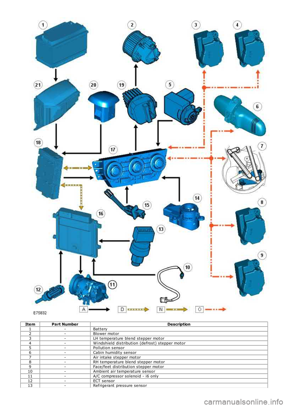
Ite mPart NumberDescription1-Bat tery2-Blower mot or3-LH tempera ture ble nd stepper mot or4-W i ndshield dis tribution (de fros t) s tepper motor5-Pol lution s ensor6-Cabin humidity sensor7-Air inta ke s tepper mot or8-RH temperature ble nd stepper mot or9-Face/fe et distribut ion s tepper mot or10-Ambient ai r tempe rature s ensor11-A/C compre ssor solenoid - i6 only12-ECT se nsor13-Ref rige rant pre ssure se nsor
Page 1652 of 3229
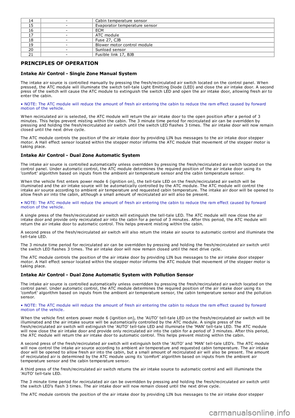
14-Cabin t empera ture sensor15-Eva porator temperature se nsor16-ECM17-ATC modul e18-Fus e 27, CJB19-Blower mot or control module20-Sunloa d se nsor21-Fus ible link 17, BJB
PRINCIPLES OF OPERATION
Intake Air Control - Single Zone Manual System
The i ntake a ir source is cont rolle d manually by press ing the fres h/re circulat ed a ir switch located on the control panel. W he npress ed, the ATC module wil l illuminate the swi tch t ell-tale Light Emitti ng Diode (LED) and clos e the a ir intake door. A secondpress of the swit ch will caus e the ATC module to extinguish the swi tch LED and ope n the a ir intake door, a llowing fres h ai r toe nte r the cabin.
• NO TE: The ATC module wil l reduce the amount of fres h ai r ent ering the ca bin to reduce the ra m e ffect ca used by forwardmoti on of the ve hicle .
W he n recirculate d ai r is sele cted, the ATC module will re turn the air int ake door to the ope n position a fter a pe riod of 3minutes. Thi s he lps prevent mis ting within t he cabin. The 3 minute time pe riod for reci rcula ted air can be overridde n bypress ing and hol ding the fre sh/re circulat ed a ir s witch until t he s witch LED fl ashes 3 times. The air inta ke door will now remainclose d until t he next drive cycle.
The ATC module controls the pos ition of the air inta ke door by providing LIN bus messa ges to t he a ir intake door s teppermotor. A Hal l eff ect sens or l ocat ed withi n the st epper motor inf orms the ATC module that move me nt of the ste ppe r motor ist aking pl ace.
Intake Air Control - Dual Zone Automatic System
The i ntake a ir source is cont rolle d automatically unl ess overridden by press ing the fresh/recirculate d ai r switch loca ted on thecontrol pane l. Under aut oma tic control, t he ATC module det ermi nes the require d position of the air inta ke door usi ng it s'comfort' algorithm based on inputs from the ambient ai r tempe rature s ensor and the ca bin temperature se nsor.
W he n the ve hicle firs t enters power mode 6 (ignition on), the te ll-ta le LED on t he fresh/recirculated air swi tch will bei lluminat ed a nd t he air intake source wil l be aut oma tica lly controlle d by the ATC modul e. The ATC module will cont rol t hei ntake ai r source accordi ng t o ambie nt a ir te mpe rature a nd requeste d ca bin temperature. The intake ai r door will be opene d toa llow fre sh a ir into t he cabin, alt hough a small a mount of re circulat ed a ir will a lso be prese nt.
• NO TE: The ATC module wil l reduce the amount of fres h ai r ent ering the ca bin to reduce the ra m e ffect ca used by forwardmoti on of the ve hicle .
A single pres s of the fres h/re circulat ed a ir s witch wi ll extinguish the tel l-tal e LED. The ATC module will now close t he a iri ntake door a nd provide only recircul ated air into the cabin f or a period of 3 minutes . Af ter this peri od, the ATC module wil lreturn the ai r int ake door to automa tic control. This helps preve nt misti ng withi n the ca bin.
A second pre ss of the fre sh/recircula ted air s wit ch will a lso return the intake air source to a utomati c control and ill uminate thet ell-t ale LED.
The 3 mi nute time period for recircul ated air can be ove rridden by press ing and holding the fres h/re circulate d a ir switch untilt he s witch LED fl ashes 3 times. The air inta ke door will now remain clos ed unti l the next drive cycle .
The ATC module controls the pos ition of the air inta ke door by providing LIN bus messa ges to t he a ir intake door s teppermotor. A Hal l eff ect sens or l ocat ed withi n the st epper motor inf orms the ATC module that move me nt of the ste ppe r motor ist aking pl ace.
Intake Air Control - Dual Zone Automatic System with Pollution Sensor
The i ntake a ir source is cont rolle d automatically unl ess overridden by press ing the fresh/recirculate d ai r switch loca ted on thecontrol pane l. Under aut oma tic control, t he ATC module det ermi nes the require d position of the air inta ke door usi ng it s'comfort' algorithm based on inputs from the ambient ai r tempe rature s ensor, t he cabin temperature se nsor and the pollut ions ens or.
• NO TE: The ATC module wil l reduce the amount of fres h ai r ent ering the ca bin to reduce the ra m e ffect ca used by forwardmoti on of the ve hicle .
W he n the ve hicle firs t enters power mode 6 (ignition on), the 'AUTO ' te ll-ta le LED on the fresh/reci rcul ated air swit ch will bei lluminat ed a nd t he air intake source wil l be aut oma tica lly controlle d by the ATC modul e. A single pres s of thef resh/recircul ated air swi tch will exti ngui sh t he 'AUTO' te ll-t ale LED and illumina te t he 'MAN' te ll-ta le LED. The ATC modulewill now clos e the ai r int ake door and provide only recirculat ed a ir into t he cabi n for a period of 3 minutes. Afte r this period,t he ATC module will return t he a ir intake door to automatic cont rol. This he lps prevent mist ing within t he cabin.
A second pre ss of the fre sh/recircula ted air s wit ch will e xtinguis h both t he 'AUTO' a nd 'MAN' tel l-ta le LED's . The ATC modulewill now cont rol the inta ke a ir source according t o a mbie nt a ir te mperat ure and request ed cabin tempe rature. The a ir intakedoor will be opened to a llow fres h a ir int o the ca bin, but a s mal l amount of reci rcul ated air will also be pre sent . The amountof re circulate d ai r is dete rmi ned by t he ATC module using it s 'comfort' a lgorithm based on i nputs from the ambient airt emperat ure sensor and the cabi n te mpe rature s ens or.
A thi rd press of t he f resh/recirculate d ai r switch returns the air i ntake s ource to aut oma tic cont rol a nd will illumina te the'AUTO' te ll-ta le LED.
The 3 mi nute time period for recircul ated air can be ove rridden by press ing and holding the fres h/re circulate d a ir switch untilt he s witch LED's flas h 3 time s. The air intake door will now remain clos ed until the next dri ve cycle .
The ATC module controls the pos ition of the air inta ke door by providing LIN bus messa ges to t he a ir intake door s tepper
Page 1653 of 3229
motor. A Hal l eff ect sens or l ocat ed withi n the st epper motor inf orms the ATC module that move me nt of the ste ppe r motor ist aking pl ace.
Air Temperature Control - Single Zone Manual System
Cabin tempe rature s election is made by turning the LH rota ry controller to t he required pos ition. Turning the controller counterclockwise wil l lower the tempera ture of t he air e xiting the heate r as sembly; turning the control ler clockwise wi ll rai se t het emperat ure of t he a ir exiting the he ate r as sembly.
Maxi mum he ating and cooling is represe nted on the control panel by a red a nd blue dot res pect ivel y. W hen eit her maximumheat ing or cooling is sele cte d, the 'comf ort' algorithm in the ATC modul e wi ll adopt a suitable s trat egy for air s ource, a irdistributi on a nd blower s pee d to ma inta in maximum hea ting or cool ing within t he cabin.
The ATC module adjusts the temperature of the air exit ing t he heat er a ssembly by moving the pos ition of the tempera tureblend door. The tempera ture ble nd door dire cts a proportion of cool ed a ir from t he evaporat or t hrough the heat er core toproduce the required temperature output. The ATC module a djusts t he posi tion of t he t empera ture blend door by provi dingLIN bus mes sage s to the ble nd door ste ppe r motor. A Hall e ffect se nsor located wit hin the stepper motor i nforms t he ATCmodule t hat moveme nt of the st epper motor is taking place .
Air Temperature Control - Dual Zone Automatic System
Dual zone systems f eature 2 rot ary heat ing cont rolle rs, which a llow indi vidual climate control for the LH and RH sides of thecabin. Te mpe rature s election can be ma de by turning the controller to t he requi red tempera ture ma rked on the control panel.Turni ng e ithe r controller pas t the 16°C (61°F) mark will initi ate the maximum cooling s trate gy; turning either controlle r pa stt he 28°C (82°F) mark wi ll initiat e the maximum hea ting stra tegy.
• NO TE: Maximum cooling or hea ting can only be achieved i f both rotary control lers are set to t he s ame position.
The ATC module is a ble to maint ain constant te mpe ratures in both side s of the cabin by monit oring the fee dba ck f rom thecabin temperature se nsor. Unles s any manual overri des have be en s ele cted, the ATC module will a utomati cally control thei ntake ai r source , air dis tribution int o the ca bin and blower spee d to ma inta in t he requi red tempera ture s.
Dual zone systems f eature 2 temperature bl end doors, a llowing individual t emperat ure output for t he LH a nd RH si des of t hecabin.
• NO TE: The drivers side temperature se tting ha s priorit y over t he pass engers s ide tempera ture se tting.
The t empera ture ble nd doors are mounte d on the LH side of the hea ter ass embly a nd direct a proportion of cooled air fromt he e vaporat or through t he heat er core t o provide the re quired t empera ture out puts . The ATC module controls the posi tion oft he t emperat ure blend doors by providing LIN bus mess ages to the blend door stepper mot ors. Hal l eff ect sens ors loca tedwithi n the st epper motors inform the ATC modul e that move ment of the ste ppe r motors is taki ng place .
Blower Motor Control - Single Zone Manual System
Blower motor spe ed is se t by turning the RH rot ary cont rolle r to the require d position. The RH rotary controller allows t hes election of 14 blowe r motor spe eds . Turning the controller fully counte r clockwise will turn the blower mot or off.
O peration of the blower mot or is control led by t he ATC module via t he blower motor control module . The ATC module provi desa PW M s igna l to the blower mot or control modul e ba sed on the sele cted blower spe ed. The blower mot or control modulei nterpret s the PW M s igna l as a blower motor spe ed and controls the vol tage to the blower mot or a ccordingly.
Blower Motor Control - Dual Zone Automatic System
Blower motor spe ed is controlled automa tica lly by the ATC module unle ss a ma nual override ha s be en requeste d. Manualoverrides to blower motor speed can be made by turning the centra l rot ary cont rolle r to the require d position. The rota rycontrolle r all ows the manual sele ction of 7 blower motor spe eds . Turning the controller fully counte r clockwise will turn theblower motor off . W hen a manua l override has been ma de, the 'AUTO' LED loca ted in the ce nte r of the rota ry controlle r wil le xtinguis h.
• NO TE: The central rota ry controller contains 2 LED's. The t op (round) LED will illumina te when the blower motor i s undera utomati c control. The bottom (recta ngular) LED wil l illuminated when a ir distri bution i nto the cabi n is under a utomati ccontrol (s ee below).
The blower motor ca n be ret urne d to aut oma tic cont rol by press ing the 'AUTO' s witch locate d in the center of t he rotarycontrolle r. Under aut oma tic cont rol, the ATC module varies t he s pee d of the blower motor i n line with i ts 'comf ort' algorithmt o maint ain t he required cabin te mperat ure. The ATC modul e wi ll al so vary the blower motor speed to compens ate for the rame ffect on inta ke air produced by forward moveme nt of the ve hicl e.
O peration of the blower mot or is control led by t he ATC module via t he blower motor control module . The ATC module provi desa PW M s igna l to the blower mot or control modul e ba sed on the required blower spe ed. The blower mot or control modulei nterpret s the PW M s igna l as a blower motor spe ed and controls the vol tage to the blower mot or a ccordingly.
Air Distribution Control - Single Zone Manual System
Air distri buti on into t he cabi n ca n be adj uste d by turning the ce ntra l rot ary cont rolle r to the require d positi on. The ATC modulea djus ts t he posit ion of t he a ir di stribution door to the re qui red posi tion by providing LIN bus messa ges to the air distribut iondoor stepper motor. A Ha ll e ffect se nsor loca ted wit hin the stepper mot or informs t he ATC module that movement of t hes tepper motor is taking place.
Air Distribution Control - Dual Zone Automatic System
Air distri buti on into t he cabi n is cont rolle d a utomati cally by the ATC module unless any ma nual ove rrides have bee nreque ste d. Manual overri des can be made by pre ssing the a ppropria te a ir di stribution mome nta ry s witch on the control panel.If a manual override has bee n re que sted, the 'AUTO ' LED locate d in the center of the blowe r motor rota ry controlle r wi lle xtinguis h.
• NO TE: The central rota ry controller contains 2 LED's. The t op (round) LED will illumina te when the blower motor i s undera utomati c control (se e a bove ). The bott om (rect angular) LED wi ll ill uminate d when air distribut ion into the cabin is under
Page 1654 of 3229
a utomati c control.
Air distri buti on can be re turned t o automatic control by pres sing the 'AUTO' swi tch loca ted in the ce nte r of the blower motorrotary controller. Thi s wi ll ill uminate the 'AUTO' LED and allow t he ATC module to control a ir di stribution in line wit h it s'comfort' algorithm
Air distri buti on is control led by 2 air dist ribution doors. The ATC module control s the position of the air dis tribution doors byprovi ding LIN bus me ssa ges to t he door ste pper motors . Ha ll ef fect sensors located wit hin the stepper mot ors inform t he ATCmodule t hat moveme nt of the st epper motors is taking place.
ECON - Single Zone Manual System
P ress ing the 'ECO N' moment ary swit ch on the control pa nel will swi tch off t he A/C s yste m. W he n s elected, the ATC modulewill t rans mit a mess age ove r the high speed CAN bus to the ECM re que sting the A/C compressor is dis able d. The ECMdisables the compres sor by de-e nergizing the A/C compress or control re lay loca ted in the BJB. The tell-tale LED in the swit chwill i lluminat e to ale rt the ve hicl e occupants tha t the system is in 'ECO N' mode .
W he n 'ECON' mode i s se lect ed, tempera ture control is s till a vai lable but no cooling of i ntake ai r wi ll ta ke place . The minimumoutput a ir te mpe rature f rom the sys tem will be ambient air tempera ture plus any heat pick up in the ai r int ake pat h.
A/C can be s witched back on by pres sing the 'ECON' swi tch a se cond time. This will als o extinguish the 'ECON' LED.
Stop/Sta rt Ve hicl es - From 2010 MY
From 2010 MY , t he 'ECON' switch wi ll be labeled ‘A/C’ to pre vent confus ion with the ‘Eco’ switch which operates the‘Stop/Sta rt’ a nd 'Gea r Change Indica tor' syst ems .For a ddit iona l inf ormation, re fer to: Starting Sys tem (303-06C Start ing Syst em - TD4 2.2L Diese l, Vehicles Buil t From:01-03-2009, Des cript ion and Ope rati on).
ECON - Dual Zone Automatic System
P ress ing the 'ECO N/O FF' momentary swi tch in the control pa nel will swi tch off t he A/C s yste m. W he n s elected, the ATCmodule will t rans mit a mess age ove r the high speed CAN bus to the ECM re que sting the A/C compress or is dis able d. The ECMdisables the compres sor by de-e nergizing the A/C compress or control re lay loca ted in the BJB. The 'ECO N' t ell-tale LED in t hes witch will il lumi nate to alert the ve hicle occupa nts that the sys tem is i n 'ECON' mode.
W he n 'ECON' mode i s se lect ed, tempera ture control is s till a vai lable but no cooling of i ntake ai r wi ll ta ke place . The minimumoutput a ir te mpe rature f rom the sys tem will be ambient air tempera ture plus any heat pick up in the ai r int ake pat h.
A second pre ss of the 'ECON/OFF' switch wil l ext inguish the 'ECO N' LED and illuminate the 'OFF' LED. W hen in 'OFF' mode t heATC module sets the blower mot or s pee d to 0. Air distri buti on i nto the cabi n wi ll remai n as pre viously sele cted. Al l LED's ont he control pane l wil l be ext inguishe d, a lthough night ti me illumina tion will remain acti ve.
• NO TE: W he n in 'OFF' mode , the he ated se at, heat ed windshie ld a nd heat ed rear window functions wi ll st ill be availa ble.
A thi rd press of t he 'ECO N/O FF' s wit ch re turns the s yste m to norma l (A/C) operation and extinguishes t he 'OFF' LED. Thes yste m can be re turned to a utomati c operat ion at a ny t ime by press ing the 'AUTO' swit ch mounted in t he cent ral (blowermotor) rotary control ler.
Stop/Sta rt Ve hicl es - From 2010 MY
From 2010 MY , t he 'ECON' switch wi ll be labeled ‘A/C’ to pre vent confus ion with the ‘Eco’ switch which operates the‘Stop/Sta rt’ a nd 'Gea r Change Indica tor' syst ems .For a ddit iona l inf ormation, re fer to: Starting Sys tem (303-06C Start ing Syst em - TD4 2.2L Diese l, Vehicles Buil t From:01-03-2009, Des cript ion and Ope rati on).
Programmed Defrost
The programmed def rost function is only ava ilable on ve hicl es fi tted wit h a dua l zone heati ng, vent ilat ion a nd A/C syst em.The f unction is s elected by press ing the 'PRO G' moment ary swit ch on the control pa nel. W hen s ele cted, the ATC moduleprovi des maximum winds hie ld de fros ting/de mist ing by confi guri ng t he s yste m a s follows:
'AUTO ' mode offIntake air set to fres h airAir di stribution se t to windshieldBlowe r motor spe ed s et t o maximumHeate d winds hiel d onRear window hea ter on.
W he n progra mmed defrost is sel ecte d, t he s et t emperat ure will remain unchanged. Programme d de fros t ca n be cancell ed bya ny of the following met hods:
P ress ing any air distribut ion moment ary swit chP ress ing the 'AUTO' s witch locate d in the center of t he blowe r motor rot ary cont rolle rP ress ing the 'PRO G' momenta ry s witch a second time .
• NO TE: Blower motor speed can be adjuste d wi thout te rmi nating programmed defrost.
Windshield Heater
The windshie ld heate r comprises 2 heate r el eme nts , LH and RH, bonded be twee n the glass laminat ions . The s yste m iss witched on by press ing the momentary swi tch l ocat ed on t he control panel . W hen selected, the ATC module t rans mits aheat ing request on t he high spe ed CAN bus to t he CJB. On rece ipt of the messa ge, the CJB ene rgiz es t he windshie ld heate rrelay loca ted in t he BJB by provi ding a ground path for t he relay coi l. The energized rela y provides a ba ttery fe ed t o bothheat er el eme nts . Aft er a period of 4 minutes the ATC module re moves t he request for windshie ld heati ng. The CJB the npowe rs down the windshield hea ter by re moving the ground pat h for the rel ay coil.
The ATC module will only reques t wi ndshield he ater ope rati on if the engine is runni ng. An e ngi ne s tatus si gnal is provi ded tot he ATC module by t he ECM over the high speed CAN bus.
Page 1656 of 3229
Publi s hed: 11-May-2011
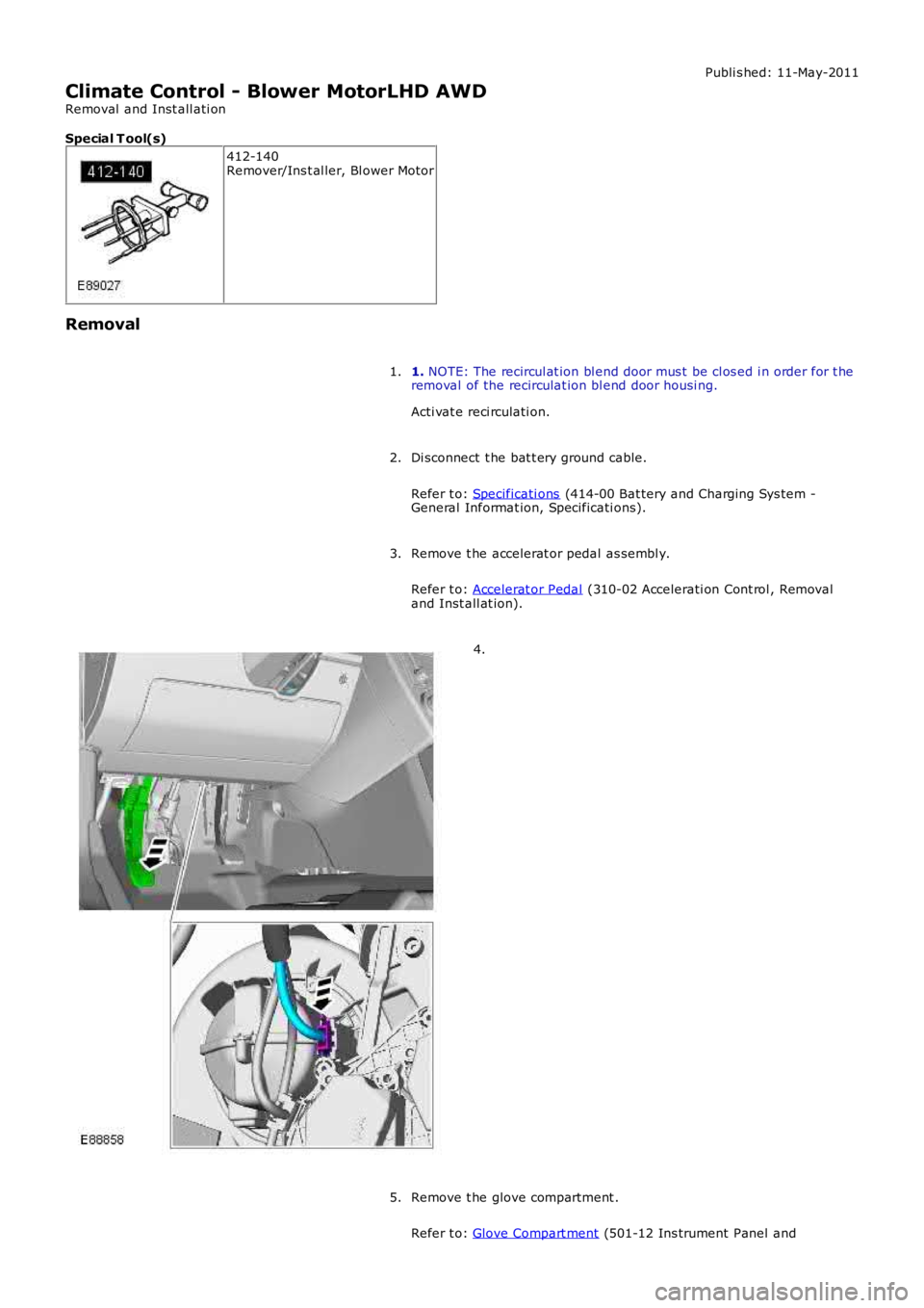
Climate Control - Blower MotorLHD AWD
Removal and Inst all ati on
Special T ool(s)
412-140Remover/Ins t al ler, Bl ower Motor
Removal
1. NOTE: The recircul at ion bl end door mus t be cl os ed i n order for t heremoval of the recirculat ion bl end door housi ng.
Acti vat e reci rculati on.
1.
Di sconnect t he bat t ery ground cable.
Refer t o: Specificati ons (414-00 Bat tery and Charging Sys tem -General Informat ion, Specificati ons).
2.
Remove t he accelerat or pedal as sembl y.
Refer t o: Accelerat or Pedal (310-02 Accelerati on Cont rol , Removaland Inst all at ion).
3.
4.
Remove t he glove compartment .
Refer t o: Glove Compart ment (501-12 Ins trument Panel and
5.
Page 1660 of 3229
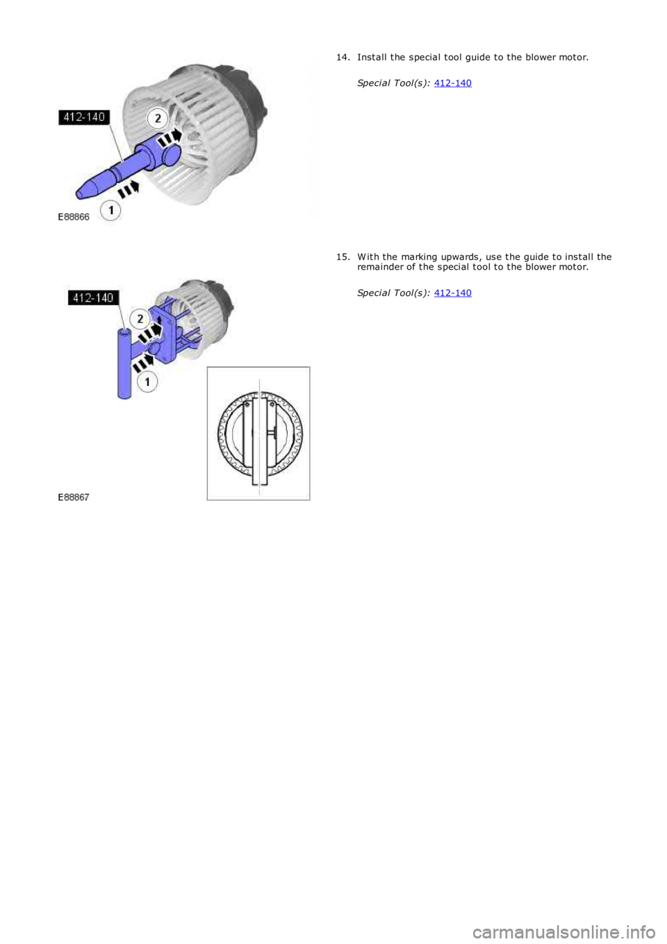
Inst all t he s pecial t ool guide t o t he blower mot or.
Speci al Tool (s ): 412-140 14.
W it h the marking upwards , us e t he guide t o ins t al l the
remainder of t he s peci al t ool t o t he blower mot or.
Speci al Tool (s ): 412-140 15.
Page 1661 of 3229
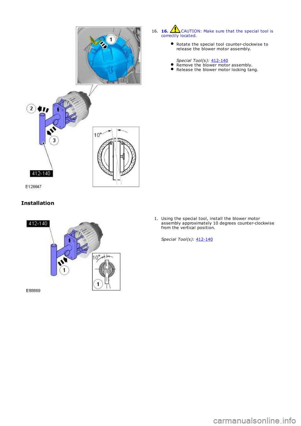
16. CAUTION: Make s ure t hat the special tool is
correct ly l ocat ed.
Rotat e t he s pecial t ool counter-clockwi s e t o
rel ease the bl ower mot or ass embl y.
Speci al Tool (s ): 412-140 Remove t he blower motor as s embly.
Releas e t he blower motor l ocking tang.16.
Installation Us ing t he s peci al t ool, i ns t all the bl ower motor
as sembl y approximat ely 10 degrees count er-clockwi s e
from the verti cal posi ti on.
Speci al Tool (s ): 412-140 1.