2006 DODGE RAM SRT-10 check engine
[x] Cancel search: check enginePage 2160 of 5267
TURBOCHARGER SYSTEM
DIAGNOSIS AND TESTING
TURBOCHARGER BOOST PRESSURE
Low turbocharger boost pressure can cause poor engine performance and driveability concerns. The following pro-
cedure will test the turbocharger boost pressure.
Causes of low boost pressure include the following:
Restricted air inlet system
Leak in charge air cooler system
Restricted/high pressure drop across charge air cooler
Damaged turbocharger compressor wheel housing
Turbocharger wastegate stuck open
Excessive exhaust restriction
Causes of excessively high boost pressure include:
Turbocharger wastegate stuck closed
Turbocharger wastegate signal line leaking or damaged
Damaged wastegate command valve O-rings
Wastegate command valve mechanically stuck in actuated position
Several Diagnostic Trouble Codes (DTCs) can be set that will indicate highor low system boost levels. There is a
DTC for circuit faults relating to the electronically controlled wastegate command valve.
(Refer to 11 - EXHAUST SYSTEM/TURBOCHARGER SYSTEM/CHARGE AIR COOLER AND PLUMBING - DIAG-
NOSIS AND TESTING) for diagnosing of low or high boost pressure due to leaks.
NOTE: If oil is present on either the inlet or exhaust side of the turbo charger, check the charge air cooler
for evidence of oil. Clean charge air cooler of any oil before starting the engine. Failure to do this can result
in severe engine damage.
Page 2165 of 5267
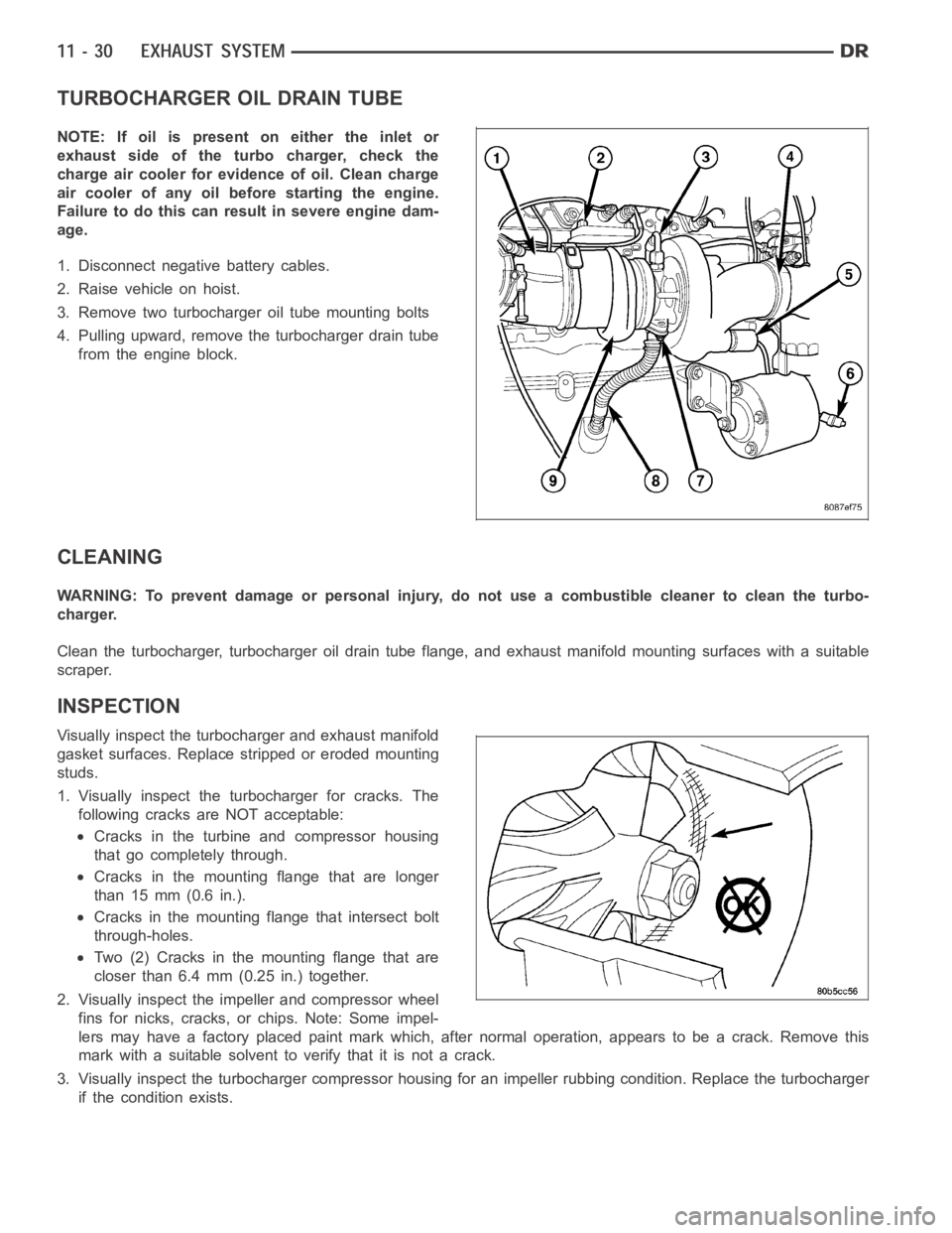
TURBOCHARGER OIL DRAIN TUBE
NOTE: If oil is present on either the inlet or
exhaust side of the turbo charger, check the
charge air cooler for evidence of oil. Clean charge
air cooler of any oil before starting the engine.
Failure to do this can result in severe engine dam-
age.
1. Disconnect negative battery cables.
2. Raise vehicle on hoist.
3. Remove two turbocharger oil tube mounting bolts
4. Pulling upward, remove the turbocharger drain tube
from the engine block.
CLEANING
WARNING: To prevent damage or personal injury, do not use a combustible cleaner to clean the turbo-
charger.
Clean the turbocharger, turbocharger oil drain tube flange, and exhaust manifold mounting surfaces with a suitable
scraper.
INSPECTION
Visually inspect the turbocharger and exhaust manifold
gasket surfaces. Replace stripped or eroded mounting
studs.
1. Visually inspect the turbocharger for cracks. The
following cracks are NOT acceptable:
Cracks in the turbine and compressor housing
that go completely through.
Cracks in the mounting flange that are longer
than 15 mm (0.6 in.).
Cracks in the mounting flange that intersect bolt
through-holes.
Two (2) Cracks in the mounting flange that are
closer than 6.4 mm (0.25 in.) together.
2. Visually inspect the impeller and compressor wheel
fins for nicks, cracks, or chips. Note: Some impel-
lers may have a factory placed paint mark which, after normal operation, appears to be a crack. Remove this
mark with a suitable solvent to verify that it is not a crack.
3. Visually inspect the turbocharger compressor housing for an impeller rubbing condition. Replace the turbocharger
if the condition exists.
Page 2167 of 5267
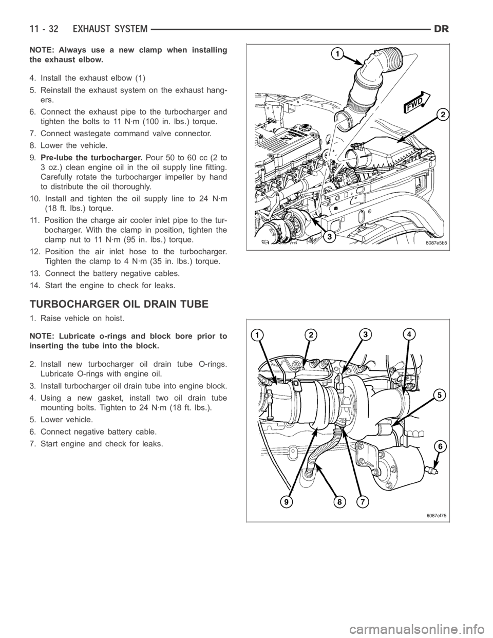
NOTE: Always use a new clamp when installing
the exhaust elbow.
4. Install the exhaust elbow (1)
5. Reinstall the exhaust system on the exhaust hang-
ers.
6. Connect the exhaust pipe to the turbocharger and
tighten the bolts to 11 Nꞏm (100 in. lbs.) torque.
7. Connect wastegate command valve connector.
8. Lower the vehicle.
9.Pre-lube the turbocharger.Pour 50 to 60 cc (2 to
3 oz.) clean engine oil in the oil supply line fitting.
Carefully rotate the turbocharger impeller by hand
to distribute the oil thoroughly.
10. Install and tighten the oil supply line to 24 Nꞏm
(18 ft. lbs.) torque.
11. Position the charge air cooler inlet pipe to the tur-
bocharger. With the clamp in position, tighten the
clamp nut to 11 Nꞏm (95 in. lbs.) torque.
12. Position the air inlet hose to the turbocharger.
Tighten the clamp to 4 Nꞏm (35 in. lbs.) torque.
13. Connect the battery negative cables.
14. Start the engine to check for leaks.
TURBOCHARGER OIL DRAIN TUBE
1. Raise vehicle on hoist.
NOTE: Lubricate o-rings and block bore prior to
inserting the tube into the block.
2. Install new turbocharger oil drain tube O-rings.
Lubricate O-rings with engine oil.
3. Install turbocharger oil drain tube into engine block.
4. Using a new gasket, install two oil drain tube
mounting bolts. Tighten to 24 Nꞏm (18 ft. lbs.).
5. Lower vehicle.
6. Connect negative battery cable.
7. Start engine and check for leaks.
Page 2170 of 5267
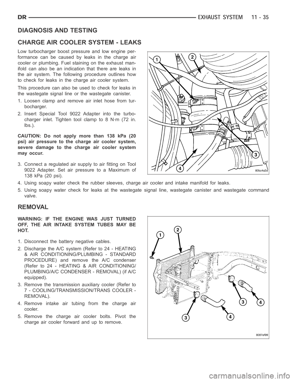
DIAGNOSIS AND TESTING
CHARGE AIR COOLER SYSTEM - LEAKS
Low turbocharger boost pressure and low engine per-
formance can be caused by leaks in the charge air
cooler or plumbing. Fuel staining on the exhaust man-
ifold can also be an indication that there are leaks in
the air system. The followingprocedure outlines how
to check for leaks in the charge air cooler system.
This procedure can also be used to check for leaks in
the wastegate signal line or the wastegate canister.
1. Loosen clamp and remove air inlet hose from tur-
bocharger.
2. Insert Special Tool 9022 Adapter into the turbo-
charger inlet. Tighten tool clamp to 8 Nꞏm (72 in.
lbs.).
CAUTION: Do not apply more than 138 kPa (20
psi) air pressure to the charge air cooler system,
severe damage to the charge air cooler system
may occur.
3. Connect a regulated air supply to air fitting on Tool
9022 Adapter. Set air pressure to a Maximum of
138 kPa (20 psi).
4. Using soapy water check the rubber sleeves, charge air cooler and intakemanifold for leaks.
5. Using soapy water check for leaks at the wastegate signal line, wastegate canister and wastegate command
valve.
REMOVAL
WARNING: IF THE ENGINE WAS JUST TURNED
OFF, THE AIR INTAKE SYSTEM TUBES MAY BE
HOT.
1. Disconnect the battery negative cables.
2. Discharge the A/C system (Refer to 24 - HEATING
& AIR CONDITIONING/PLUMBING - STANDARD
PROCEDURE) and remove the A/C condenser
(Refer to 24 - HEATING & AIR CONDITIONING/
PLUMBING/A/C CONDENSER - REMOVAL) (if A/C
equipped).
3. Remove the transmission auxiliary cooler (Refer to
7 - COOLING/TRANSMISSION/TRANS COOLER -
REMOVAL).
4. Remove intake air tubing from the charge air
cooler.
5. Remove the charge air cooler bolts. Pivot the
charge air cooler forward and up to remove.
Page 2172 of 5267
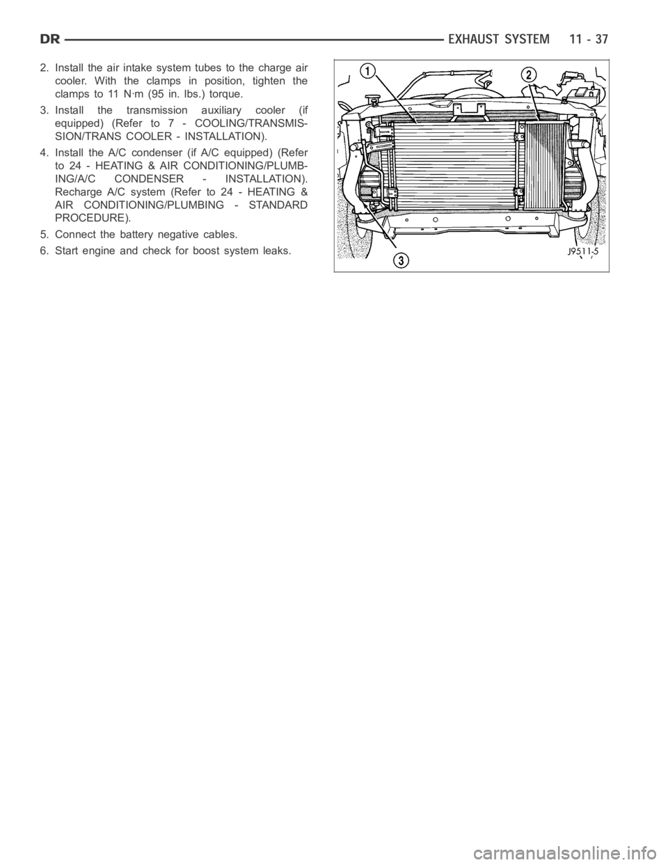
2. Install the air intake system tubes to the charge air
cooler. With the clamps in position, tighten the
clamps to 11 Nꞏm (95 in. lbs.) torque.
3. Install the transmission auxiliary cooler (if
equipped) (Refer to 7 - COOLING/TRANSMIS-
SION/TRANS COOLER - INSTALLATION).
4. Install the A/C condenser (if A/C equipped) (Refer
to 24 - HEATING & AIR CONDITIONING/PLUMB-
ING/A/C CONDENSER - INSTALLATION).
Recharge A/C system (Refer to 24 - HEATING &
AIR CONDITIONING/PLUMBING - STANDARD
PROCEDURE).
5. Connect the battery negative cables.
6. Start engine and check for boost system leaks.
Page 2241 of 5267
OPERATION
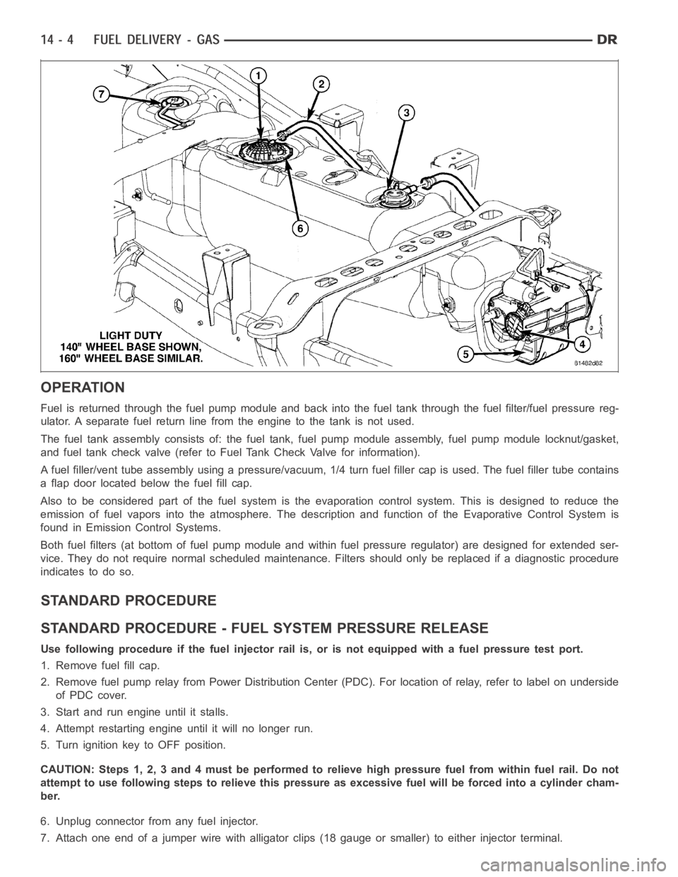
Fuel is returned through the fuel pump module and back into the fuel tank through the fuel filter/fuel pressure reg-
ulator. A separate fuel return line from the engine to the tank is not used.
The fuel tank assembly consists of: the fuel tank, fuel pump module assembly, fuel pump module locknut/gasket,
and fuel tank check valve (refer to Fuel Tank Check Valve for information).
A fuel filler/vent tube assembly using apressure/vacuum,1/4 turn fuel filler cap is used. The fuel filler tube contains
a flap door located below the fuel fill cap.
Also to be considered part of the fuelsystem is the evaporation control system. This is designed to reduce the
emission of fuel vapors into the atmosphere. The description and functionof the Evaporative Control System is
found in Emission Control Systems.
Both fuel filters (at bottom of fuel pump module and within fuel pressure regulator) are designed for extended ser-
vice. They do not require normal scheduled maintenance. Filters should only be replaced if a diagnostic procedure
indicates to do so.
STANDARD PROCEDURE
STANDARD PROCEDURE - FUEL SYSTEM PRESSURE RELEASE
Use following procedure if the fuel injector rail is, or is not equipped with a fuel pressure test port.
1. Remove fuel fill cap.
2. Remove fuel pump relay from Power Distribution Center (PDC). For location of relay, refer to label on underside
of PDC cover.
3. Start and run engine until it stalls.
4. Attempt restarting engine until it will no longer run.
5. Turn ignition key to OFF position.
CAUTION: Steps 1, 2, 3 and 4 must be performed to relieve high pressure fuel from within fuel rail. Do not
attempt to use following steps to relieve this pressure as excessive fuel will be forced into a cylinder cham-
ber.
6. Unplug connector from any fuel injector.
7. Attach one end of a jumper wire with alligator clips (18 gauge or smaller)to either injector terminal.
Page 2242 of 5267

8. Connect other end of jumper wire to positive side of battery.
9. Connect one end of a second jumper wire to remaining injector terminal.
CAUTION: Powering an injector for more than a few seconds will permanentlydamage the injector.
10. Momentarily touch other end of jumper wire to negative terminal of battery for no more than a few seconds.
11. Place a rag or towel below fuel line quick-connect fitting at fuel rail.
12. Disconnect quick-connect fitting at fuel rail. Refer to Quick-Connect Fittings.
13. Return fuel pump relay to PDC.
14. One or more Diagnostic Trouble Codes (DTC’s) may have been stored in PCMmemory due to fuel pump relay
removal. The DRB
scantoolmustbeusedtoeraseaDTC.
STANDARD PROCEDURE - DRAINING FUEL TANK - EXCEPT DIESEL
WARNING: The fuel system may be under constant fuel pressure even with the engine off. This pressure
must be released before servicing fuel tank.
Two different procedures may be used to drain fuel tank: through the fuel fill fitting on tank, or using a diagnostic
scan tool to activate the fuel pump relay. Due to a one-way check valve installed into the fuel fill opening fitting at
the tank, the tank cannot be drained conventionally at the fill cap.
The quickest draining procedure involves removing the rubber fuel fill hose at the fuel tank.
As an alternative procedure, the electric fuel pump may be activated allowingtanktobedrainedatfuelrailcon-
nection. Refer to diagnostic scan tool for fuel pump activation procedures. Before disconnecting fuel line at fuel rail,
release fuel pressure. Refer to the Fuel System Pressure Release Procedure for procedures. Attach end of special
test hose tool number 6631 or 6539 at fuel rail disconnection (tool number 6631isusedon5/16”fuellineswhile
tool number 6539 is used on 3/8” fuel lines). Position opposite end of this hose tool to an approved gasoline drain-
ing station. Activate fuel pump and drain tank until empty.
If electric fuel pump is not operating, fuel must be drained through fuel fill fitting at tank. Refer to following proce-
dures.
1. Release fuel system pressure.
2. Raise vehicle.
3. Thoroughly clean area around fuel fill fitting and rubber fuel fill hoseat tank.
4. If vehicle is equipped with 4 doors and a 6 foot (short) box, remove left-rear tire/wheel.
5. Loosen clamp and disconnect rubber fuel fill hose at tank fitting. Usingan approved gas holding tank, drain fuel
tank through this fitting.
SPECIFICATIONS
FUEL SYSTEM PRESSURE
58 psi +/- 2 psi
TORQUE - EXCEPT DIESEL
DESCRIPTION N-m Ft. Lbs. In. Lbs.
Accelerator Pedal Bracket
Mounting12 - 105
Accelerator Pedal Position
Sensor Bracket-to-Battery
Tray Bolts3-30
Crankshaft Position
Sensor - 3.7L28 21 -
Crankshaft Position
Sensor - 4.7L28 21 -
Page 2246 of 5267
FUEL FILTER/PRESSURE REGULATOR
DESCRIPTION
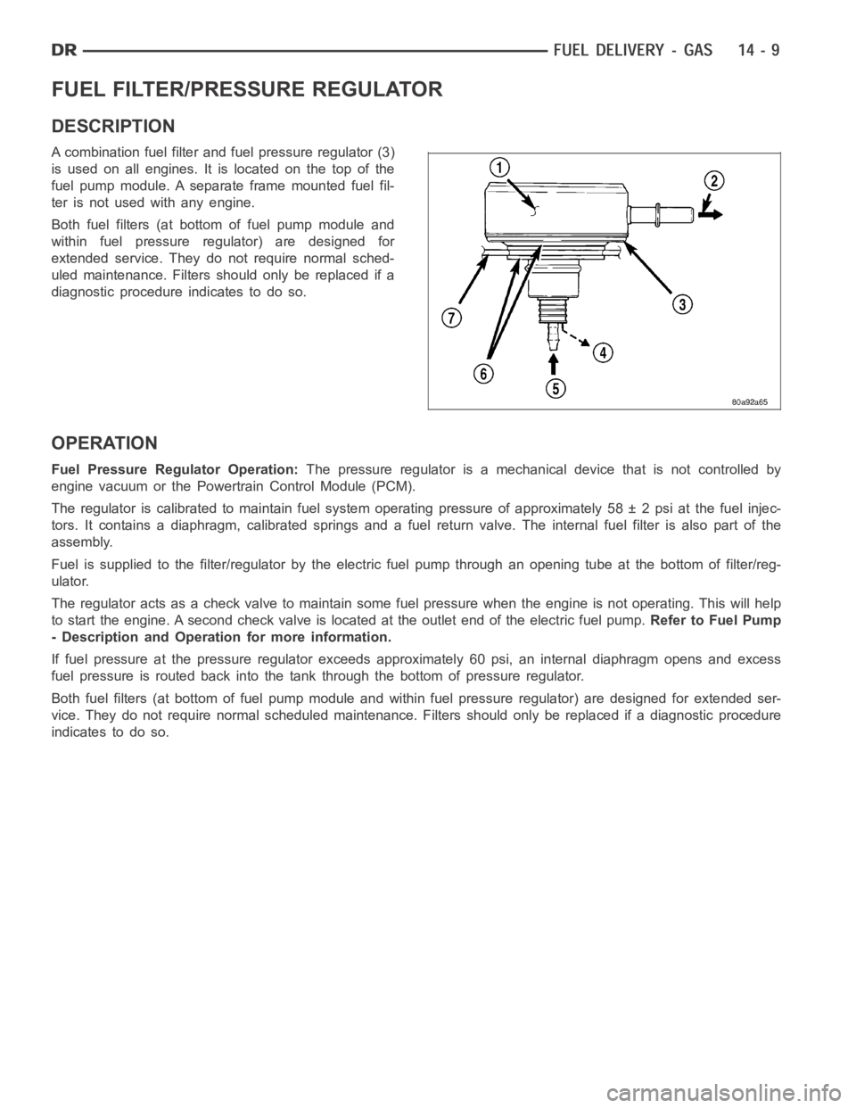
A combination fuel filter and fuel pressure regulator (3)
is used on all engines. It is located on the top of the
fuel pump module. A separate frame mounted fuel fil-
ter is not used with any engine.
Both fuel filters (at bottom of fuel pump module and
within fuel pressure regulator) are designed for
extended service. They do not require normal sched-
uled maintenance. Filters should only be replaced if a
diagnostic procedure indicates to do so.
OPERATION
Fuel Pressure Regulator Operation:The pressure regulator is a mechanical device that is not controlled by
engine vacuum or the Powertrain Control Module (PCM).
The regulator is calibrated to maintain fuel system operating pressure ofapproximately 58 ± 2 psi at the fuel injec-
tors. It contains a diaphragm, calibrated springs and a fuel return valve.The internal fuel filter is also part of the
assembly.
Fuel is supplied to the filter/regulator by the electric fuel pump throughan opening tube at the bottom of filter/reg-
ulator.
The regulator acts as a check valve to maintain some fuel pressure when the engine is not operating. This will help
to start the engine. A second check valve is located at the outlet end of the electric fuel pump.Refer to Fuel Pump
- Description and Operation for more information.
If fuel pressure at the pressure regulator exceeds approximately 60 psi, an internal diaphragm opens and excess
fuel pressure is routed back into the tank through the bottom of pressure regulator.
Both fuel filters (at bottom of fuel pump module and within fuel pressure regulator) are designed for extended ser-
vice. They do not require normal scheduled maintenance. Filters should only be replaced if a diagnostic procedure
indicates to do so.