2006 DODGE RAM SRT-10 check engine
[x] Cancel search: check enginePage 2027 of 5267
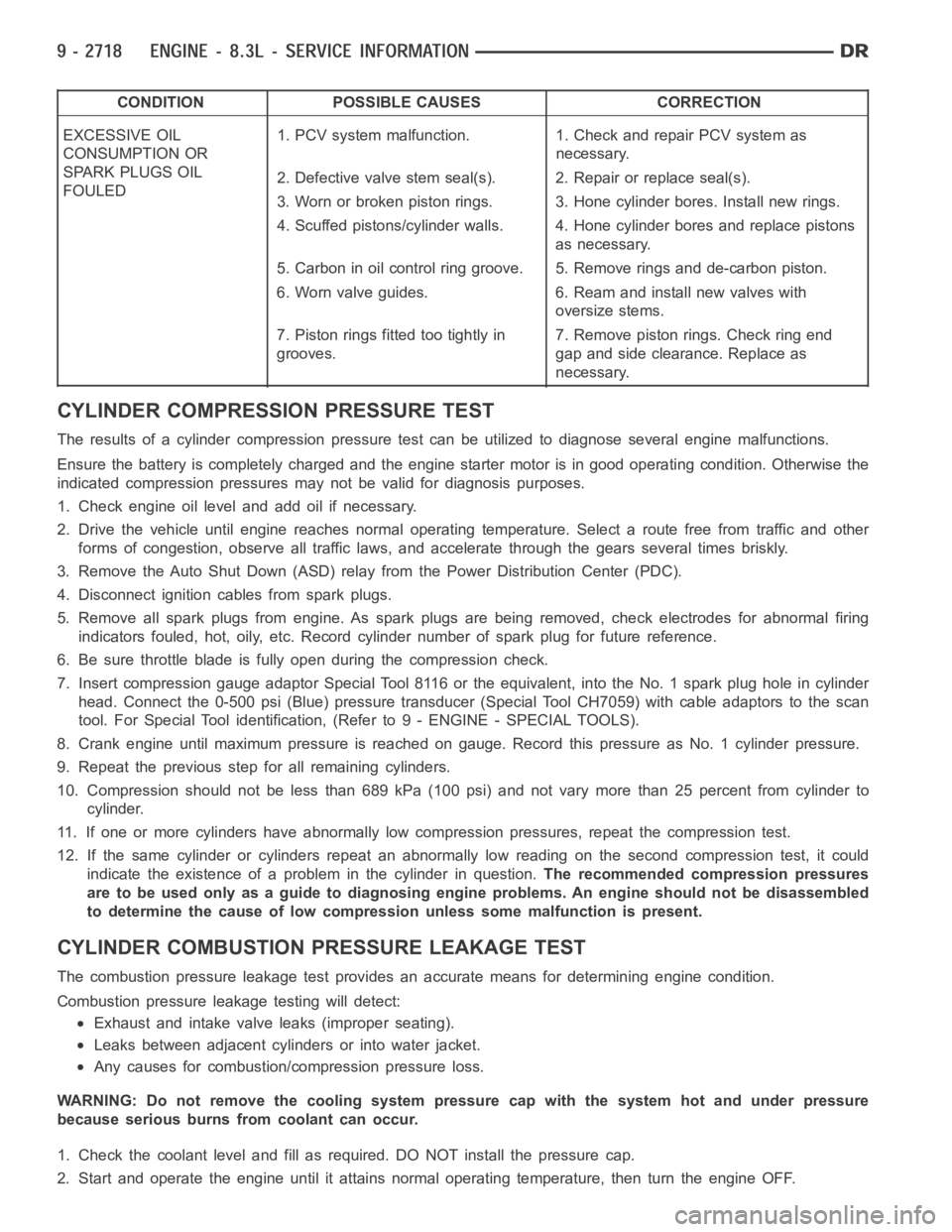
CONDITION POSSIBLE CAUSES CORRECTION
EXCESSIVE OIL
CONSUMPTION OR
SPARK PLUGS OIL
FOULED1. PCV system malfunction. 1. Check and repair PCV system as
necessary.
2. Defective valve stem seal(s). 2. Repair or replace seal(s).
3. Worn or broken piston rings. 3. Hone cylinder bores. Install new rings.
4. Scuffed pistons/cylinder walls. 4. Hone cylinder bores and replace pistons
as necessary.
5. Carbon in oil control ring groove. 5. Remove rings and de-carbon piston.
6. Worn valve guides. 6. Ream and install new valves with
oversize stems.
7. Piston rings fitted too tightly in
grooves.7. Remove piston rings. Check ring end
gap and side clearance. Replace as
necessary.
CYLINDER COMPRESSION PRESSURE TEST
The results of a cylinder compressionpressure test can be utilized to diagnose several engine malfunctions.
Ensurethebatteryiscompletelychargedandtheenginestartermotorisingood operating condition. Otherwise the
indicated compression pressures may not be valid for diagnosis purposes.
1. Check engine oil level and add oil if necessary.
2. Drive the vehicle until engine reaches normal operating temperature. Select a route free from traffic and other
forms of congestion, observe all traffic laws, and accelerate through thegears several times briskly.
3. Remove the Auto Shut Down (ASD) relay from the Power Distribution Center(PDC).
4. Disconnect ignition cables from spark plugs.
5. Remove all spark plugs from engine. As spark plugs are being removed, check electrodes for abnormal firing
indicators fouled, hot, oily, etc. Record cylinder number of spark plug for future reference.
6. Be sure throttle blade is fully open during the compression check.
7. Insert compression gauge adaptor Special Tool 8116 or the equivalent, into the No. 1 spark plug hole in cylinder
head. Connect the 0-500 psi (Blue) pressure transducer (Special Tool CH7059) with cable adaptors to the scan
tool. For Special Tool identification, (Refer to 9 - ENGINE - SPECIAL TOOLS).
8. Crank engine until maximum pressure is reached on gauge. Record this pressure as No. 1 cylinder pressure.
9. Repeat the previous step for all remaining cylinders.
10. Compression should not be less than 689 kPa (100 psi) and not vary more than 25 percent from cylinder to
cylinder.
11. If one or more cylinders have abnormally low compression pressures, repeat the compression test.
12. If the same cylinder or cylinders repeat an abnormally low reading on the second compression test, it could
indicate the existence of a problem in the cylinder in question.The recommended compression pressures
are to be used only as a guide to diagnosing engine problems. An engine should not be disassembled
to determine the cause of low compression unless some malfunction is present.
CYLINDER COMBUSTIONPRESSURE LEAKAGE TEST
The combustion pressure leakage test provides an accurate means for determining engine condition.
Combustion pressure leakage testing will detect:
Exhaust and intake valve leaks (improper seating).
Leaks between adjacent cylinders or into water jacket.
Any causes for combustion/compression pressure loss.
WARNING: Do not remove the cooling system pressure cap with the system hot and under pressure
because serious burns from coolant can occur.
1. Check the coolant level and fill as required. DO NOT install the pressurecap.
2. Start and operate the engine until it attains normal operating temperature, then turn the engine OFF.
Page 2028 of 5267
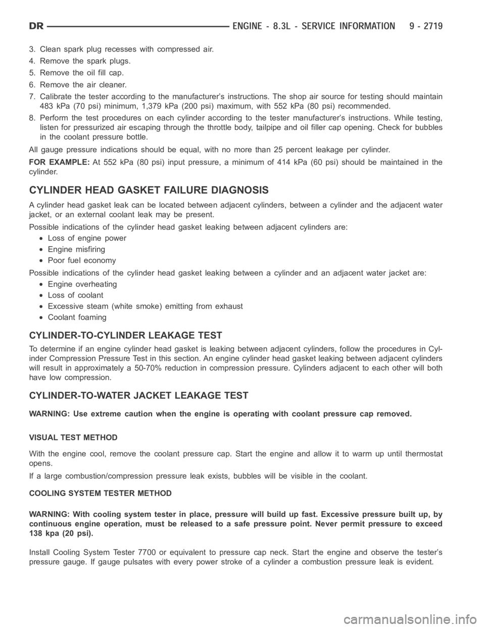
3. Clean spark plug recesses with compressed air.
4. Remove the spark plugs.
5. Remove the oil fill cap.
6. Remove the air cleaner.
7. Calibrate the tester according to the manufacturer’s instructions. The shop air source for testing should maintain
483 kPa (70 psi) minimum, 1,379 kPa (200 psi) maximum, with 552 kPa (80 psi) recommended.
8. Perform the test procedures on each cylinder according to the tester manufacturer’s instructions. While testing,
listen for pressurized air escaping through the throttle body, tailpipe and oil filler cap opening. Check for bubbles
in the coolant pressure bottle.
All gauge pressure indications should be equal, with no more than 25 percent leakage per cylinder.
FOR EXAMPLE:At 552 kPa (80 psi) input pressure, a minimum of 414 kPa (60 psi) should be maintained in the
cylinder.
CYLINDER HEAD GASKET FAILURE DIAGNOSIS
A cylinder head gasket leak can be located between adjacent cylinders, between a cylinder and the adjacent water
jacket, or an external coolant leak may be present.
Possible indications of the cylinder head gasket leaking between adjacent cylinders are:
Loss of engine power
Engine misfiring
Poor fuel economy
Possible indications of the cylinder head gasket leaking between a cylinder and an adjacent water jacket are:
Engine overheating
Loss of coolant
Excessive steam (white smoke) emitting from exhaust
Coolant foaming
CYLINDER-TO-CYLINDER LEAKAGE TEST
To determine if an engine cylinder head gasket is leaking between adjacentcylinders, follow the procedures in Cyl-
inder Compression Pressure Test in this section. An engine cylinder head gasket leaking between adjacent cylinders
will result in approximately a 50-70% reduction in compression pressure.Cylinders adjacent to each other will both
have low compression.
CYLINDER-TO-WATER JACKET LEAKAGE TEST
WARNING: Use extreme caution when the engine is operating with coolant pressure cap removed.
VISUAL TEST METHOD
With the engine cool, remove the coolant pressure cap. Start the engine andallow it to warm up until thermostat
opens.
If a large combustion/compression pressure leak exists, bubbles will be visible in the coolant.
COOLING SYSTEM TESTER METHOD
WARNING: With cooling system tester in place, pressure will build up fast.Excessive pressure built up, by
continuous engine operation, must be released to a safe pressure point. Never permit pressure to exceed
138 kpa (20 psi).
Install Cooling System Tester 7700 or equivalent to pressure cap neck. Start the engine and observe the tester’s
pressure gauge. If gauge pulsates with every power stroke of a cylinder a combustion pressure leak is evident.
Page 2029 of 5267
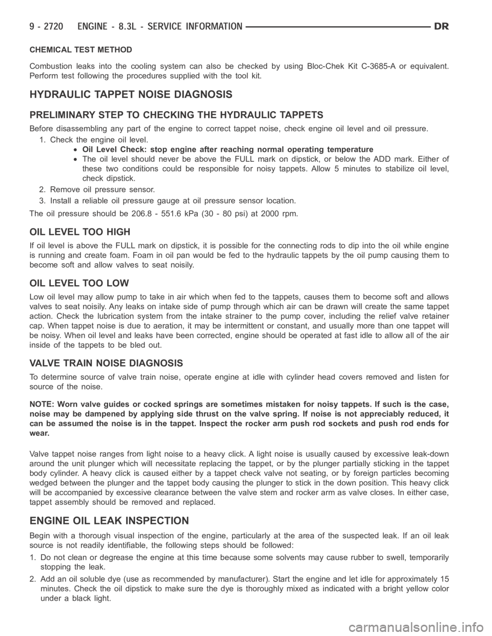
CHEMICAL TEST METHOD
Combustion leaks into the cooling system can also be checked by using Bloc-Chek Kit C-3685-A or equivalent.
Perform test following the procedures supplied with the tool kit.
HYDRAULIC TAPPET NOISE DIAGNOSIS
PRELIMINARY STEP TO CHECKING THE HYDRAULIC TAPPETS
Before disassembling any part of the engine to correct tappet noise, checkengine oil level and oil pressure.
1. Check the engine oil level.
Oil Level Check: stop engine after reaching normal operating temperature
The oil level should never be above the FULL mark on dipstick, or below the ADD mark. Either of
these two conditions could be responsible for noisy tappets. Allow 5 minutes to stabilize oil level,
check dipstick.
2. Remove oil pressure sensor.
3. Install a reliable oil pressure gauge at oil pressure sensor location.
The oil pressure should be 206.8 - 551.6 kPa (30 - 80 psi) at 2000 rpm.
OIL LEVEL TOO HIGH
If oil level is above the FULL mark on dipstick, it is possible for the connecting rods to dip into the oil while engine
is running and create foam. Foam in oil pan would be fed to the hydraulic tappets by the oil pump causing them to
become soft and allow valves to seat noisily.
OIL LEVEL TOO LOW
Low oil level may allow pump to take in air which when fed to the tappets, causes them to become soft and allows
valves to seat noisily. Any leaks on intake side of pump through which air canbedrawnwillcreatethesametappet
action. Check the lubrication system from the intake strainer to the pump cover, including the relief valve retainer
cap. When tappet noise is due to aeration, it may be intermittent or constant, and usually more than one tappet will
be noisy. When oil level and leaks have been corrected, engine should be operated at fast idle to allow all of the air
inside of the tappets to be bled out.
VALVE TRAIN NOISE DIAGNOSIS
To determine source of valve train noise, operate engine at idle with cylinder head covers removed and listen for
source of the noise.
NOTE: Worn valve guides or cocked springs are sometimes mistaken for noisytappets. If such is the case,
noise may be dampened by applying side thrust on the valve spring. If noise is not appreciably reduced, it
can be assumed the noise is in the tappet. Inspect the rocker arm push rod sockets and push rod ends for
wear.
Valve tappet noise ranges from light noise to a heavy click. A light noise isusually caused by excessive leak-down
around the unit plunger which will necessitate replacing the tappet, or bythe plunger partially sticking in the tappet
body cylinder. A heavy click is caused either by a tappet check valve not seating, or by foreign particles becoming
wedged between the plunger and the tappet body causing the plunger to stickin the down position. This heavy click
will be accompanied by excessive clearance between the valve stem and rocker arm as valve closes. In either case,
tappet assembly should be removed and replaced.
ENGINE OIL LEAK INSPECTION
Begin with a thorough visual inspection of the engine, particularly at thearea of the suspected leak. If an oil leak
source is not readily identifiable, thefollowingstepsshouldbefollowed:
1. Do not clean or degrease the engine at this time because some solvents maycause rubber to swell, temporarily
stopping the leak.
2. Add an oil soluble dye (use as recommended by manufacturer). Start the engine and let idle for approximately 15
minutes. Check the oil dipstick to make sure the dye is thoroughly mixed as indicated with a bright yellow color
under a black light.
Page 2030 of 5267
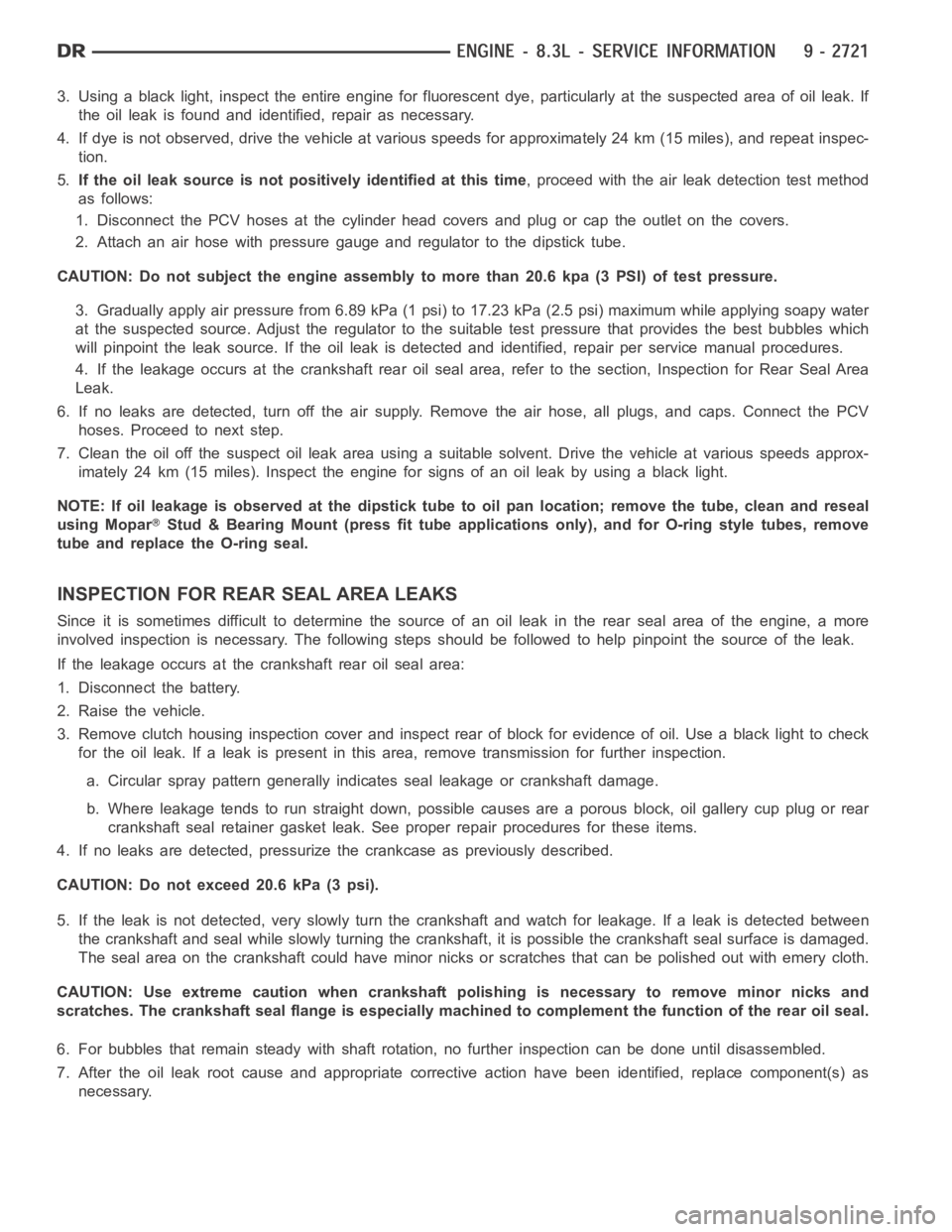
3. Using a black light, inspect the entire engine for fluorescent dye, particularly at the suspected area of oil leak. If
the oil leak is found and identified, repair as necessary.
4. If dye is not observed, drive the vehicle at various speeds for approximately 24 km (15 miles), and repeat inspec-
tion.
5.If the oil leak source is not positively identified at this time, proceed with the air leak detection test method
as follows:
1. Disconnect the PCV hoses at the cylinder head covers and plug or cap the outlet on the covers.
2. Attach an air hose with pressure gauge and regulator to the dipstick tube.
CAUTION: Do not subject the engine assembly to more than 20.6 kpa (3 PSI) of test pressure.
3. Gradually apply air pressure from 6.89 kPa (1 psi) to 17.23 kPa (2.5 psi) maximum while applying soapy water
at the suspected source. Adjust the regulator to the suitable test pressure that provides the best bubbles which
will pinpoint the leak source. If the oil leak is detected and identified, repair per service manual procedures.
4. If the leakage occurs at the crankshaft rear oil seal area, refer to the section, Inspection for Rear Seal Area
Leak.
6. If no leaks are detected, turn off the air supply. Remove the air hose, allplugs, and caps. Connect the PCV
hoses. Proceed to next step.
7. Clean the oil off the suspect oil leak area using a suitable solvent. Drive the vehicle at various speeds approx-
imately 24 km (15 miles). Inspect the engine for signs of an oil leak by usinga black light.
NOTE: If oil leakage is observed at the dipstick tube to oil pan location; remove the tube, clean and reseal
using Mopar
Stud & Bearing Mount (press fit tube applications only), and for O-ring style tubes, remove
tube and replace the O-ring seal.
INSPECTION FOR REAR SEAL AREA LEAKS
Since it is sometimes difficult to determine the source of an oil leak in therear seal area of the engine, a more
involved inspection is necessary. The following steps should be followedto help pinpoint the source of the leak.
If the leakage occurs at the crankshaft rear oil seal area:
1. Disconnect the battery.
2. Raise the vehicle.
3. Remove clutch housing inspection cover and inspect rear of block for evidence of oil. Use a black light to check
for the oil leak. If a leak is present in this area, remove transmission for further inspection.
a. Circular spray pattern generally indicates seal leakage or crankshaftdamage.
b. Where leakage tends to run straight down, possible causes are a porous block, oil gallery cup plug or rear
crankshaft seal retainer gasket leak. See proper repair procedures for these items.
4. If no leaks are detected, pressurize the crankcase as previously described.
CAUTION: Do not exceed 20.6 kPa (3 psi).
5. If the leak is not detected, very slowly turn the crankshaft and watch forleakage. If a leak is detected between
the crankshaft and seal while slowly turning the crankshaft, it is possible the crankshaft seal surface is damaged.
The seal area on the crankshaft could have minor nicks or scratches that canbe polished out with emery cloth.
CAUTION: Use extreme caution when crankshaft polishing is necessary to remove minor nicks and
scratches. The crankshaft seal flange is especially machined to complement the function of the rear oil seal.
6. For bubbles that remain steady with shaft rotation, no further inspection can be done until disassembled.
7. After the oil leak root cause and appropriate corrective action have been identified, replace component(s) as
necessary.
Page 2033 of 5267
5. Identify the fluid in the cylinder(s) (i.e., coolant, fuel, oil or other).
6. Make sure all fluid has been removed from the cylinders. Inspect engine for damage (i.e., connecting rods, pis-
tons, valves, etc.)
7. Repair engine or components as necessary to prevent this problem from re-occurring.
CAUTION: Squirt approximately one teaspoon of oil into the cylinders, rotateenginetolubricatethecylin-
der walls to prevent damage on restart.
8. Install new spark plugs.
9. Drain engine oil and remove oil filter.
10. Fill engine with specified amount of approved oil and install new oil filter.
11. Connect negative battery cable.
12. Start engine and check for any leaks.
REMOVAL - ENGINE ASSEMBLY
1. Perform fuel pressure release procedure (Refer to
14 - FUEL SYSTEM/FUEL DELIVERY - STAN-
DARD PROCEDURE).
2. Disconnect negative battery cable.
3. Disconnect throttle body air inlet duct, remove air
cleaner cover (Refer to 9 - ENGINE/AIR INTAKE
SYSTEM/AIR CLEANER ELEMENT - REMOVAL).
4. Raise and support the vehicle.
5. Remove the lower engine shield.
6. Drain cooling system (Refer to 7 - COOLING/EN-
GINE - STANDARD PROCEDURE - DRAINING
COOLING SYSTEM).
7. Paint mark and remove the driveshaft (Refer to 3 -
DIFFERENTIAL & DRIVELINE/PROPELLER
SHAFT/PROPELLER SHAFT - REMOVAL).
8.Removethetransmission(Referto21-TRANS-
MISSION/TRANSAXLE/MANUAL - REMOVAL).
9. Remove the starter (Refer to 8 - ELECTRICAL/
STARTING/STARTER MOTOR - REMOVAL).
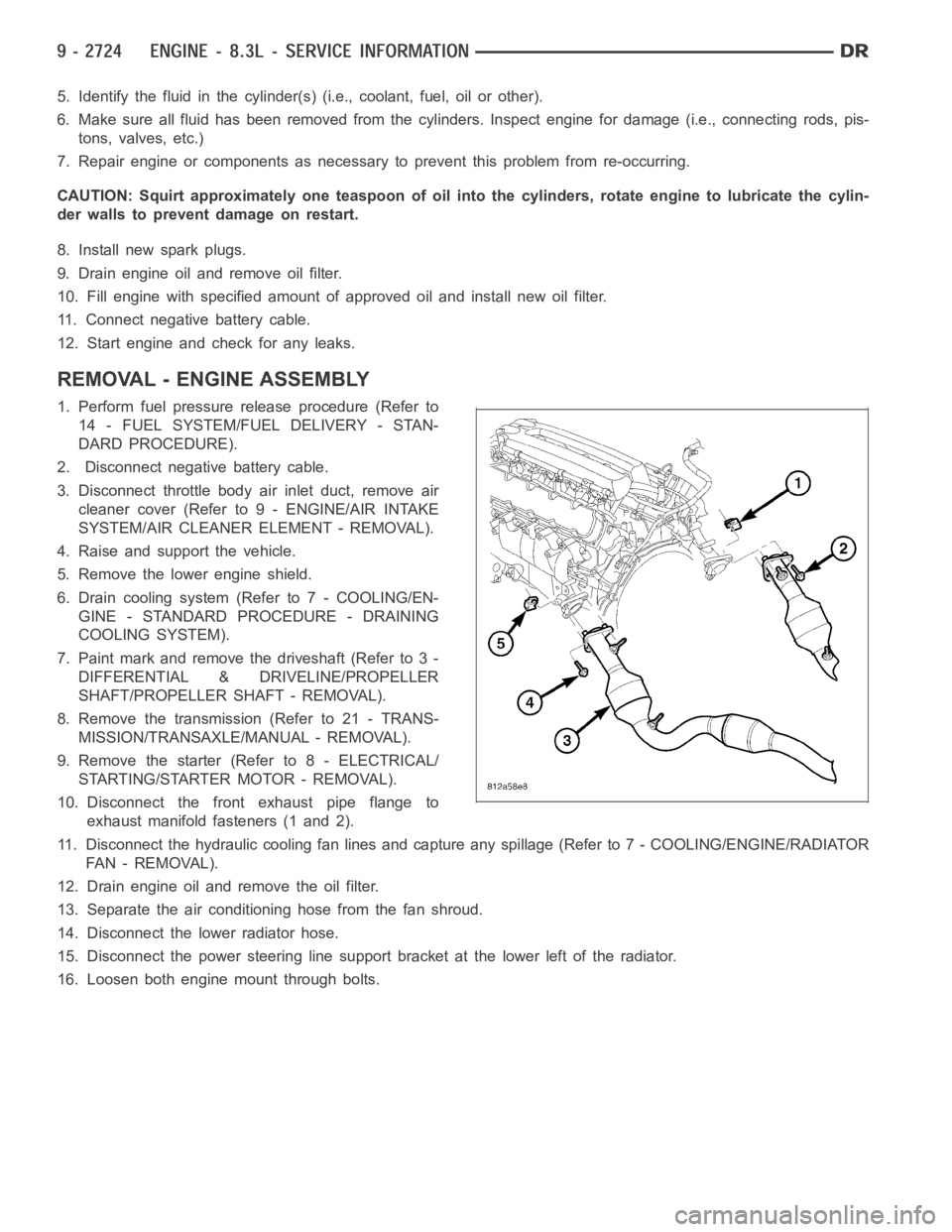
10. Disconnect the front exhaust pipe flange to
exhaust manifold fasteners (1 and 2).
11. Disconnect the hydraulic cooling fan lines and capture any spillage (Refer to 7 - COOLING/ENGINE/RADIATOR
FA N - R E M O VA L ) .
12. Drain engine oil and remove the oil filter.
13. Separate the air conditioning hose from the fan shroud.
14. Disconnect the lower radiator hose.
15. Disconnect the power steering line support bracket at the lower left ofthe radiator.
16. Loosen both engine mount through bolts.
Page 2040 of 5267
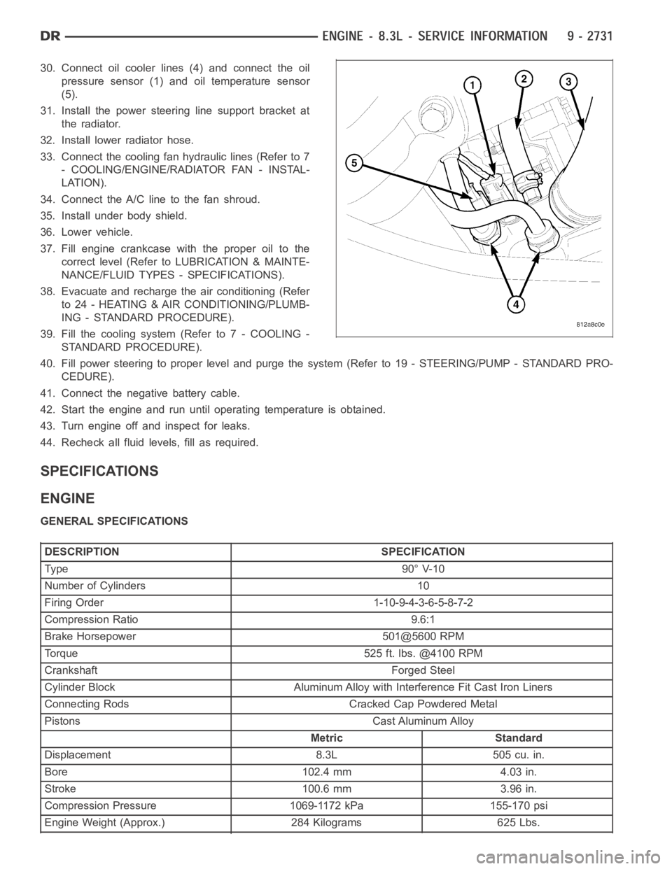
30. Connect oil cooler lines (4) and connect the oil
pressure sensor (1) and oil temperature sensor
(5).
31. Install the power steering line support bracket at
the radiator.
32. Install lower radiator hose.
33. Connect the cooling fan hydraulic lines (Refer to 7
- COOLING/ENGINE/RADIATOR FAN - INSTAL-
LATION).
34. Connect the A/C line to the fan shroud.
35. Install under body shield.
36. Lower vehicle.
37. Fill engine crankcase with the proper oil to the
correct level (Refer to LUBRICATION & MAINTE-
NANCE/FLUID TYPES - SPECIFICATIONS).
38. Evacuate and recharge the air conditioning (Refer
to 24 - HEATING & AIR CONDITIONING/PLUMB-
ING - STANDARD PROCEDURE).
39. Fill the cooling system (Refer to 7 - COOLING -
STANDARD PROCEDURE).
40. Fill power steering to proper leveland purge the system (Refer to 19 - STEERING/PUMP - STANDARD PRO-
CEDURE).
41. Connect the negative battery cable.
42. Start the engine and run until operating temperature is obtained.
43. Turn engine off and inspect for leaks.
44. Recheck all fluid levels, fill as required.
SPECIFICATIONS
ENGINE
GENERAL SPECIFICATIONS
DESCRIPTION SPECIFICATION
Ty pe 9 0° V-1 0
Number of Cylinders 10
Firing Order 1-10-9-4-3-6-5-8-7-2
Compression Ratio 9.6:1
Brake Horsepower 501@5600 RPM
Torque 525 ft. lbs. @4100 RPM
Crankshaft Forged Steel
Cylinder Block Aluminum Alloy with Interference Fit Cast Iron Liners
Connecting Rods Cracked Cap Powdered Metal
Pistons Cast Aluminum Alloy
Metric Standard
Displacement 8.3L 505 cu. in.
Bore 102.4 mm 4.03 in.
Stroke 100.6 mm 3.96 in.
Compression Pressure 1069-1172 kPa 155-170 psi
Engine Weight (Approx.) 284 Kilograms 625 Lbs.
Page 2062 of 5267
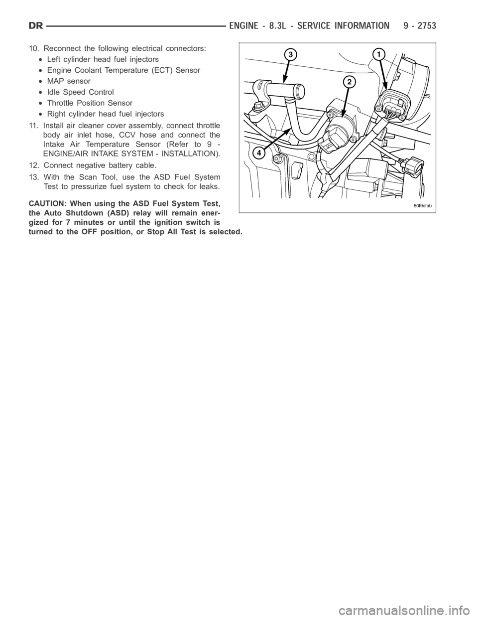
10. Reconnect the following electrical connectors:
Left cylinder head fuel injectors
Engine Coolant Temperature (ECT) Sensor
MAP sensor
Idle Speed Control
Throttle Position Sensor
Right cylinder head fuel injectors
11. Install air cleaner cover assembly, connect throttle
body air inlet hose, CCV hose and connect the
Intake Air Temperature Sensor (Refer to 9 -
ENGINE/AIR INTAKE SYSTEM - INSTALLATION).
12. Connect negative battery cable.
13. With the Scan Tool, use the ASD Fuel System
Test to pressurize fuel system to check for leaks.
CAUTION: When using the ASD Fuel System Test,
the Auto Shutdown (ASD) relay will remain ener-
gized for 7 minutes or until the ignition switch is
turned to the OFF position, or Stop All Test is selected.
Page 2067 of 5267
CLEANING
CLEANING AND INSPECTION
1. Before cleaning, check for leaks, damage and
cracks.
2. Clean cylinder head and oil passages.
3. Check cylinder head for flatness.
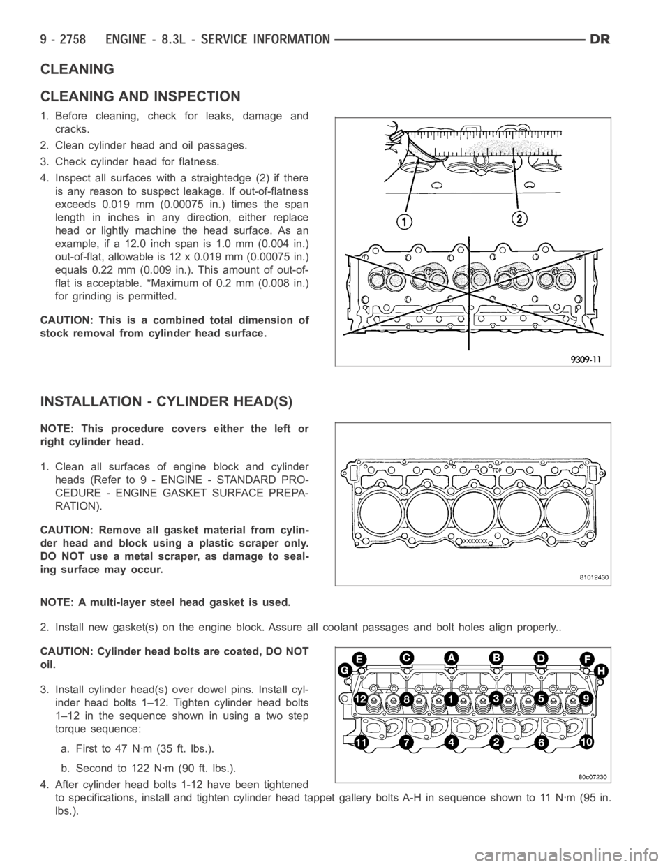
4. Inspect all surfaces with a straightedge (2) if there
is any reason to suspect leakage. If out-of-flatness
exceeds 0.019 mm (0.00075 in.) times the span
length in inches in any direction, either replace
head or lightly machine the head surface. As an
example, if a 12.0 inch span is 1.0 mm (0.004 in.)
out-of-flat, allowable is 12 x 0.019 mm (0.00075 in.)
equals 0.22 mm (0.009 in.). This amount of out-of-
flat is acceptable. *Maximum of 0.2 mm (0.008 in.)
for grinding is permitted.
CAUTION: This is a combined total dimension of
stock removal from cylinder head surface.
INSTALLATION - CYLINDER HEAD(S)
NOTE: This procedure covers either the left or
right cylinder head.
1. Clean all surfaces of engine block and cylinder
heads (Refer to 9 - ENGINE - STANDARD PRO-
CEDURE - ENGINE GASKET SURFACE PREPA-
RATION).
CAUTION: Remove all gasket material from cylin-
der head and block using a plastic scraper only.
DO NOT use a metal scraper, as damage to seal-
ing surface may occur.
NOTE: A multi-layer steel head gasket is used.
2. Install new gasket(s) on the engine block. Assure all coolant passages and bolt holes align properly..
CAUTION: Cylinder head bolts are coated, DO NOT
oil.
3. Install cylinder head(s) over dowel pins. Install cyl-
inder head bolts 1–12. Tighten cylinder head bolts
1–12 in the sequence shown in using a two step
torque sequence:
a. Firstto47Nꞏm(35ft.lbs.).
b. Second to 122 Nꞏm (90 ft. lbs.).
4. After cylinder head bolts 1-12 have been tightened
to specifications, install and tighten cylinder head tappet gallery bolts A-H in sequence shown to 11 Nꞏm (95 in.
lbs.).