2006 DODGE RAM SRT-10 check engine
[x] Cancel search: check enginePage 1978 of 5267
18. Start engine and check for oil leaks.
Page 1979 of 5267
SEAL - CRANKSHAFT OIL - REAR
REMOVAL
1. Disconnect the battery negative cables.
2. Remove the transmission and transfer case (if
equipped).
3. Remove the clutch cover and disc (if manual trans-
mission equipped) (Refer to 6 - CLUTCH/CLUTCH
DISC - REMOVAL).
4. Remove the flywheel or converter drive plate.
5. Remove the flywheel adapter plate.
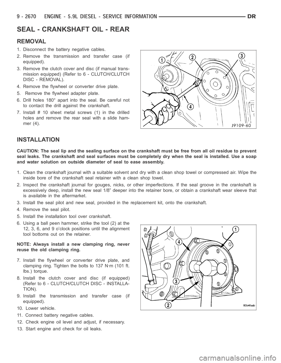
6. Drill holes 180° apart into the seal. Be careful not
to contact the drill against the crankshaft.
7. Install # 10 sheet metalscrews (1) in the drilled
holes and remove the rear seal with a slide ham-
mer (4).
INSTALLATION
CAUTION: The seal lip and the sealing surface on the crankshaft must be freefrom all oil residue to prevent
seal leaks. The crankshaft and seal surfaces must be completely dry when the seal is installed. Use a soap
and water solution on outside diameter of seal to ease assembly.
1. Clean the crankshaft journal with a suitable solvent and dry with a cleanshop towel or compressed air. Wipe the
inside bore of the crankshaft seal retainer with a clean shop towel.
2. Inspect the crankshaft journal forgouges, nicks, or other imperfections. If the seal groove in the crankshaft is
excessively deep, install the new seal 1/8” deeper into the retainer bore,or obtain a crankshaft wear sleeve that
is available in the aftermarket.
3. Install the seal pilot and new seal, provided in the replacement kit, onto the crankshaft.
4. Remove the seal pilot.
5. Install the installation tool over crankshaft.
6. Using a ball peen hammer, strike the tool (2) at the
12, 3, 6, and 9 o’clock positions until the alignment
tool bottoms out on the retainer.
NOTE: Always install a new clamping ring, never
reuse the old clamping ring.
7. Install the flywheel or converter drive plate, and
clamping ring. Tighten the bolts to 137 Nꞏm (101 ft.
lbs.) torque.
8. Install the clutch cover and disc (if equipped)
(Refer to 6 - CLUTCH/CLUTCH DISC - INSTALLA-
TION).
9. Install the transmission and transfer case (if
equipped).
10. Lower vehicle.
11. Connect battery negative cables.
12. Check engine oil level and adjust, if necessary.
13. Start engine and check for oil leaks.
Page 1981 of 5267
CAUTION: The seal lip and the sealing surface on
the crankshaft must be free from all oil residue to
prevent seal leaks. The crankshaft and seal sur-
faces must be completely dry when the seal is
installed. Use a soap and water solution on out-
side diameter of seal to ease assembly.
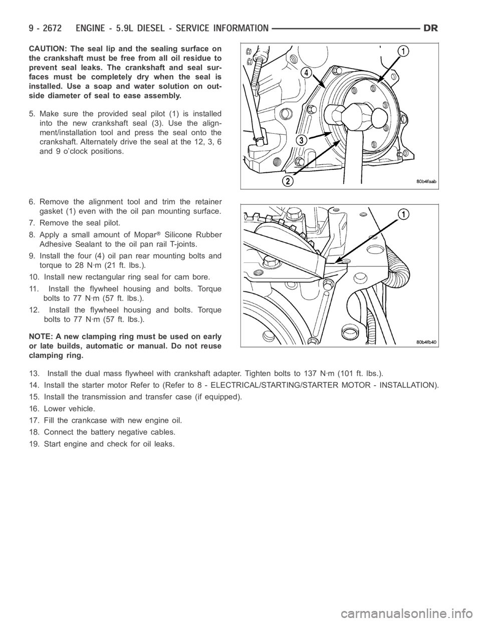
5. Make sure the provided seal pilot (1) is installed
into the new crankshaft seal (3). Use the align-
ment/installation tool and press the seal onto the
crankshaft. Alternately drive the seal at the 12, 3, 6
and 9 o’clock positions.
6. Remove the alignment tool and trim the retainer
gasket (1) even with the oil pan mounting surface.
7. Remove the seal pilot.
8. Apply a small amount of Mopar
Silicone Rubber
Adhesive Sealant to the oil pan rail T-joints.
9. Install the four (4) oil pan rear mounting bolts and
torque to 28 Nꞏm (21 ft. lbs.).
10. Install new rectangular ring seal for cam bore.
11. Install the flywheel housing and bolts. Torque
boltsto77Nꞏm(57ft.lbs.).
12. Install the flywheel housing and bolts. Torque
boltsto77Nꞏm(57ft.lbs.).
NOTE: A new clamping ring must be used on early
or late builds, automatic or manual. Do not reuse
clamping ring.
13. Install the dual mass flywheel with crankshaft adapter. Tighten boltsto 137 Nꞏm (101 ft. lbs.).
14. Install the starter motor Refer to (Refer to 8 - ELECTRICAL/STARTING/STA R T E R M O TO R - I N S TA L L AT I O N ) .
15. Install the transmission and transfer case (if equipped).
16. Lower vehicle.
17. Fill the crankcase with new engine oil.
18. Connect the battery negative cables.
19. Start engine and check for oil leaks.
Page 1987 of 5267
REMOVAL
1. Disconnect the battery cables.
2. Remove the cylinder head (Refer to 9 - ENGINE/CYLINDER HEAD - REMOVAL).
3. Remove the oil pan and suction tube (Refer to 9 - ENGINE/LUBRICATION/OILPA N - R E M O VA L ) .
4. Remove bolts and the block stiffener.
5. Using Miller Tool 7471-B crankshaft barring tool, rotate the crankshaft so all of the pistons are below TDC.
6. Before removing the piston(s) from the bore(s):
a. Remove any carbon ridge formations or deposits at the top of the bore witha dull scraper or soft wire brush.
b. If cylinder bore wear ridges are found, use a ridge reamer to cut the ridgefrom the bore. DO NOT remove
more metal than necessaryto remove the ridge.
7. Remove the J-jet cooling nozzles.
NOTE: If cylinders have ridges, the cylinders are oversize and will more than likely need boring.
8. Using a hammer and steel stamp, stamp the cylinder number in the top of eachpiston.Thefrontofthepiston
is identified by a stamping on the top of the piston. DO NOT stamp in the outside 5 mm (.197 in.) of the piston
diameter. DO NOT stamp over the piston pin.
9. Mark the connecting rod and cap with the corresponding cylinder numbers.
10. Remove the connecting rod bolts and rod caps. Use care so the cylinder bores and connecting rods are not
damaged.
11. Use a hammer handle or similar object to push the piston and connecting rod through the cylinder bore.
12. Store the piston/rod assemblies in a rack.
CLEANING—PISTON AND CONNECTING ROD
CAUTION: DO NOT use bead blast to clean the pistons. DO NOT clean the pistonsandrodsinanacidtank.
PISTON
Clean the pistons and pins in a suitable solvent, rinse in hot water and blowdry with compressed air. Soaking the
pistons over night will loosen most of the carbon build up. De-carbon the ringgrooveswithabrokenpistonringand
again clean the pistons in solvent. Rinse in hot water and blow dry with compressed air.
CONNECTING ROD
Clean the connecting rods in a suitable solvent, rinse in hot water and blowdry with compressed air.
INSPECTION
INSPECTION - PISTONS
PISTON SKIRT DIAMETER (MIN.)
101.775 mm (4.006 in. )
Inspect the pistons for damage and excessive wear. Check top of the piston,ring grooves, skirt and pin bore. Mea-
sure the piston skirt diameter. If the piston is out of limits, replace the piston.
Page 1990 of 5267
a. The connecting rod split/face mustface toward the same side as the piston notch feature on the skirt. The
split face will face toward the exhaust side of the engine if properly installed.
11. Install the rod cap and bolts to the connecting rod. Tighten the connecting rod bolts evenly in 3 steps.
Tighten the bolts to 30 Nꞏm (22 ft. lbs.) torque.
Tighten the bolts to 60 Nꞏm (44 ft. lbs.) torque.
Rotate 60° clockwise.
12. The crankshaft must rotate freely. Check for freedom of rotation as thecaps are installed. If the crankshaft does
not rotate freely, check the installation of the rod bearing and the bearingsize.
13. Measure the side clearance between the connecting rod and the crankshaft. DO NOT measure the clearance
between the cap and crankshaft.
14. Install J-jet piston cooling nozzles.
15. Install block stiffener. Torque to 43 Nꞏm (32 ft. lbs.).
16. Install the suction tube and oil pan (Refer to 9 - ENGINE/LUBRICATION/OIL PAN - INSTALLATION).
17. Install the cylinder head onto the engine (Refer to 9 - ENGINE/CYLINDERHEAD - INSTALLATION).
18. Install a new filter and fill the crankcase with new engine oil.Prefill the filter with clean oil.
19. Connect the battery negative cables and start engine.
Page 2002 of 5267
OIL
STANDARD PROCEDURE
STANDARD PROCEDURE - ENGINE OIL LEVEL
CAUTION: Do not overfill crankcase with engine
oil, oil foaming and oil pressure loss can result.
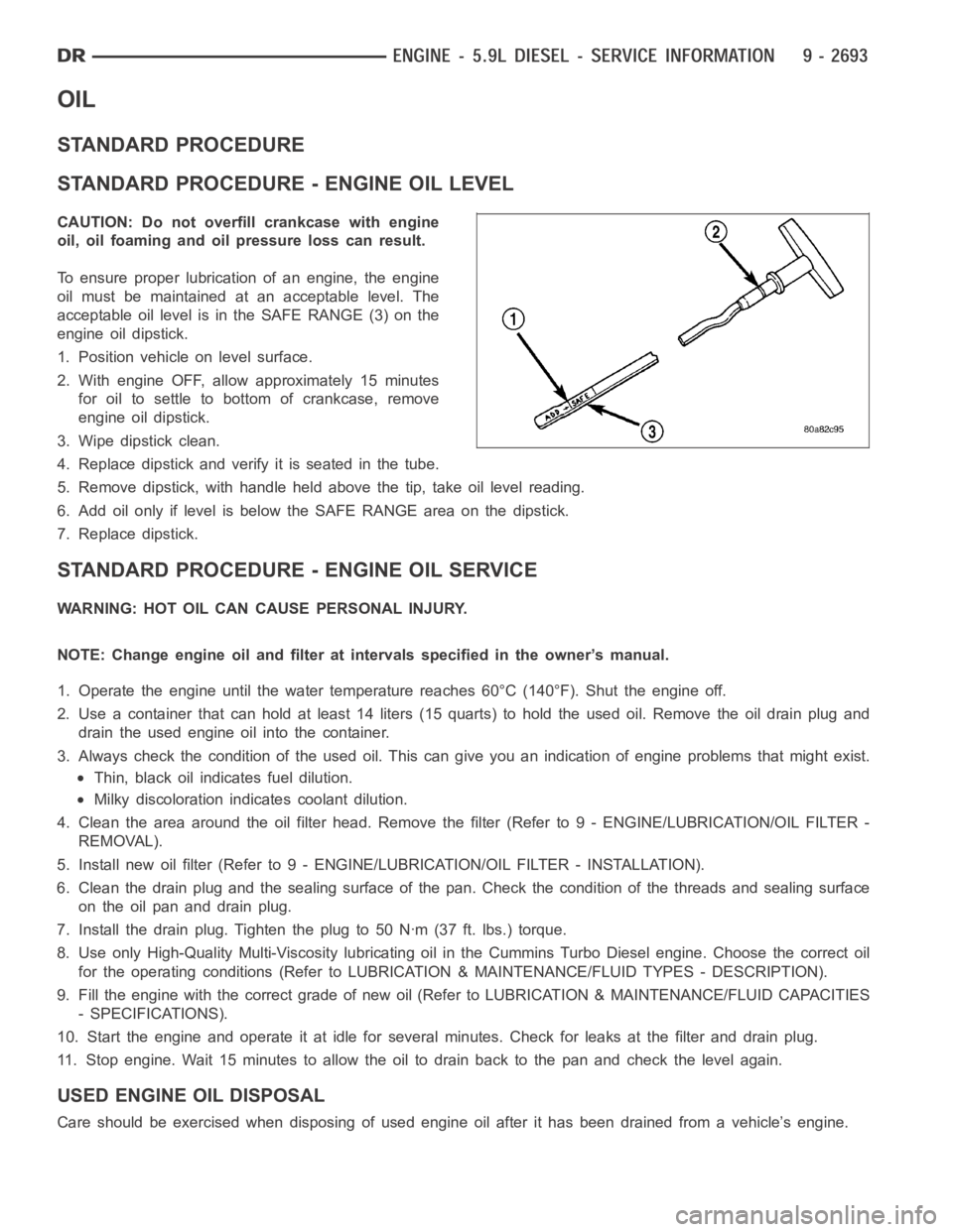
To ensure proper lubrication of an engine, the engine
oil must be maintained at an acceptable level. The
acceptable oil level is in the SAFE RANGE (3) on the
engine oil dipstick.
1. Position vehicle on level surface.
2. With engine OFF, allow approximately 15 minutes
for oil to settle to bottom of crankcase, remove
engine oil dipstick.
3. Wipe dipstick clean.
4. Replace dipstick and verify it is seated in the tube.
5. Remove dipstick, with handle held above the tip, take oil level reading.
6. Add oil only if level is below the SAFE RANGE area on the dipstick.
7. Replace dipstick.
STANDARD PROCEDURE - ENGINE OIL SERVICE
WARNING: HOT OIL CAN CAUSE PERSONAL INJURY.
NOTE: Change engine oil and filter at intervals specified in the owner’s manual.
1. Operate the engine until the water temperature reaches 60°C (140°F). Shut the engine off.
2. Use a container that can hold at least 14 liters (15 quarts) to hold the used oil. Remove the oil drain plug and
drain the used engine oil into the container.
3. Always check the condition of the used oil. This can give you an indication of engine problems that might exist.
Thin, black oil indicates fuel dilution.
Milky discoloration indicates coolant dilution.
4. Clean the area around the oil filter head. Remove the filter (Refer to 9 - ENGINE/LUBRICATION/OIL FILTER -
REMOVAL).
5. Install new oil filter (Refer to 9 - ENGINE/LUBRICATION/OIL FILTER - INSTA L L AT I O N ) .
6. Clean the drain plug and the sealing surface of the pan. Check the condition of the threads and sealing surface
on the oil pan and drain plug.
7. Install the drain plug. Tighten the plug to 50 Nꞏm (37 ft. lbs.) torque.
8. Use only High-Quality Multi-Viscosity lubricating oil in the Cummins Turbo Diesel engine. Choose the correct oil
for the operating conditions (Refer to LUBRICATION & MAINTENANCE/FLUID TYPES - DESCRIPTION).
9. Fill the engine with the correct grade of new oil (Refer to LUBRICATION & MAINTENANCE/FLUID CAPACITIES
- SPECIFICATIONS).
10. Start the engine and operate it at idle for several minutes. Check for leaks at the filter and drain plug.
11. Stop engine. Wait 15 minutes to allow the oil to drain back to the pan and check the level again.
USED ENGINE OIL DISPOSAL
Care should be exercised when disposing of used engine oil after it has beendrained from a vehicle’s engine.
Page 2003 of 5267
COOLER - ENGINE OIL & LINES
CLEANING
CLEANING AND INSPECTION
Clean the sealing surfaces.
Apply 483 kPa (70 psi) air pressure to the element to check for leaks. If the element leaks, replace the element.
Page 2005 of 5267
PA N - E N G I N E O I L
REMOVAL
1. Disconnect the battery negative cables.
2. Install engine support fixture # 8534.
3. Raise vehicle on hoist.
4. Disconnect starter cables from starter motor.
5. Remove transmission and transfer case (if equipped).
6. Remove flywheel or flexplate.
7. Remove starter motor (Refer to 8 - ELECTRICAL/STARTING/STARTER MOTOR -REMOVAL) and transmission
adapter plate assembly.
WARNING: HOT OIL CAN CAUSE PERSONAL INJURY.
8. Drain the engine oil (Refer to 9 - ENGINE/LUBRICATION/OIL - STANDARD PROCEDURE).
9. Install the oil pan drain plug if sealing surface is not damaged and tighten to 50 Nꞏm (37 ft. lbs.) torque.
10. Remove oil pan bolts, break the pan to block seal, and lower pan slightlyandremoveoilsuctiontubefasteners.
11. Remove oil pan and suction tube.
CLEANING
Remove all gasket material from the oil pan and cylinder block sealing surfaces. Extra effort may be required
around T-joint areas. Clean oil pan and flush suction tube with a suitable solvent.
INSPECTION
Inspect the oil pan, suction tube, and tube braces for cracks and damage. Replace any defective component.
Inspect the oil drain plug and drain hole threads. Inspect the oil pan sealing surface for straightness. Repair any
minor imperfections with a ball-peen hammer. Do not attempt to repair an oil pan by welding.
INSTALLATION
1. Fill the T-joint between the pan rail/gear housing and pan rail/rear seal retainer with sealant. Use MoparSilicone
Rubber Adhesive Sealant or equivalent.
2. Place suction tube in oil pan and guide them into place. Slide oil pan gasket into postion.Using a new tube to
block gasket, install and tighten the suction tube bolts by hand. Startingwith the oil pump inlet bolts, tighten the
bolts to 24 Nꞏm (18 ft. lbs.) torque. Tighten the remaining tube brace boltsto 43 Nꞏm (32 ft. lbs.) torque.
3. Starting in the center and working outward, tighten the oil pan bolts to 28Nꞏm(21ft.lbs.)torque.
4. Install the flywheel housing assembly with the starter motor attached and tighten bolts to 77 Nꞏm (57 ft. lbs.)
torque.
5. Connect starter motor cables.
NOTE: A new clamping ring must be used on early or late builds, automatic or manual. Do not reuse clamp-
ing ring.
6. Install the flywheel to crankshaft adapter. Torque to 137 Nꞏm (101 ft. lbs.).
7. Install transmission and transfer case (if equipped).
8. Lower vehicle.
9. Remove the engine support fixture # 8534.
10. Install battery negative cables.
11. Fill the crankcase with new engine oil.
12. Start engine and check for leaks. Stop engine, check oil level, and adjust, if necessary.