2006 DODGE RAM SRT-10 check engine
[x] Cancel search: check enginePage 1914 of 5267
3. Place a shop towel around the fuel injectors to catch any fluid that may possibly be under pressure in the cyl-
inder head. Remove the fuel injectors (Refer to 14 - FUEL SYSTEM/FUEL INJECTION/FUEL INJECTOR -
REMOVAL).
4. With all injectors removed, rotatethe crankshaft using the crankshaftbarring tool (PN 7471–B).
5. Identify the fluid in the cylinders (coolant, fuel, oil, etc.).
6. Be sure all fluid has been removed from the cylinders.
7. Repair engine or components as necessary to prevent this problem from occurring again.
8. Squirt a small amount of engine oil into the cylinders to lubricate the walls. This will prevent damage on restart.
9. Install fuel injectors (Refer to 14 - FUEL SYSTEM/FUEL INJECTION/FUEL INJECTOR - INSTALLATION).
10. Drain engine oil. Remove and discard the oil filter (Refer to 9 - ENGINE/LUBRICATION/OIL FILTER -
REMOVAL).
11. Installthedrainplug.Tightentheplugto50Nꞏm(37ft.lbs.)torque.
12. Install a new oil filter (Refer to 9 - ENGINE/LUBRICATION/OIL FILTER - INSTALLATION).
13. Fill engine crankcase with the specified amount and grade of oil (Referto LUBRICATION & MAINTENANCE/
FLUID TYPES - SPECIFICATIONS).
14. Connect the negative cable(s) to the battery.
15. Start the engine and check for any leaks.
REMOVAL - ENGINE
1. Disconnect both battery negative cables.
2. Disconnect engine grid heater harness at grid
heater relays.
3. Disconnect electrical connections from rear of alter-
nator.
4. Recover A/C refrigerant. (Refer to 24 - HEATING &
AIR CONDITIONING/PLUMBING - STANDARD
PROCEDURE).
5. Raise vehicle on a hoist.
6. Drain engine coolant (Refer to 7 - COOLING -
STANDARD PROCEDURE).
7. Remove engine oil drain plug and drain engine oil.
8. Reinstall drain plug. Tighten to 50 Nꞏm (37 ft. lbs.)
torque.
9. Lower the vehicle.
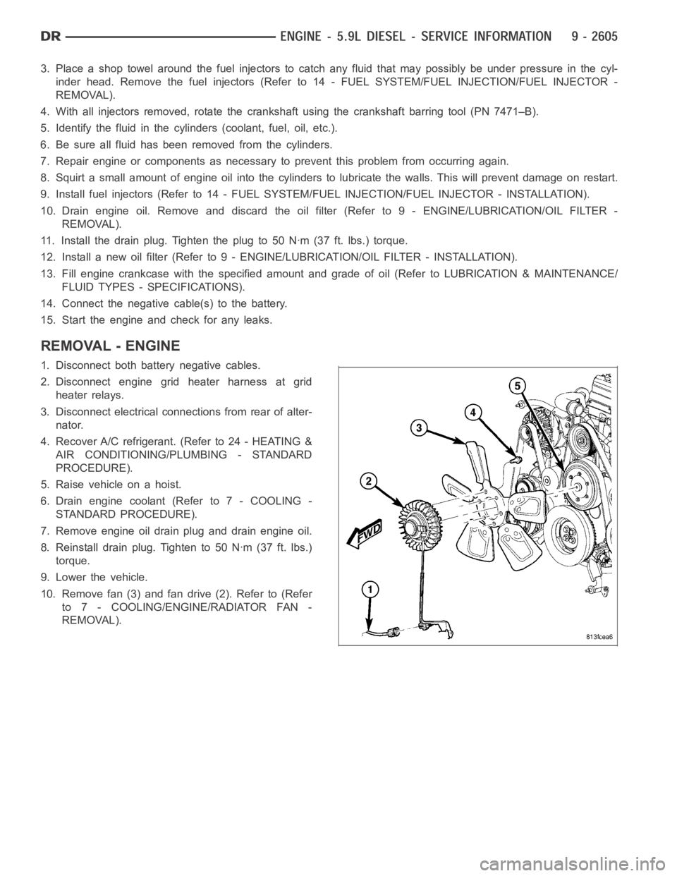
10. Remove fan (3) and fan drive (2). Refer to (Refer
to 7 - COOLING/ENGINE/RADIATOR FAN -
REMOVAL).
Page 1919 of 5267
INSTALLATION - ENGINE
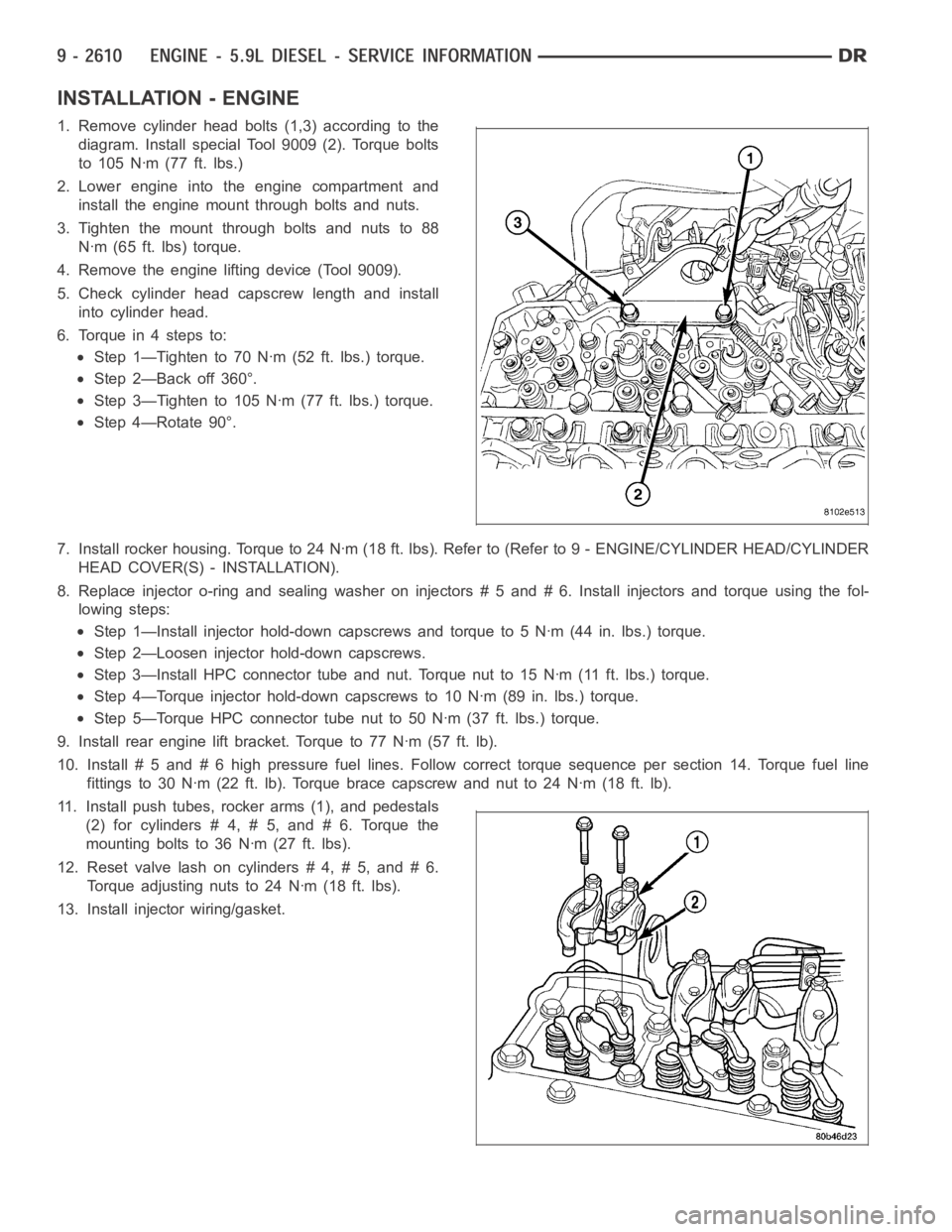
1. Remove cylinder head bolts (1,3) according to the
diagram. Install special Tool 9009 (2). Torque bolts
to 105 Nꞏm (77 ft. lbs.)
2. Lower engine into the engine compartment and
install the engine mount through bolts and nuts.
3. Tighten the mount through bolts and nuts to 88
Nꞏm (65 ft. lbs) torque.
4. Remove the engine lifting device (Tool 9009).
5. Check cylinder head capscrew length and install
into cylinder head.
6. Torque in 4 steps to:
Step 1—Tighten to 70 Nꞏm (52 ft. lbs.) torque.
Step 2—Back off 360°.
Step 3—Tighten to 105 Nꞏm (77 ft. lbs.) torque.
Step 4—Rotate 90°.
7. Install rocker housing. Torque to 24 Nꞏm (18 ft. lbs). Refer to (Refer to 9- ENGINE/CYLINDER HEAD/CYLINDER
HEAD COVER(S) - INSTALLATION).
8. Replace injector o-ring and sealing washer on injectors # 5 and # 6. Install injectors and torque using the fol-
lowing steps:
Step 1—Install injector hold-down capscrews and torque to 5 Nꞏm (44 in. lbs.) torque.
Step 2—Loosen injector hold-down capscrews.
Step 3—Install HPC connector tube and nut. Torque nut to 15 Nꞏm (11 ft. lbs.)torque.
Step 4—Torque injector hold-down capscrews to 10 Nꞏm (89 in. lbs.) torque.
Step 5—Torque HPC connector tube nut to 50 Nꞏm (37 ft. lbs.) torque.
9. Install rear engine lift bracket. Torque to 77 Nꞏm (57 ft. lb).
10. Install # 5 and # 6 high pressure fuel lines. Follow correct torque sequence per section 14. Torque fuel line
fittings to 30 Nꞏm (22 ft. lb). Torque brace capscrew and nut to 24 Nꞏm (18 ft.lb).
11. Install push tubes, rocker arms (1), and pedestals
(2) for cylinders # 4, # 5, and # 6. Torque the
mounting bolts to 36 Nꞏm (27 ft. lbs).
12. Reset valve lash on cylinders # 4, # 5, and # 6.
Torque adjusting nuts to 24 Nꞏm (18 ft. lbs).
13. Install injector wiring/gasket.
Page 1937 of 5267
INSPECTION—PUSHRODS
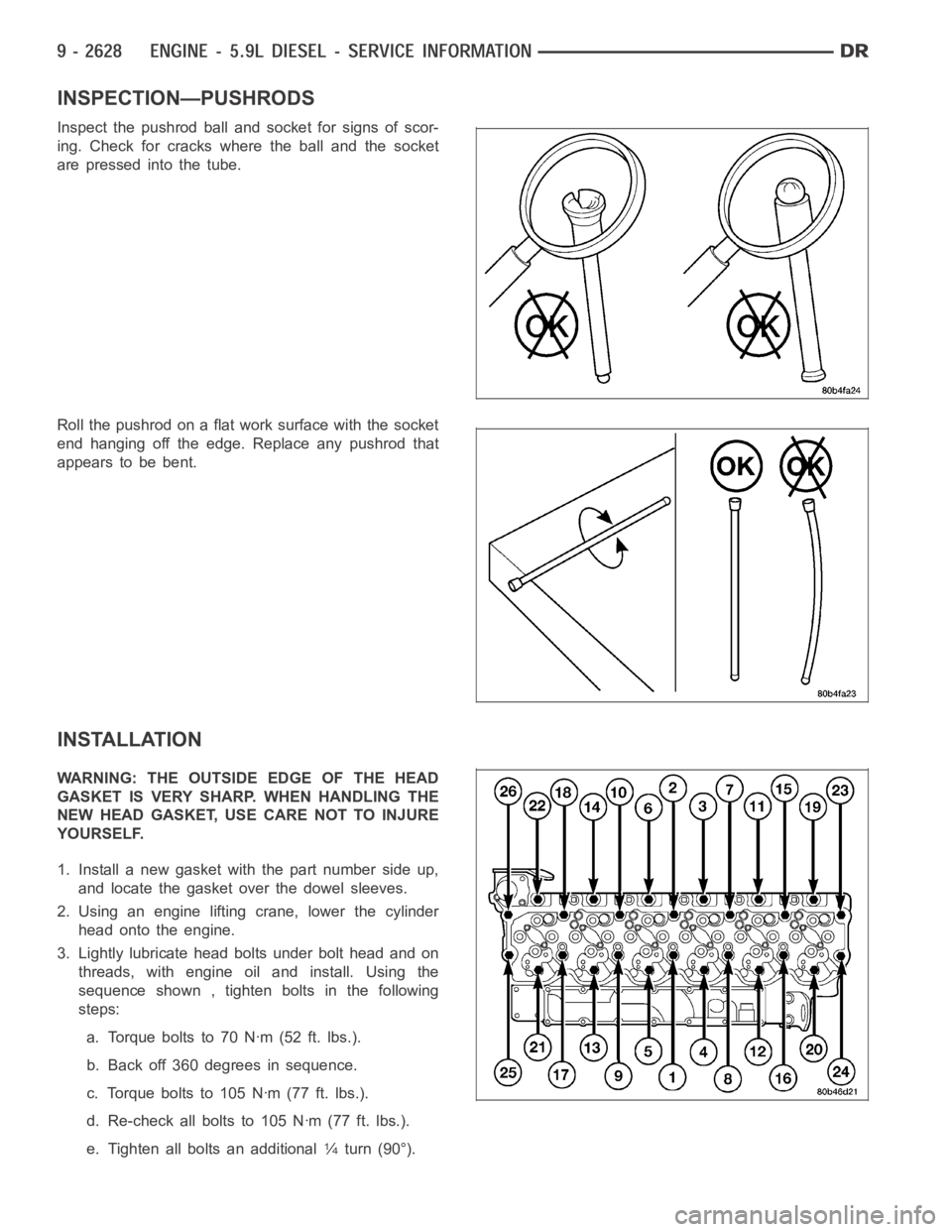
Inspect the pushrod ball and socket for signs of scor-
ing. Check for cracks where the ball and the socket
are pressed into the tube.
Roll the pushrod on a flat work surface with the socket
end hanging off the edge. Replace any pushrod that
appears to be bent.
INSTALLATION
WARNING: THE OUTSIDE EDGE OF THE HEAD
GASKET IS VERY SHARP. WHEN HANDLING THE
NEW HEAD GASKET, USE CARE NOT TO INJURE
YOURSELF.
1. Install a new gasket with the part number side up,
and locate the gasket over the dowel sleeves.
2. Using an engine lifting crane, lower the cylinder
head onto the engine.
3. Lightly lubricate head bolts under bolt head and on
threads, with engine oil and install. Using the
sequence shown , tighten bolts in the following
steps:
a. Torqueboltsto70Nꞏm(52ft.lbs.).
b. Back off 360 degrees in sequence.
c. Torque bolts to 105 Nꞏm (77 ft. lbs.).
d. Re-check all bolts to 105 Nꞏm (77 ft. lbs.).
e. Tighten all bolts an additional
1⁄4turn (90°).
Page 1940 of 5267
NOTE: Do not reuse the clamp for the exhaust pipe to turbocharger elbow connection.
48. Install the exhaust pipe to turbocharger elbow using a new clamp. Torque bolts to 11 Nꞏm (100 in. lbs.).
49. Lower vehicle.
50. Fill engine coolant (Refer to 7 - COOLING - STANDARD PROCEDURE).
51. Start engine and check for leaks.
Page 1953 of 5267
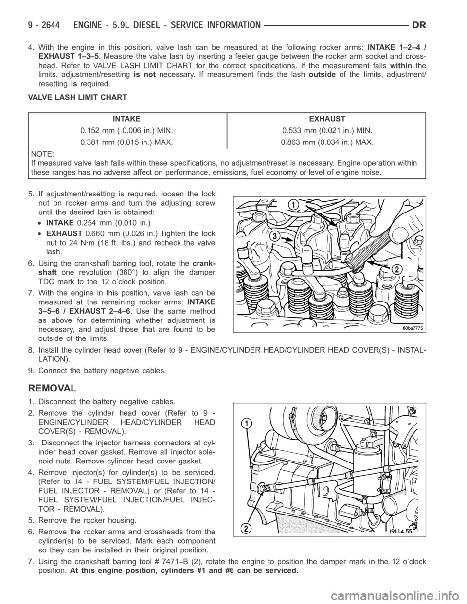
4. With the engine in this position, valve lash can be measured at the following rocker arms:INTAKE 1–2–4 /
EXHAUST 1–3–5. Measure the valve lash by inserting a feeler gauge between the rocker arm socket and cross-
head. Refer to VALVE LASH LIMIT CHART for the correct specifications. If the measurement fallswithinthe
limits, adjustment/resettingis notnecessary. If measurement finds the lashoutsideof the limits, adjustment/
resettingisrequired.
VALVE LASH LIMIT CHART
INTAKE EXHAUST
0.152 mm ( 0.006 in.) MIN. 0.533 mm (0.021 in.) MIN.
0.381 mm (0.015 in.) MAX. 0.863 mm (0.034 in.) MAX.
NOTE:
If measured valve lash falls within these specifications, no adjustment/reset is necessary. Engine operation within
these ranges has no adverse affect on performance, emissions, fuel economy or level of engine noise.
5. If adjustment/resetting is required, loosen the lock
nut on rocker arms and turn the adjusting screw
until the desired lash is obtained:
INTAKE0.254 mm (0.010 in.)
EXHAUST0.660 mm (0.026 in.) Tighten the lock
nut to 24 Nꞏm (18 ft. lbs.) and recheck the valve
lash.
6. Using the crankshaft barring tool, rotate thecrank-
shaftone revolution (360°) to align the damper
TDC mark to the 12 o’clock position.
7. With the engine in this position, valve lash can be
measured at the remaining rocker arms:INTAKE
3–5–6 / EXHAUST 2–4–6. Use the same method
as above for determining whether adjustment is
necessary, and adjust those that are found to be
outside of the limits.
8. Install the cylinder head cover (Refer to 9 - ENGINE/CYLINDER HEAD/CYLINDER HEAD COVER(S) - INSTAL-
LATION).
9. Connect the battery negative cables.
REMOVAL
1. Disconnect the battery negative cables.
2. Remove the cylinder head cover (Refer to 9 -
ENGINE/CYLINDER HEAD/CYLINDER HEAD
COVER(S) - REMOVAL).
3. Disconnect the injector harness connectors at cyl-
inder head cover gasket. Remove all injector sole-
noid nuts. Remove cylinder head cover gasket.
4. Remove injector(s) for cylinder(s) to be serviced.
(Refer to 14 - FUEL SYSTEM/FUEL INJECTION/
FUELINJECTOR-REMOVAL)or(Referto14-
FUEL SYSTEM/FUEL INJECTION/FUEL INJEC-
TOR - REMOVAL).
5. Remove the rocker housing.
6. Remove the rocker arms and crossheads from the
cylinder(s) to be serviced. Mark each component
so they can be installed in their original position.
7. Using the crankshaft barring tool # 7471–B (2), rotate the engine to position the damper mark in the 12 o’clock
position.At this engine position, cylinders #1 and #6 can be serviced.
Page 1958 of 5267
Push Rods
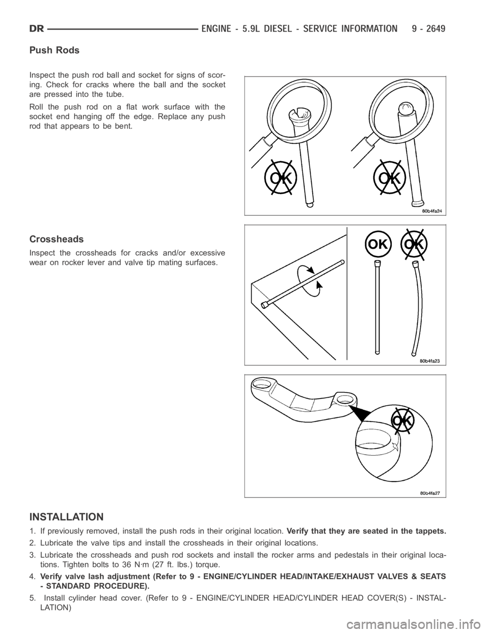
Inspect the push rod ball and socket for signs of scor-
ing. Check for cracks where the ball and the socket
are pressed into the tube.
Roll the push rod on a flat work surface with the
socket end hanging off the edge. Replace any push
rod that appears to be bent.
Crossheads
Inspect the crossheads for cracks and/or excessive
wear on rocker lever and valve tip mating surfaces.
INSTALLATION
1. If previously removed, install the push rods in their original location.Verify that they are seated in the tappets.
2. Lubricate the valve tips and install the crossheads in their original locations.
3. Lubricate the crossheads and push rod sockets and install the rocker arms and pedestals in their original loca-
tions. Tighten bolts to 36 Nꞏm (27 ft. lbs.) torque.
4.Verify valve lash adjustment (Refer to 9 - ENGINE/CYLINDER HEAD/INTAKE/EXHAUST VALVES & SEATS
- STANDARD PROCEDURE).
5. Install cylinder head cover. (Refer to 9 - ENGINE/CYLINDER HEAD/CYLINDER HEAD COVER(S) - INSTAL-
LATION)
Page 1961 of 5267
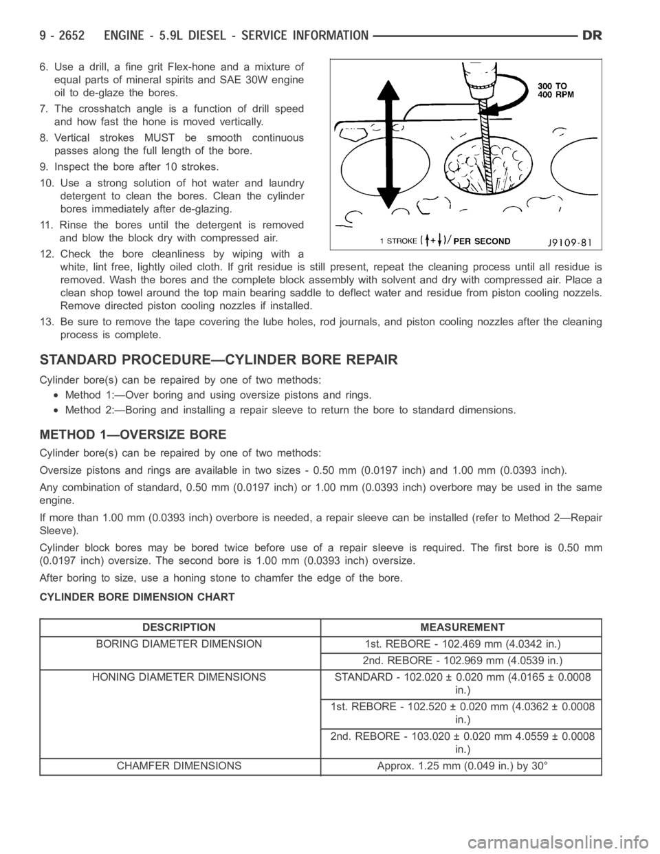
6. Use a drill, a fine grit Flex-hone and a mixture of
equal parts of mineral spirits and SAE 30W engine
oil to de-glaze the bores.
7. The crosshatch angle is a function of drill speed
and how fast the hone is moved vertically.
8. Vertical strokes MUST be smooth continuous
passes along the full length of the bore.
9. Inspect the bore after 10 strokes.
10. Use a strong solution of hot water and laundry
detergent to clean the bores. Clean the cylinder
bores immediately after de-glazing.
11. Rinse the bores until the detergent is removed
and blow the block dry with compressed air.
12. Check the bore cleanliness by wiping with a
white, lint free, lightly oiled cloth. If grit residue is still present, repeat the cleaning process until all residue is
removed. Wash the bores and the complete block assembly with solvent and dry with compressed air. Place a
clean shop towel around the top main bearing saddle to deflect water and residue from piston cooling nozzels.
Remove directed piston cooling nozzles if installed.
13. Be sure to remove the tape covering the lube holes, rod journals, and piston cooling nozzles after the cleaning
process is complete.
STANDARD PROCEDURE—CYLINDER BORE REPAIR
Cylinder bore(s) can be repaired by one of two methods:
Method 1:—Over boring and using oversize pistons and rings.
Method 2:—Boring and installing a repair sleeve to return the bore to standard dimensions.
METHOD 1—OVERSIZE BORE
Cylinder bore(s) can be repaired by one of two methods:
Oversize pistons and rings are available in two sizes - 0.50 mm (0.0197 inch) and 1.00 mm (0.0393 inch).
Any combination of standard, 0.50 mm (0.0197 inch) or 1.00 mm (0.0393 inch)overbore may be used in the same
engine.
If more than 1.00 mm (0.0393 inch) overbore is needed, a repair sleeve can beinstalled (refer to Method 2—Repair
Sleeve).
Cylinder block bores may be bored twice before use of a repair sleeve is required. The first bore is 0.50 mm
(0.0197 inch) oversize. The second bore is 1.00 mm (0.0393 inch) oversize.
After boring to size, use a honing stone to chamfer the edge of the bore.
CYLINDER BORE DIMENSION CHART
DESCRIPTION MEASUREMENT
BORING DIAMETER DIMENSION 1st. REBORE - 102.469 mm (4.0342 in.)
2nd. REBORE - 102.969 mm (4.0539 in.)
HONING DIAMETER DIMENSIONS STANDARD - 102.020 ± 0.020 mm (4.0165 ± 0.0008
in.)
1st. REBORE - 102.520 ± 0.020 mm (4.0362 ± 0.0008
in.)
2nd. REBORE - 103.020 ± 0.020 mm 4.0559 ± 0.0008
in.)
CHAMFER DIMENSIONS Approx. 1.25 mm (0.049 in.) by 30°
Page 1971 of 5267
12. Install gear housing cover (Refer to 9 - ENGINE/VALVE TIMING/GEAR HOUSING COVER - INSTALLATION).
Install front crankshaft dust seal.
13. Install the crankshaft damper with the speed indicator ring (Refer to 9- ENGINE/ENGINE BLOCK/VIBRATION
DAMPER - INSTALLATION).
14. Install the fan support/hub assembly Refer to (Refer to 7 - COOLING/ENGINE/RADIATOR FAN - INSTALLA-
TION).
15. Install the power steering pump.
16. Install accessory drive belt tensioner. Torque bolt to 43 Nꞏm (32 ft. lbs.).
17. Install the accessory drive belt (Refer to 7 - COOLING/ACCESSORY DRIVE/DRIVE BELTS - INSTALLATION).
18. Install the charge air cooler (with a/c condenser and auxiliary transmission oil cooler, if equipped) and tighten
the mounting bolts to 2 Nꞏm (17 in. lbs.) torque.
19. Connect charge air cooler inlet and outlet pipes. Tighten clamps to 11 Nꞏm (95 in. lbs.) torque.
20. Install the radiator upper support panel.
21. Close radiator petcock and lower the radiator into the engine compartment. Tighten the mounting bolts to 11
Nꞏm (95 in. lbs.) torque.
22. Raise vehicle on hoist.
23. Connect radiator lower hose and install clamp.
24. Connect transmission auxiliary oil cooler lines (if equipped).
25. Lower vehicle.
26. Install the fandrive/shroud assembly. (Refer to 7 - COOLING/ENGINE/RADIATOR FAN - INSTALLATION)
27. Install the coolant recovery and windshield washer fluid reservoirs to the fan shroud.
28. Connect the coolant recovery hose to the radiator filler neck.
29. Add engine coolant (Refer to 7 - COOLING - STANDARD PROCEDURE).
30. Charge A/C system with refrigerant (if A/C equipped) (Refer to 24 - HEATING & AIR CONDITIONING/PLUMB-
ING - STANDARD PROCEDURE).
31. Connect the battery negative cables.
32. Start engine and check for engine oil and coolant leaks.