2006 DODGE RAM SRT-10 check engine
[x] Cancel search: check enginePage 1726 of 5267
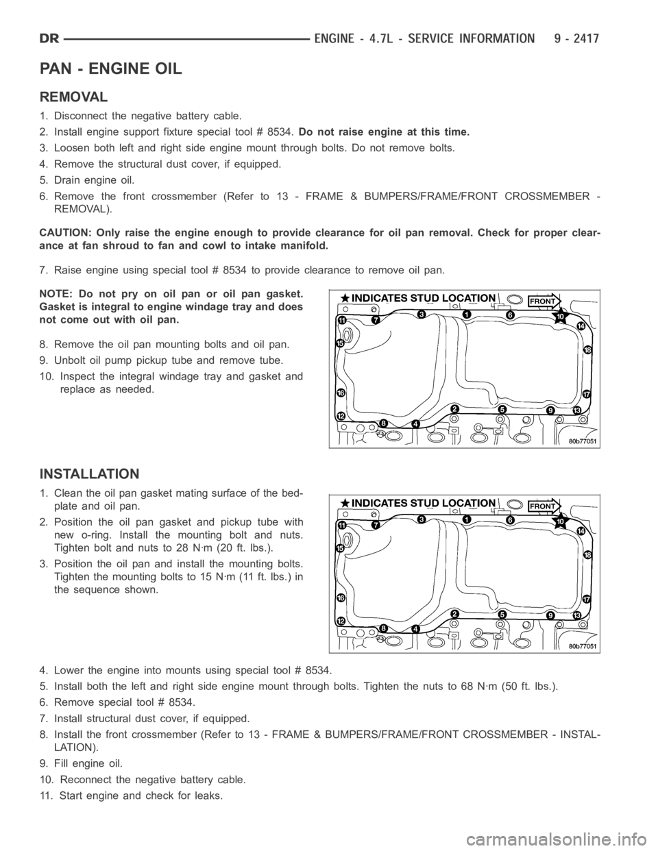
PA N - E N G I N E O I L
REMOVAL
1. Disconnect the negative battery cable.
2. Install engine support fixture special tool # 8534.Do not raise engine at this time.
3. Loosen both left and right side engine mount through bolts. Do not removebolts.
4. Remove the structural dust cover, if equipped.
5. Drain engine oil.
6. Remove the front crossmember (Refer to 13 - FRAME & BUMPERS/FRAME/FRONTCROSSMEMBER -
REMOVAL).
CAUTION: Only raise the engine enough to provide clearance for oil pan removal. Check for proper clear-
ance at fan shroud to fan and cowl to intake manifold.
7. Raise engine using special tool # 8534 to provide clearance to remove oilpan.
NOTE:Donotpryonoilpanoroilpangasket.
Gasket is integral to engine windage tray and does
not come out with oil pan.
8. Remove the oil pan mounting bolts and oil pan.
9. Unbolt oil pump pickup tube and remove tube.
10. Inspect the integral windage tray and gasket and
replace as needed.
INSTALLATION
1. Clean the oil pan gasket mating surface of the bed-
plate and oil pan.
2. Position the oil pan gasket and pickup tube with
new o-ring. Install the mounting bolt and nuts.
Tighten bolt and nuts to 28 Nꞏm (20 ft. lbs.).
3. Position the oil pan and install the mounting bolts.
Tighten the mounting bolts to 15 Nꞏm (11 ft. lbs.) in
the sequence shown.
4. Lower the engine into mounts using special tool # 8534.
5. Install both the left and right side engine mount through bolts. Tightenthenutsto68Nꞏm(50ft.lbs.).
6. Remove special tool # 8534.
7. Install structural dust cover, if equipped.
8. Install the front crossmember (Refer to 13 - FRAME & BUMPERS/FRAME/FRONT CROSSMEMBER - INSTAL-
LATION).
9. Fill engine oil.
10. Reconnect the negative battery cable.
11. Start engine and check for leaks.
Page 1727 of 5267
SWITCH - OIL PRESSURE
DESCRIPTION
DESCRIPTION
The 3 wire, solid-state engine oil pressure sensor (sending unit) is located in an engine oil pressure gallery.
DESCRIPTION
The 3–wire, electrical/mechanical engine oil pressure sensor (sending unit) is located in an engine oil pressure gal-
lery.
OPERATION
OPERATION
The oil pressure sensor uses three circuits. They are:
A 5 volt power supply from the Powertrain Control Module (PCM)
A sensor ground through the PCM’s sensor return
A signal to the PCM relating to engine oil pressure
The oil pressure sensor has a 3 wire electrical function very much like the Manifold Absolute Pressure (MAP) sen-
sor. Meaning different pressures relate to different output voltages.
A 5 volt supply is sent to the sensor from the PCM to power up the sensor. The sensor returns a voltage signal
back to the PCM relating to engine oil pressure. This signal is then transferred (bussed) to the instrument panel on
either a CCD or PCI bus circuit (depending on vehicle line) to operate the oil pressure gauge and the check gauges
lamp. Ground for the sensor is provided by the PCM through a low-noise sensor return.
OPERATION
The oil pressure sensor uses two circuits. They are:
A signal to the PCM relating to engine oil pressure
A sensor ground through the PCM’s sensor return
The oil pressure sensor returns a voltage signal back to the PCM relating toengine oil pressure. This signal is then
transferred (bussed) to the instrument panel on a CCD bus circuit to operate the oil pressure gauge and the check
gauges lamp. Ground for the sensor is provided by the PCM through a low-noise sensor return.
Page 1737 of 5267
CLEANING
1. Clean the exhaust manifold using a suitable cleaning solvent, then allowtoairdry.
2. Clean all gasket residue from the manifold mating surface.
INSPECTION
1. Inspect the exhaust manifold for cracks in the mating surface and at every mounting bolt hole.
2. Using a straight edge and a feeler gauge, check the mating surface for warp and twist.
3. Inspect the manifold to exhaust pipe mating surface for cracks, gouges,or other damage that would prevent
sealing.
INSTALLATION
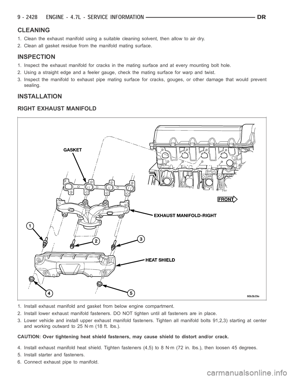
RIGHT EXHAUST MANIFOLD
1. Install exhaust manifold and gasket from below engine compartment.
2. Install lower exhaust manifold fasteners. DO NOT tighten until all fastenersareinplace.
3. Lower vehicle and install upper exhaust manifold fasteners. Tighten all manifold bolts 91,2,3) starting at center
and working outward to 25 Nꞏm (18 ft. lbs.).
CAUTION: Over tightening heat shield fasteners, may cause shield to distort and/or crack.
4. Install exhaust manifold heat shield. Tighten fasteners (4,5) to 8 Nꞏm (72 in. lbs.), then loosen 45 degrees.
5. Install starter and fasteners.
6. Connect exhaust pipe to manifold.
Page 1753 of 5267
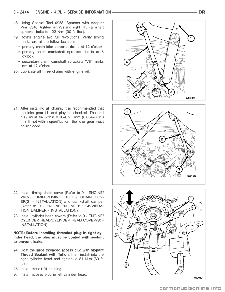
18. Using Special Tool 6958, Spanner with Adaptor
Pins 8346, tighten left (3) and right (4), camshaft
sprocket bolts to 122 Nꞏm (90 ft. lbs.).
19. Rotate engine two full revolutions. Verify timing
marks are at the follow locations:
primary chain idler sprocket dot is at 12 o’clock
primary chain crankshaft sprocket dot is at 6
o’clock
secondary chain camshaft sprockets “V8” marks
are at 12 o’clock
20. Lubricate all three chains with engine oil.
21. After installing all chains, it is recommended that
the idler gear (1) end play be checked. The end
play must be within 0.10–0.25 mm (0.004–0.010
in.). If not within specification, the idler gear must
be replaced.
22. Install timing chain cover (Refer to 9 - ENGINE/
VALVE TIMING/TIMING BELT / CHAIN COV-
ER(S) - INSTALLATION) and crankshaft damper
(Refer to 9 - ENGINE/ENGINE BLOCK/VIBRA-
TION DAMPER - INSTALLATION).
23. Install cylinder head covers (Refer to 9 - ENGINE/
CYLINDER HEAD/CYLINDER HEAD COVER(S) -
INSTALLATION).
NOTE: Before installing threaded plug in right cyl-
inder head, the plug mustbecoatedwithsealant
to prevent leaks.
24. Coat the large threaded access plug withMopar
Thread Sealant with Teflon, then install into the
right cylinder head and tighten to 81 Nꞏm (60 ft.
lbs.).
25. Install the oil fill housing.
26. Install access plug in left cylinder head.
Page 1757 of 5267
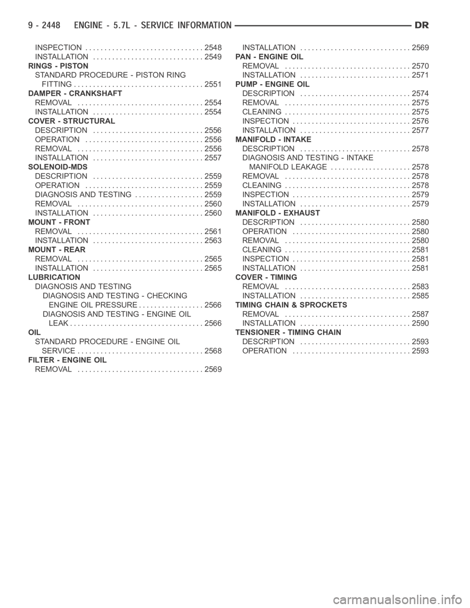
INSPECTION ............................... 2548
INSTALLATION ............................. 2549
RINGS - PISTON
STANDARD PROCEDURE - PISTON RING
FITTING .................................. 2551
DAMPER - CRANKSHAFT
REMOVAL ................................. 2554
INSTALLATION ............................. 2554
COVER - STRUCTURAL
DESCRIPTION ............................. 2556
OPERATION ............................... 2556
REMOVAL ................................. 2556
INSTALLATION ............................. 2557
SOLENOID-MDS
DESCRIPTION ............................. 2559
OPERATION ............................... 2559
DIAGNOSIS AND TESTING .................. 2559
REMOVAL ................................. 2560
INSTALLATION ............................. 2560
MOUNT - FRONT
REMOVAL ................................. 2561
INSTALLATION ............................. 2563
MOUNT - REAR
REMOVAL ................................. 2565
INSTALLATION ............................. 2565
LUBRICATION
DIAGNOSIS AND TESTING
DIAGNOSIS AND TESTING - CHECKING
ENGINE OIL PRESSURE.................. 2566
DIAGNOSIS AND TESTING - ENGINE OIL
LEAK.................................... 2566
OIL
STANDARD PROCEDURE - ENGINE OIL
SERVICE ................................. 2568
FILTER - ENGINE OIL
REMOVAL ................................. 2569INSTALLATION ............................. 2569
PA N - E N G I N E O I L
REMOVAL ................................. 2570
INSTALLATION ............................. 2571
PUMP - ENGINE OIL
DESCRIPTION ............................. 2574
REMOVAL ................................. 2575
CLEANING ................................. 2575
INSPECTION............................... 2576
INSTALLATION ............................. 2577
MANIFOLD - INTAKE
DESCRIPTION ............................. 2578
DIAGNOSIS AND TESTING - INTAKE
MANIFOLD LEAKAGE ..................... 2578
REMOVAL ................................. 2578
CLEANING ................................. 2578
INSPECTION............................... 2579
INSTALLATION ............................. 2579
MANIFOLD - EXHAUST
DESCRIPTION ............................. 2580
OPERATION ............................... 2580
REMOVAL ................................. 2580
CLEANING ................................. 2581
INSPECTION............................... 2581
INSTALLATION ............................. 2581
COVER - TIMING
REMOVAL ................................. 2583
INSTALLATION ............................. 2585
TIMING CHAIN & SPROCKETS
REMOVAL ................................. 2587
INSTALLATION ............................. 2590
TENSIONER - TIMING CHAIN
DESCRIPTION ............................. 2593
OPERATION ............................... 2593
Page 1760 of 5267
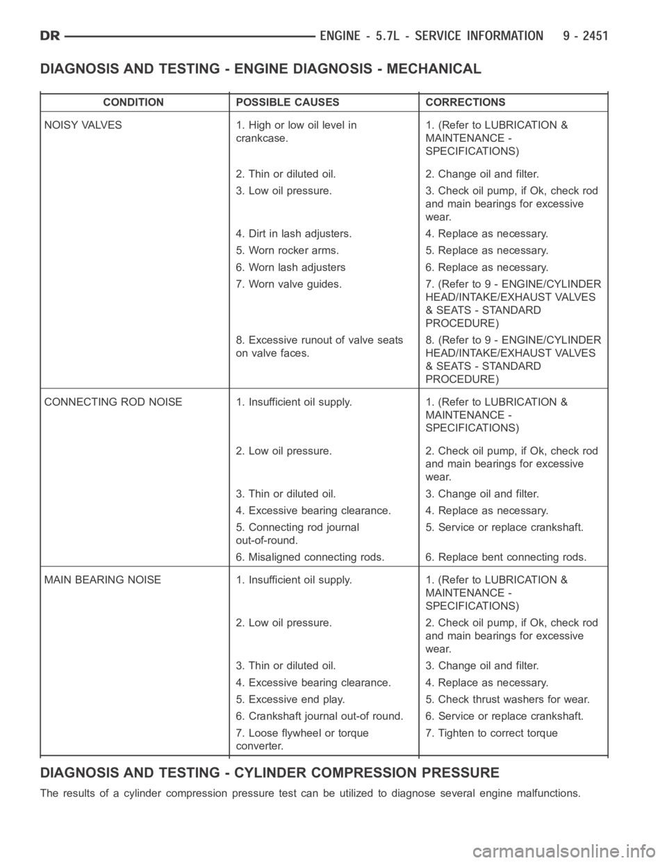
DIAGNOSIS AND TESTING - ENGINE DIAGNOSIS - MECHANICAL
CONDITION POSSIBLE CAUSES CORRECTIONS
NOISY VALVES 1. High or low oil level in
crankcase.1. (Refer to LUBRICATION &
MAINTENANCE -
SPECIFICATIONS)
2. Thin or diluted oil. 2. Change oil and filter.
3. Low oil pressure. 3. Check oil pump, if Ok, check rod
and main bearings for excessive
wear.
4. Dirt in lash adjusters. 4. Replace as necessary.
5. Worn rocker arms. 5. Replace as necessary.
6. Worn lash adjusters 6. Replace as necessary.
7. Worn valve guides. 7. (Refer to 9 - ENGINE/CYLINDER
HEAD/INTAKE/EXHAUST VALVES
& SEATS - STANDARD
PROCEDURE)
8. Excessive runout of valve seats
on valve faces.8. (Refer to 9 - ENGINE/CYLINDER
HEAD/INTAKE/EXHAUST VALVES
& SEATS - STANDARD
PROCEDURE)
CONNECTING ROD NOISE 1. Insufficient oil supply. 1. (Refer to LUBRICATION&
MAINTENANCE -
SPECIFICATIONS)
2. Low oil pressure. 2. Check oil pump, if Ok, check rod
and main bearings for excessive
wear.
3. Thin or diluted oil. 3. Change oil and filter.
4. Excessive bearing clearance. 4. Replace as necessary.
5. Connecting rod journal
out-of-round.5. Service or replace crankshaft.
6. Misaligned connecting rods. 6. Replace bent connecting rods.
MAIN BEARING NOISE 1. Insufficient oil supply. 1. (Refer to LUBRICATION &
MAINTENANCE -
SPECIFICATIONS)
2. Low oil pressure. 2. Check oil pump, if Ok, check rod
and main bearings for excessive
wear.
3. Thin or diluted oil. 3. Change oil and filter.
4. Excessive bearing clearance. 4. Replace as necessary.
5. Excessive end play. 5. Check thrust washers for wear.
6. Crankshaft journal out-of round. 6. Service or replace crankshaft.
7. Loose flywheel or torque
converter.7. Tighten to correct torque
DIAGNOSIS AND TESTING - CYLINDER COMPRESSION PRESSURE
The results of a cylinder compressionpressure test can be utilized to diagnose several engine malfunctions.
Page 1761 of 5267
Ensurethebatteryiscompletelychargedandtheenginestartermotorisingood operating condition. Otherwise the
indicated compression pressures may not be valid for diagnosis purposes.
1. Clean the spark plug recesses with compressed air.
2. Remove the spark plugs.
3. Disable the fuel system (Refer to 14 - FUEL SYSTEM/FUEL DELIVERY - DESCRIPTION).
4. Remove the ASD relay (Refer to 8 - ELECTRICAL/IGNITION CONTROL/AUTO SHUTDOWNRELAY-
REMOVAL).
5. Insert a compression pressure gauge and rotate the engine with the engine starter motor for three revolutions.
6. Record the compression pressure on the 3rd revolution. Continue the test for the remaining cylinders.
7. (Refer to 9 - ENGINE - SPECIFICATIONS) for the correct engine compression pressures.
DIAGNOSIS AND TESTING - CYLINDERCOMBUSTION PRESSURE LEAKAGE
The combustion pressure leakage test provides an accurate means for determining engine condition.
Combustion pressure leakage testing will detect:
Exhaust and intake valve leaks (improper seating).
Leaks between adjacent cylinders or into water jacket.
Any causes for combustion/compression pressure loss.
1. Check the coolant level and fill as required. DO NOT install the radiatorcap.
2. Start and operate the engine until it attains normal operating temperature, then turn the engine OFF.
3. Remove the spark plugs.
4. Remove the oil filler cap.
5. Remove the air cleaner hose.
6. Calibrate the tester according to the manufacturer’s instructions. The shop air source for testing should maintain
483 kPa (70 psi) minimum, 1,379 kPa (200 psi) maximum and 552 kPa (80 psi) recommended.
7. Perform the test procedures on each cylinder according to the tester manufacturer’s instructions. Set piston of
cylinder to be tested at TDC compression,While testing, listen for pressurized air escaping through the throttle
body, tailpipe and oil filler cap opening. Check for bubbles in the radiator coolant.
All gauge pressure indications should be equal, with no more than 25% leakage.
FOR EXAMPLE:At 552 kPa (80 psi) input pressure, a minimum of 414 kPa (60 psi) should be maintained in the
cylinder.
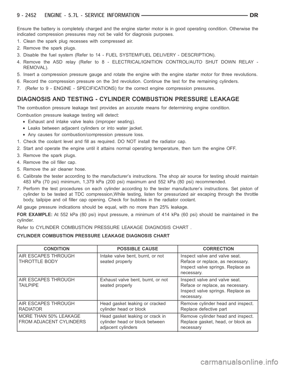
Refer to CYLINDER COMBUSTION PRESSURE LEAKAGE DIAGNOSIS CHART .
CYLINDER COMBUSTION PRESSURE LEAKAGE DIAGNOSIS CHART
CONDITION POSSIBLE CAUSE CORRECTION
AIR ESCAPES THROUGH
THROTTLE BODYIntake valve bent, burnt, or not
seated properlyInspect valve and valve seat.
Reface or replace, as necessary.
Inspect valve springs. Replace as
necessary.
AIR ESCAPES THROUGH
TAILPIPEExhaust valve bent, burnt, or not
seated properlyInspect valve and valve seat.
Reface or replace, as necessary.
Inspect valve springs. Replace as
necessary.
AIR ESCAPES THROUGH
RADIATORHead gasket leaking or cracked
cylinder head or blockRemove cylinder head and inspect.
Replace defective part
MORE THAN 50% LEAKAGE
FROM ADJACENT CYLINDERSHead gasket leaking or crack in
cylinder head or block between
adjacent cylindersRemove cylinder head and inspect.
Replace gasket, head, or block as
necessary
Page 1762 of 5267
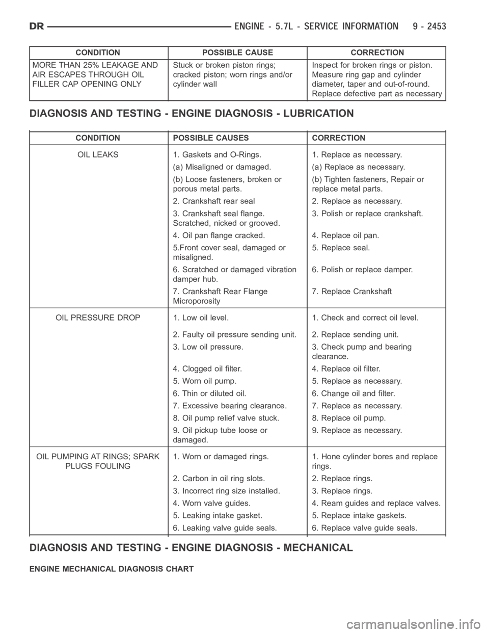
CONDITION POSSIBLE CAUSE CORRECTION
MORE THAN 25% LEAKAGE AND
AIR ESCAPES THROUGH OIL
FILLER CAP OPENING ONLYStuckorbrokenpistonrings;
cracked piston; worn rings and/or
cylinder wallInspect for broken rings or piston.
Measure ring gap and cylinder
diameter, taper and out-of-round.
Replace defective part as necessary
DIAGNOSIS AND TESTING - ENGINE DIAGNOSIS - LUBRICATION
CONDITION POSSIBLE CAUSES CORRECTION
OIL LEAKS 1. Gaskets and O-Rings. 1. Replace as necessary.
(a) Misaligned or damaged. (a) Replace as necessary.
(b) Loose fasteners, broken or
porous metal parts.(b) Tighten fasteners, Repair or
replace metal parts.
2. Crankshaft rear seal 2. Replace as necessary.
3. Crankshaft seal flange.
Scratched, nicked or grooved.3. Polish or replace crankshaft.
4. Oil pan flange cracked. 4. Replace oil pan.
5.Front cover seal, damaged or
misaligned.5. Replace seal.
6. Scratched or damaged vibration
damper hub.6. Polish or replace damper.
7. Crankshaft Rear Flange
Microporosity7. Replace Crankshaft
OIL PRESSURE DROP 1. Low oil level. 1. Check and correct oil level.
2. Faulty oil pressure sending unit. 2. Replace sending unit.
3. Low oil pressure. 3. Check pump and bearing
clearance.
4. Clogged oil filter. 4. Replace oil filter.
5. Worn oil pump. 5. Replace as necessary.
6. Thin or diluted oil. 6. Change oil and filter.
7. Excessive bearing clearance. 7. Replace as necessary.
8. Oil pump relief valve stuck. 8. Replace oil pump.
9. Oil pickup tube loose or
damaged.9. Replace as necessary.
OIL PUMPING AT RINGS; SPARK
PLUGS FOULING1. Worn or damaged rings. 1. Hone cylinder bores and replace
rings.
2. Carbon in oil ring slots. 2. Replace rings.
3. Incorrect ring size installed. 3. Replace rings.
4. Worn valve guides. 4. Ream guides and replace valves.
5. Leaking intake gasket. 5. Replace intake gaskets.
6. Leaking valve guide seals. 6. Replace valve guide seals.
DIAGNOSIS AND TESTING - ENGINE DIAGNOSIS - MECHANICAL
ENGINE MECHANICAL DIAGNOSIS CHART