2006 DODGE RAM SRT-10 check engine
[x] Cancel search: check enginePage 1621 of 5267
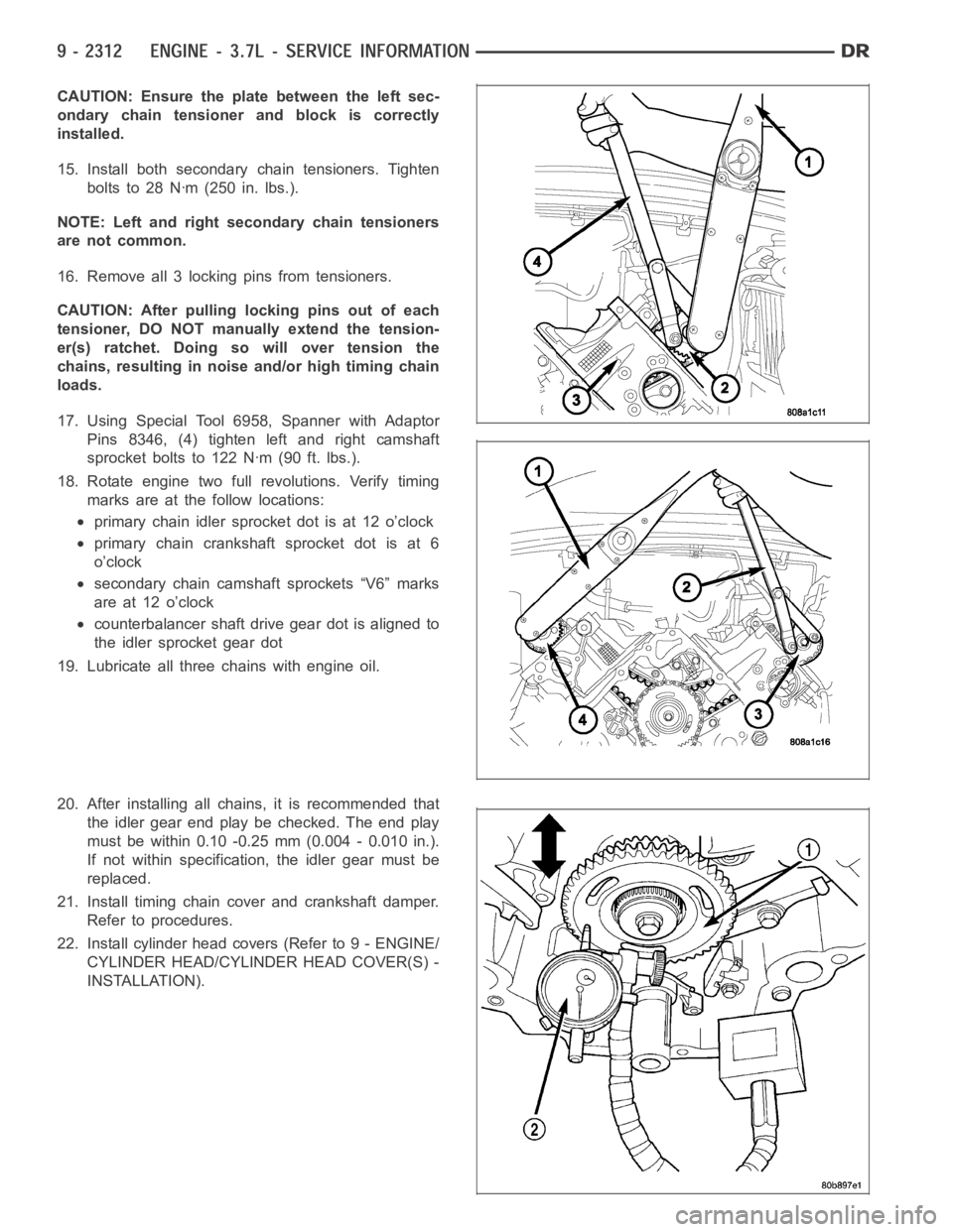
CAUTION: Ensure the plate between the left sec-
ondary chain tensioner and block is correctly
installed.
15. Install both secondary chain tensioners. Tighten
boltsto28Nꞏm(250in.lbs.).
NOTE: Left and right secondary chain tensioners
are not common.
16. Remove all 3 locking pins from tensioners.
CAUTION: After pulling locking pins out of each
tensioner, DO NOT manually extend the tension-
er(s) ratchet. Doing so will over tension the
chains, resulting in noise and/or high timing chain
loads.
17. Using Special Tool 6958, Spanner with Adaptor
Pins 8346, (4) tighten left and right camshaft
sprocket bolts to 122 Nꞏm (90 ft. lbs.).
18. Rotate engine two full revolutions. Verify timing
marks are at the follow locations:
primary chain idler sprocket dot is at 12 o’clock
primary chain crankshaft sprocket dot is at 6
o’clock
secondary chain camshaft sprockets “V6” marks
are at 12 o’clock
counterbalancer shaft drive gear dot is aligned to
the idler sprocket gear dot
19. Lubricate all three chains with engine oil.
20. After installing all chains, it is recommended that
the idler gear end play be checked. The end play
must be within 0.10 -0.25 mm (0.004 - 0.010 in.).
If not within specification, the idler gear must be
replaced.
21. Install timing chain cover and crankshaft damper.
Refer to procedures.
22. Install cylinder head covers (Refer to 9 - ENGINE/
CYLINDER HEAD/CYLINDER HEAD COVER(S) -
INSTALLATION).
Page 1624 of 5267
INSTALLATION ............................. 2394
FLEX PLATE
REMOVAL ................................. 2395
INSTALLATION ............................. 2395
ROD - PISTON & CONNECTING
DESCRIPTION ............................. 2396
STANDARD PROCEDURE - PISTON FITTING . 2396
REMOVAL ................................. 2397
CLEANING ................................. 2397
INSPECTION ............................... 2398
INSTALLATION ............................. 2398
RINGS - PISTON
STANDARD PROCEDURE - PISTON RING
FITTING .................................. 2400
DAMPER - CRANKSHAFT
REMOVAL ................................. 2403
INSTALLATION ............................. 2404
COVER - STRUCTURAL
DESCRIPTION ............................. 2405
OPERATION ............................... 2405
REMOVAL ................................. 2405
INSTALLATION ............................. 2405
MOUNT - FRONT
REMOVAL ................................. 2406
INSTALLATION ............................. 2408
MOUNT - REAR
REMOVAL ................................. 2410
INSTALLATION ............................. 2410
LUBRICATION
DESCRIPTION .............................. 2411
OPERATION ................................ 2411
DIAGNOSIS AND TESTING
DIAGNOSIS AND TESTING - CHECKING
ENGINE OIL PRESSURE.................. 2412
DIAGNOSIS AND TESTING - ENGINE OIL
LEAK.................................... 2413
OIL
STANDARD PROCEDURE - ENGINE OIL
SERVICE ................................. 2414
FILTER - ENGINE OIL
REMOVAL ................................. 2416
INSTALLATION ............................. 2416
PAN - ENGINE OIL
REMOVAL ................................. 2417
INSTALLATION ............................. 2417
SWITCH - OIL PRESSURE
DESCRIPTION
DESCRIPTION ........................... 2418DESCRIPTION ........................... 2418
OPERATION
OPERATION ............................. 2418
OPERATION ............................. 2418
REMOVAL ................................. 2419
INSTALLATION ............................. 2419
PUMP - ENGINE OIL
REMOVAL ................................. 2420
DISASSEMBLY . ............................ 2420
CLEANING ................................. 2420
INSPECTION............................... 2420
ASSEMBLY................................ 2422
INSTALLATION ............................. 2422
MANIFOLD - INTAKE
DESCRIPTION ............................. 2423
DIAGNOSIS AND TESTING - INTAKE
MANIFOLD LEAKAGE ..................... 2423
REMOVAL ................................. 2423
CLEANING ................................. 2424
INSPECTION............................... 2424
INSTALLATION ............................. 2425
MANIFOLD - EXHAUST
DESCRIPTION ............................. 2426
REMOVAL ................................. 2426
CLEANING ................................. 2428
INSPECTION............................... 2428
INSTALLATION ............................. 2428
VALVE TIMING
DESCRIPTION - TIMING DRIVE SYSTEM ..... 2430
OPERATION - TIMING DRIVE SYSTEM....... 2430
STANDARD PROCEDURE
STANDARD PROCEDURE - MEASURING
TIMING CHAIN WEAR..................... 2431
STANDARD PROCEDURE - ENGINE TIMING
- VERIFICATION.......................... 2431
COVER - TIMING
REMOVAL ................................. 2436
INSTALLATION ............................. 2437
TIMING CHAIN & SPROCKETS
REMOVAL ................................. 2438
INSPECTION............................... 2441
INSTALLATION ............................. 2442
SHAFT - IDLER
REMOVAL ................................. 2446
INSTALLATION ............................. 2446
Page 1627 of 5267
DIAGNOSIS AND TESTING - ENGINE DIAGNOSIS - MECHANICAL
CONDITION POSSIBLE CAUSES CORRECTIONS
NOISY VALVES 1. High or low oil level in
crankcase.1. (Refer to LUBRICATION &
MAINTENANCE -
SPECIFICATIONS)
2. Thin or diluted oil. 2. Change oil and filter.
3. Low oil pressure. 3. Check oil pump, if Ok, check rod
and main bearings for excessive
wear.
4. Dirt in lash adjusters. 4. Replace as necessary.
5. Worn rocker arms. 5. Replace as necessary.
6. Worn lash adjusters 6. Replace as necessary.
7. Worn valve guides. 7. (Refer to 9 - ENGINE/CYLINDER
HEAD/INTAKE/EXHAUST VALVES
& SEATS - STANDARD
PROCEDURE)
8. Excessive runout of valve seats
on valve faces.8. (Refer to 9 - ENGINE/CYLINDER
HEAD/INTAKE/EXHAUST VALVES
& SEATS - STANDARD
PROCEDURE)
CONNECTING ROD NOISE 1. Insufficient oil supply. 1. (Refer to LUBRICATION&
MAINTENANCE -
SPECIFICATIONS)
2. Low oil pressure. 2. Check oil pump, if Ok, check rod
and main bearings for excessive
wear.
3. Thin or diluted oil. 3. Change oil and filter.
4. Excessive bearing clearance. 4. Replace as necessary.
5. Connecting rod journal
out-of-round.5. Service or replace crankshaft.
6. Misaligned connecting rods. 6. Replace bent connecting rods.
MAIN BEARING NOISE 1. Insufficient oil supply. 1. (Refer to LUBRICATION &
MAINTENANCE -
SPECIFICATIONS)
2. Low oil pressure. 2. Check oil pump, if Ok, check rod
and main bearings for excessive
wear.
3. Thin or diluted oil. 3. Change oil and filter.
4. Excessive bearing clearance. 4. Replace as necessary.
5. Excessive end play. 5. Check thrust washers for wear.
6. Crankshaft journal out-of round. 6. Service or replace crankshaft.
7. Loose flywheel or torque
converter.7. Tighten to correct torque
DIAGNOSIS AND TESTING - CYLINDER COMPRESSION PRESSURE
The results of a cylinder compressionpressure test can be utilized to diagnose several engine malfunctions.
Page 1628 of 5267
Ensurethebatteryiscompletelychargedandtheenginestartermotorisingood operating condition. Otherwise the
indicated compression pressures may not be valid for diagnosis purposes.
1. Clean the spark plug recesses with compressed air.
2. Remove the spark plugs.
3. Disable the fuel system (Refer to 14 - FUEL SYSTEM/FUEL DELIVERY - DESCRIPTION).
4. Remove the ASD relay (Refer to 8 - ELECTRICAL/IGNITION CONTROL/AUTO SHUTDOWNRELAY-
REMOVAL).
5. Insert a compression pressure gauge and rotate the engine with the engine starter motor for three revolutions.
6. Record the compression pressure on the 3rd revolution. Continue the test for the remaining cylinders.
7. (Refer to 9 - ENGINE - SPECIFICATIONS) for the correct engine compression pressures.
DIAGNOSIS AND TESTING - CYLINDERCOMBUSTION PRESSURE LEAKAGE
The combustion pressure leakage test provides an accurate means for determining engine condition.
Combustion pressure leakage testing will detect:
Exhaust and intake valve leaks (improper seating).
Leaks between adjacent cylinders or into water jacket.
Any causes for combustion/compression pressure loss.
1. Check the coolant level and fill as required. DO NOT install the radiatorcap.
2. Start and operate the engine until it attains normal operating temperature, then turn the engine OFF.
3. Remove the spark plugs.
4. Remove the oil filler cap.
5. Remove the air cleaner hose.
6. Calibrate the tester according to the manufacturer’s instructions. The shop air source for testing should maintain
483 kPa (70 psi) minimum, 1,379 kPa (200 psi) maximum and 552 kPa (80 psi) recommended.
7. Perform the test procedures on each cylinder according to the tester manufacturer’s instructions. Set piston of
cylinder to be tested at TDC compression,While testing, listen for pressurized air escaping through the throttle
body, tailpipe and oil filler cap opening. Check for bubbles in the radiator coolant.
All gauge pressure indications should be equal, with no more than 25% leakage.
FOR EXAMPLE:At 552 kPa (80 psi) input pressure, a minimum of 414 kPa (60 psi) should be maintained in the
cylinder.
Refer to CYLINDER COMBUSTION PRESSURE LEAKAGE DIAGNOSIS CHART .
CYLINDER COMBUSTION PRESSURE LEAKAGE DIAGNOSIS CHART
CONDITION POSSIBLE CAUSE CORRECTION
AIR ESCAPES THROUGH
THROTTLE BODYIntake valve bent, burnt, or not
seated properlyInspect valve and valve seat.
Reface or replace, as necessary.
Inspect valve springs. Replace as
necessary.
AIR ESCAPES THROUGH
TAILPIPEExhaust valve bent, burnt, or not
seated properlyInspect valve and valve seat.
Reface or replace, as necessary.
Inspect valve springs. Replace as
necessary.
AIR ESCAPES THROUGH
RADIATORHead gasket leaking or cracked
cylinder head or blockRemove cylinder head and inspect.
Replace defective part
MORE THAN 50% LEAKAGE
FROM ADJACENT CYLINDERSHead gasket leaking or crack in
cylinder head or block between
adjacent cylindersRemove cylinder head and inspect.
Replace gasket, head, or block as
necessary
Page 1640 of 5267
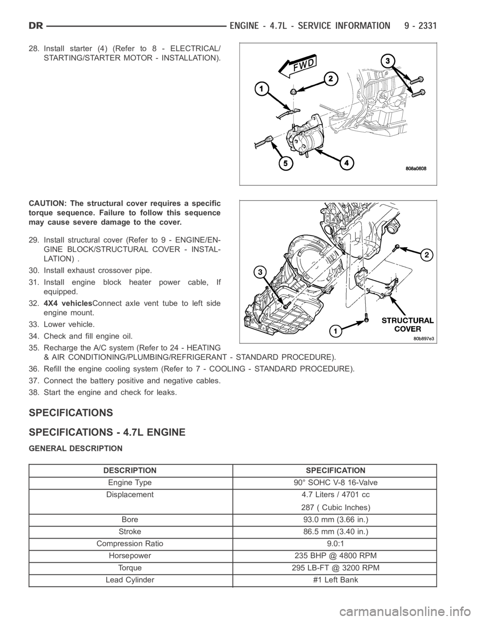
28. Install starter (4) (Refer to 8 - ELECTRICAL/
STARTING/STARTER MOTOR - INSTALLATION).
CAUTION: The structural cover requires a specific
torque sequence. Failure to follow this sequence
may cause severe damage to the cover.
29. Install structural cover (Refer to 9 - ENGINE/EN-
GINE BLOCK/STRUCTURAL COVER - INSTAL-
LATION) .
30. Install exhaust crossover pipe.
31. Install engine block heater power cable, If
equipped.
32.4X4 vehiclesConnect axle vent tube to left side
engine mount.
33. Lower vehicle.
34. Check and fill engine oil.
35. Recharge the A/C system (Refer to 24 - HEATING
& AIR CONDITIONING/PLUMBING/REFRIGERANT - STANDARD PROCEDURE).
36. Refill the engine cooling system (Refer to 7 - COOLING - STANDARD PROCEDURE).
37. Connect the battery positive and negative cables.
38. Start the engine and check for leaks.
SPECIFICATIONS
SPECIFICATIONS - 4.7L ENGINE
GENERAL DESCRIPTION
DESCRIPTION SPECIFICATION
Engine Type 90° SOHC V-8 16-Valve
Displacement 4.7 Liters / 4701 cc
287 ( Cubic Inches)
Bore 93.0 mm (3.66 in.)
Stroke 86.5 mm (3.40 in.)
Compression Ratio 9.0:1
Horsepower 235 BHP @ 4800 RPM
Torque 295 LB-FT @ 3200 RPM
Lead Cylinder #1 Left Bank
Page 1654 of 5267
Install Cooling System Tester Special Tool # 7700 or equivalent to pressure cap neck. Start the engine and observe
the tester’s pressure gauge. If gauge pulsates with every power stroke of acylinder a combustion pressure leak is
evident.
CHEMICAL TEST METHOD
Combustion leaks into the cooling system can also be checked by using Bloc-Chek Kit Special Tool # C-3685-A or
equivalent. Perform test following the procedures supplied with the toolkit.
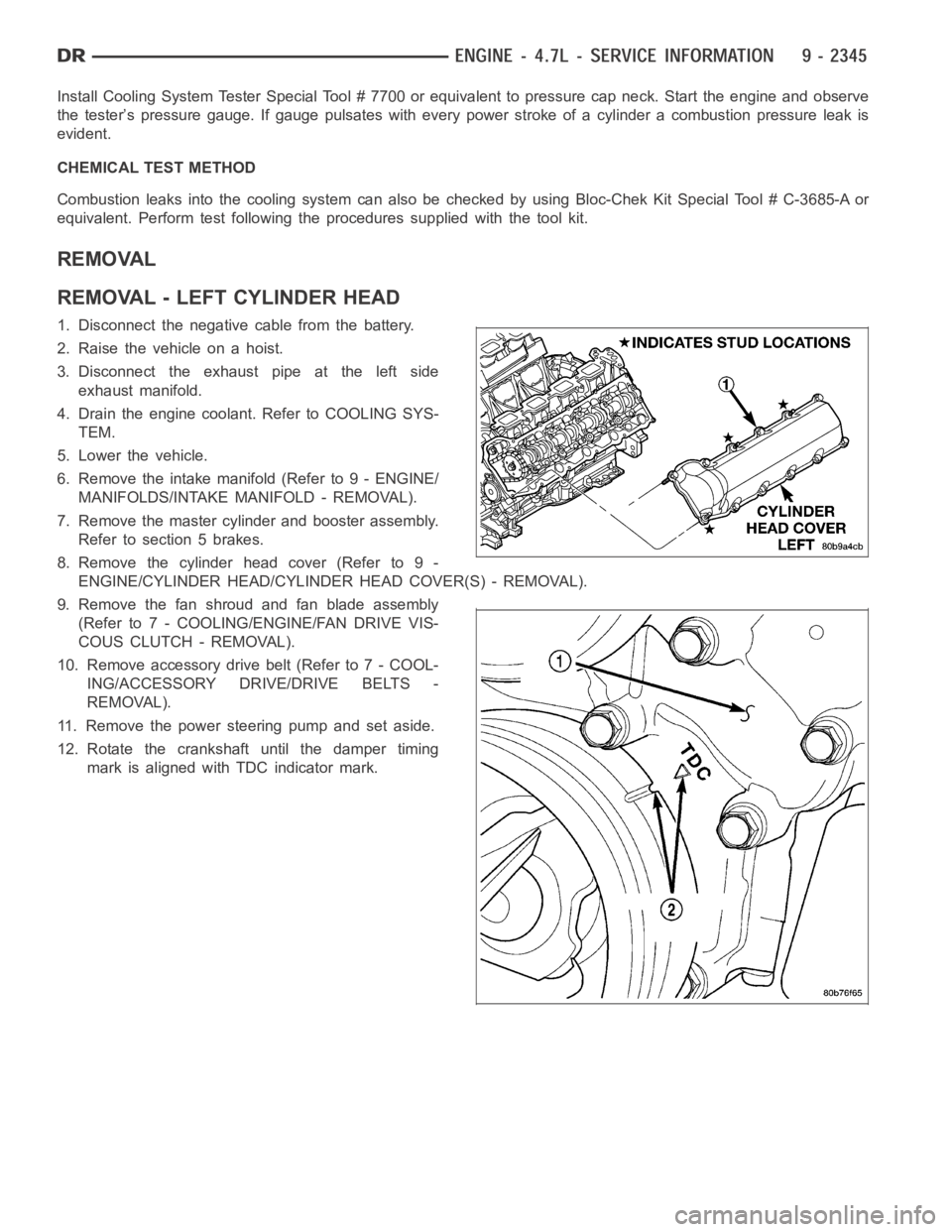
REMOVAL
REMOVAL - LEFT CYLINDER HEAD
1. Disconnect the negative cable from the battery.
2. Raise the vehicle on a hoist.
3. Disconnect the exhaust pipe at the left side
exhaust manifold.
4. Drain the engine coolant. Refer to COOLING SYS-
TEM.
5. Lower the vehicle.
6. Remove the intake manifold (Refer to 9 - ENGINE/
MANIFOLDS/INTAKE MANIFOLD - REMOVAL).
7. Remove the master cylinder and booster assembly.
Refer to section 5 brakes.
8. Remove the cylinder head cover (Refer to 9 -
ENGINE/CYLINDER HEAD/CYLINDER HEAD COVER(S) - REMOVAL).
9. Remove the fan shroud and fan blade assembly
(Refer to 7 - COOLING/ENGINE/FAN DRIVE VIS-
COUS CLUTCH - REMOVAL).
10. Remove accessory drive belt (Refer to 7 - COOL-
ING/ACCESSORY DRIVE/DRIVE BELTS -
REMOVAL).
11. Remove the power steering pump and set aside.
12. Rotate the crankshaft until the damper timing
mark is aligned with TDC indicator mark.
Page 1662 of 5267
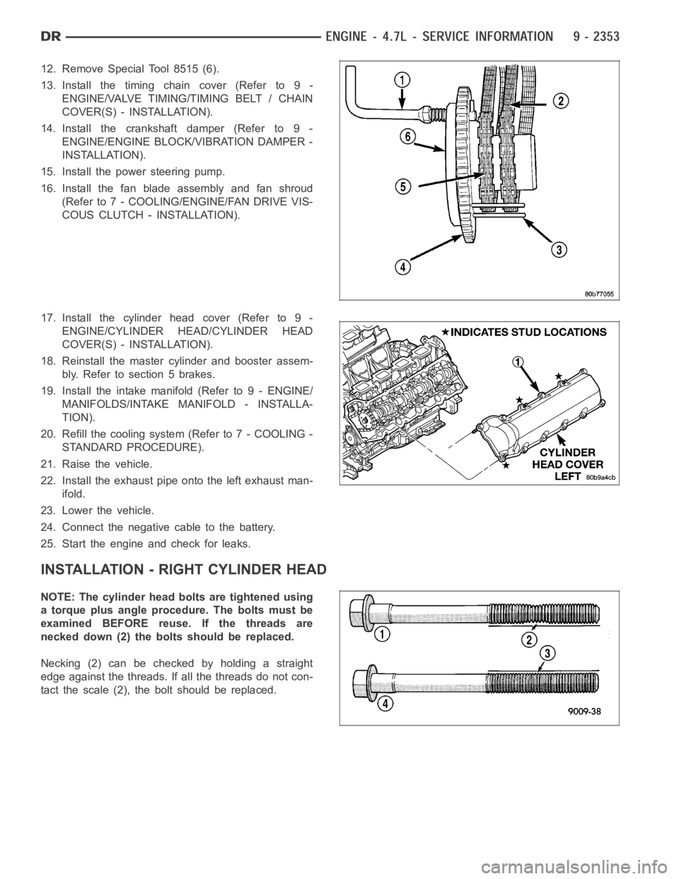
12. Remove Special Tool 8515 (6).
13. Install the timing chain cover (Refer to 9 -
ENGINE/VALVE TIMING/TIMING BELT / CHAIN
COVER(S) - INSTALLATION).
14. Install the crankshaft damper (Refer to 9 -
ENGINE/ENGINE BLOCK/VIBRATION DAMPER -
INSTALLATION).
15. Install the power steering pump.
16. Install the fan blade assembly and fan shroud
(Refer to 7 - COOLING/ENGINE/FAN DRIVE VIS-
COUS CLUTCH - INSTALLATION).
17. Install the cylinder head cover (Refer to 9 -
ENGINE/CYLINDER HEAD/CYLINDER HEAD
COVER(S) - INSTALLATION).
18. Reinstall the master cylinder and booster assem-
bly.Refertosection5brakes.
19. Install the intake manifold (Refer to 9 - ENGINE/
MANIFOLDS/INTAKE MANIFOLD - INSTALLA-
TION).
20. Refill the cooling system (Refer to 7 - COOLING -
STANDARD PROCEDURE).
21. Raise the vehicle.
22. Install the exhaust pipe onto the left exhaust man-
ifold.
23. Lower the vehicle.
24. Connect the negative cable to the battery.
25. Start the engine and check for leaks.
INSTALLATION - RIGHT CYLINDER HEAD
NOTE: The cylinder head bolts are tightened using
a torque plus angle procedure. The bolts must be
examined BEFORE reuse. If the threads are
necked down (2) the bolts should be replaced.
Necking(2)canbecheckedbyholdingastraight
edge against the threads. If all the threads do not con-
tactthescale(2),theboltshouldbereplaced.
Page 1665 of 5267
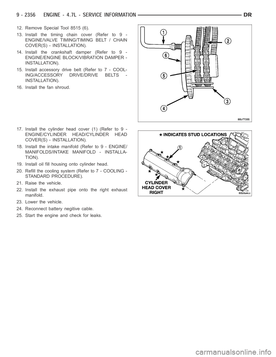
12. Remove Special Tool 8515 (6).
13. Install the timing chain cover (Refer to 9 -
ENGINE/VALVE TIMING/TIMING BELT / CHAIN
COVER(S) - INSTALLATION).
14. Install the crankshaft damper (Refer to 9 -
ENGINE/ENGINE BLOCK/VIBRATION DAMPER -
INSTALLATION).
15. Install accessory drive belt (Refer to 7 - COOL-
ING/ACCESSORY DRIVE/DRIVE BELTS -
INSTALLATION).
16. Install the fan shroud.
17. Install the cylinder head cover (1) (Refer to 9 -
ENGINE/CYLINDER HEAD/CYLINDER HEAD
COVER(S) - INSTALLATION).
18. Install the intake manifold (Refer to 9 - ENGINE/
MANIFOLDS/INTAKE MANIFOLD - INSTALLA-
TION).
19. Install oil fill housing onto cylinder head.
20. Refill the cooling system (Refer to 7 - COOLING -
STANDARD PROCEDURE).
21. Raise the vehicle.
22. Install the exhaust pipe onto the right exhaust
manifold.
23. Lower the vehicle.
24. Reconnect battery negitive cable.
25. Start the engine and check for leaks.