2006 DODGE RAM SRT-10 check engine
[x] Cancel search: check enginePage 1477 of 5267
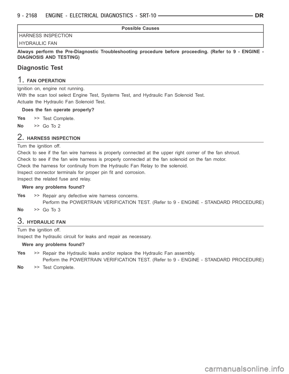
Possible Causes
HARNESS INSPECTION
HYDRAULIC FAN
Always perform the Pre-Diagnostic Troubleshooting procedure before proceeding. (Refer to 9 - ENGINE -
DIAGNOSIS AND TESTING)
Diagnostic Test
1.FAN OPERATION
Ignition on, engine not running.
With the scan tool select Engine Test, Systems Test, and Hydraulic Fan Solenoid Test.
Actuate the Hydraulic Fan Solenoid Test.
Does the fan operate properly?
Ye s>>
Te s t C o m p l e t e .
No>>
Go To 2
2.HARNESS INSPECTION
Turn the ignition off.
Check to see if the fan wire harness is properly connected at the upper rightcorner of the fan shroud.
Check to see if the fan wire harness is properly connected at the fan solenoidonthefanmotor.
Check the harness for continuity from the Hydraulic Fan Relay to the solenoid.
Inspect connector terminals for proper pin fit and corrosion.
Inspect the related fuse and relay.
Were any problems found?
Ye s>>
Repair any defective wire harness concerns.
Perform the POWERTRAIN VERIFICATION TEST. (Refer to 9 - ENGINE - STANDARD PROCEDURE)
No>>
Go To 3
3.HYDRAULIC FAN
Turn the ignition off.
Inspect the hydraulic circuit for leaks and repair as necessary.
Were any problems found?
Ye s>>
Repair the Hydraulic leaks and/or replace the Hydraulic Fan assembly.
Perform the POWERTRAIN VERIFICATION TEST. (Refer to 9 - ENGINE - STANDARD PROCEDURE)
No>>
Te s t C o m p l e t e .
Page 1484 of 5267
23. If thelift foot setsare continually used, a speed control overshoot/undershoot condition will develop.
24. To
unlearnthe overshoot/undershoot condition, the vehicle operator has to press and release the set button
while maintaining the desired set speedusing the accelerator pedal (not decelerating or accelerating).
25. Then turn the cruise control switch to the OFF position (or press the CANCEL button if equipped) after waiting
10 seconds.
26. This procedure must be performed approximately 10-15 times to completely unlearn the overshoot/undershoot
condition.
Did the Speed Control pass the above test?
Ye s>>
Repair is complete.
No>>
Check for any related Technical Service Bulletins and/or refer to the appropriate Diagnostic Procedure.
3.POWERTRAIN VERIFICATION TEST 2
1. If this vehicle is equipped with an Electronic Throttle Control system,and the APP Sensors, PCM, or Throttle
Body Assembly has been replaced use a scan tool to perform the ETC RELEARN function.
NOTE: 2. After completing the Powertrain Verification Test the Transmission Verification Test must be per-
formed.
NOTE: 3. If the PCM has been replaced and the correct VIN and mileage have notbeen programmed, a DTC
will set in the ABS Module, Airbag Module and the SKIM/SKREEM.
NOTE: 4. If the vehicle is equipped with a Sentry Key Remote Entry, Secret Key data must be updated. Refer
to the Service Information for the PCM, SKIM/SKREEM and the Transponder (ignition key) for programming
information. Using the scan tool, program the Secret Key information intothe PCM using the PCM replaced
function under the WCM menu.
5. Inspect the vehicle to make sure that all components related to the repair are properly installed and connected.
6. With the scan tool, clear DTCs.
7. Perform generator output test. Refer to the appropriate service information as necessary.
8. Start the engine and set engine speed to 2000 RPM for at least thirty seconds.
9. Cycle the ignition key off and on.
10. With the scan tool, read the DTCs.
Are any DTCs or symptoms remaining?
Ye s>>
Check for any Technical Service Bulletins and/or refer to the appropriateDiagnostic Procedure.
No>>
Repair is complete.
4.POWERTRAIN VERIFICATION TEST 3
1. Install the Miller Tool #8404 Evaporative Emission Leak Detector (EELD) according to the instructions in the pre-
vious DTC table.
2. Set the smoke/air control switch to AIR.
3. Insert the tester’s AIR supply tip (clear hose) into the appropriate calibration orifice on the tester’s control panel
(based on DTC leak size).
4. Press the remote smoke/air start button.
5. Position the red flag on the air flow meter so it is aligned with the indicator ball.
6. When the calibration is complete, release the remote button. The EELD flow meter is now calibrated in liters per
minute to the size of leak indicated by the DTC set in the PCM.
7. Install the service port adapter #8404-14 on the vehicle’s service port.
8. Connect the Air supply hose from the EELD to the vehicle.
9. Press the remote button to activate AIR flow.
NOTE: 10. Larger volume fuel tanks, lower fuel levels or if the vehicle is equipped with a Flow Management
Valve may indicate high flow and will require 4 to 5 minutes to fill.
11. Compare the flow meter indicator ball reading to the red flag.
12. ABOVE the red flag indicates a leak present.
13. BELOW the red flag indicates a sealed system.
Page 1485 of 5267
NOTE: If this vehicle is equipped with an Electronic Throttle Control system, and the APP Sensors, PCM, or
Throttle Body Assembly have been replaced, use the scan tool to perform theETC RELEARN function.
14. If the indicator ball shows a leak present, perform the smoke test indicated in the previous test and identify the
leak and repair. Perform this verification test when the repair is complete.
Didtheindicatorballindicatethealeakispresent?
Ye s>>
Repeat the DTC test to identify the leak and repair.
No>>
Repair is complete.
5.POWERTRAIN VERIFICATION TEST 4
NOTE: 1. After completing the Powertrain Verification Test the Transmission Verification Test must be per-
formed.
NOTE: 2. If the PCM has been replaced and the correct VIN and mileage have notbeen programmed, a DTC
will set in the ABS Module, Airbag Module and the SKIM/SKREEM.
NOTE: 3. If the vehicle is equipped with a Sentry Key Remote Entry, Secret Key data must be updated. Refer
to the Service Information for the PCM, SKIM/SKREEM and the Transponder (ignition key) for programming
information. Using the scan tool, program the Secret Key information intothe PCM using the PCM replaced
function under the WCM menu.
NOTE: 4. If this vehicle is equipped with an Electronic Throttle Control system, and the APP Sensors, PCM,
or Throttle Body Assembly have been replaced, use the scan tool to perform the ETC RELEARN function.
NOTE: 5. When replacing an O2 Sensor, the PCM RAM memory must be cleared, either by disconnecting the
PCM C1 connector or momentarily disconnecting the Battery negative terminal.
6. The NGC learns the characteristics of each O2 heater element and these old values should be cleared when
installing a new O2 sensor. The customermay experience driveability issues if this is not performed.
7. Inspect the vehicle to make sure that all engine components are properlyinstalled and connected. Reassemble
and reconnect components as necessary.
8. Connect the scan tool to the data link connector.
9. Make sure the fuel tank has at least a quarter tank of fuel. Turn off all accessories.
10. If the Catalyst was replaced, with the scan tool go to the MiscellaneousMenu Option
Catalyst Replacedand
press enter.
11. If a Comprehensive Component DTC was repaired, perform steps 12 - 14. Ifa Major OBDII Monitor DTC was
repaired skip those steps and continue verification.
12. After the ignition has been off for at least 10 seconds, restart the vehicle and run 2 minutes.
13. With the scan tool, monitor the appropriate pre-test enabling conditions until all conditions have been met. Once
the conditions have been met, switch screen to the appropriate OBDII monitor, (Audible beeps when the monitor is
running).
14. If the repaired OBDII trouble code has reset or was seen in the monitor while on the road test, the repair is not
complete. Check for any related technical service bulletins or flash updates and return to Engine Electrical Diag-
nostic List.
15. If the conditions cannot be duplicated, erase all DTCs with the Scan tool.
16. If another DTC has set, return to the Engine Electrical Diagnostic Listand follow the path specified for that DTC.
Did the OBDII Monitor run successfully and has the Good Trip Counter changed to one or more?
Ye s>>
Repair is complete.
No>>
Check for any related Technical Service Bulletins and/or refer to the appropriate Diagnostic Procedure.
Page 1488 of 5267
REMOVAL ................................. 2255
INSTALLATION ............................. 2256
PLATE-FLEX
REMOVAL ................................. 2257
INSTALLATION ............................. 2257
ROD-PISTON AND CONNECTING
DESCRIPTION ............................. 2258
STANDARD PROCEDURE
CONNECTING ROD BEARING FITTING .... 2258
STANDARD PROCEDURE - PISTON
FITTING.................................. 2261
REMOVAL ................................. 2262
CLEANING ................................. 2262
INSPECTION ............................... 2262
INSTALLATION ............................. 2263
RINGS-PISTON
STANDARD PROCEDURE - PISTON RING
FITTING .................................. 2265
DAMPER-CRANKSHAFT
REMOVAL ................................. 2268
INSTALLATION ............................. 2269
COVER-STRUCTURAL
DESCRIPTION ............................. 2270
OPERATION ............................... 2270
REMOVAL ................................. 2270
INSTALLATION ............................. 2270
MOUNT-FRONT
REMOVAL ................................. 2271
INSTALLATION ............................. 2273
MOUNT-REAR
REMOVAL ................................. 2275
INSTALLATION ............................. 2275
LUBRICATION
DESCRIPTION ............................. 2276
OPERATION ............................... 2276
DIAGNOSIS AND TESTING
DIAGNOSIS AND TESTING - ENGINE OIL
LEAK.................................... 2278
DIAGNOSIS AND TESTING - CHECKING
ENGINE OIL PRESSURE.................. 2279
DIAGNOSIS AND TESTING - REAR SEAL
AREA LEAKS............................. 2279
PAN-ENGINE OIL
DESCRIPTION ............................. 2280
REMOVAL ................................. 2281
CLEANING ................................. 2282
INSPECTION ............................... 2282
INSTALLATION ............................. 2282SWITCH-OIL PRESSURE
DESCRIPTION ............................. 2284
OPERATION ............................... 2284
REMOVAL ................................. 2284
INSTALLATION ............................. 2284
PUMP-ENGINE OIL
REMOVAL ................................. 2285
DISASSEMBLY . ............................ 2285
INSPECTION............................... 2285
ASSEMBLY................................ 2287
INSTALLATION ............................. 2287
FILTER-ENGINE OIL
REMOVAL ................................. 2288
INSTALLATION ............................. 2288
OIL
STANDARD PROCEDURE - ENGINE OIL
SERVICE ................................. 2289
MANIFOLD-INTAKE
DESCRIPTION ............................. 2291
DIAGNOSIS AND TESTING - INTAKE
MANIFOLD LEAKS ........................ 2291
REMOVAL ................................. 2291
INSTALLATION ............................. 2292
MANIFOLD-EXHAUST
DESCRIPTION ............................. 2294
REMOVAL ................................. 2294
INSTALLATION ............................. 2295
VALVE TIMING
DESCRIPTION ............................. 2297
OPERATION ............................... 2297
STANDARD PROCEDURE
MEASURING TIMING CHAIN WEAR ........ 2298
SERVICE PROCEDURE - TIMING
VERIFICATION........................... 2298
SHAFT-BALANCE
REMOVAL ................................. 2302
INSTALLATION ............................. 2303
SHAFT-IDLER
REMOVAL ................................. 2304
INSTALLATION ............................. 2304
COVER-TIMING
REMOVAL ................................. 2305
INSTALLATION ............................. 2306
CHAIN AND SPROCKETS-TIMING
REMOVAL ................................. 2307
INSPECTION............................... 2309
INSTALLATION ............................. 2310
Page 1492 of 5267
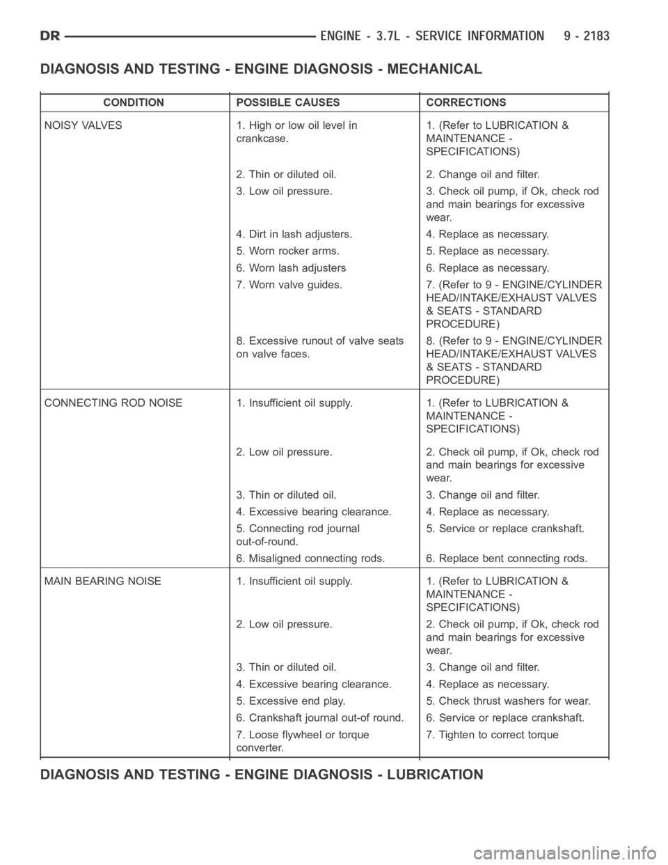
DIAGNOSIS AND TESTING - ENGINE DIAGNOSIS - MECHANICAL
CONDITION POSSIBLE CAUSES CORRECTIONS
NOISY VALVES 1. High or low oil level in
crankcase.1. (Refer to LUBRICATION &
MAINTENANCE -
SPECIFICATIONS)
2. Thin or diluted oil. 2. Change oil and filter.
3. Low oil pressure. 3. Check oil pump, if Ok, check rod
and main bearings for excessive
wear.
4. Dirt in lash adjusters. 4. Replace as necessary.
5. Worn rocker arms. 5. Replace as necessary.
6. Worn lash adjusters 6. Replace as necessary.
7. Worn valve guides. 7. (Refer to 9 - ENGINE/CYLINDER
HEAD/INTAKE/EXHAUST VALVES
& SEATS - STANDARD
PROCEDURE)
8. Excessive runout of valve seats
on valve faces.8. (Refer to 9 - ENGINE/CYLINDER
HEAD/INTAKE/EXHAUST VALVES
& SEATS - STANDARD
PROCEDURE)
CONNECTING ROD NOISE 1. Insufficient oil supply. 1. (Refer to LUBRICATION&
MAINTENANCE -
SPECIFICATIONS)
2. Low oil pressure. 2. Check oil pump, if Ok, check rod
and main bearings for excessive
wear.
3. Thin or diluted oil. 3. Change oil and filter.
4. Excessive bearing clearance. 4. Replace as necessary.
5. Connecting rod journal
out-of-round.5. Service or replace crankshaft.
6. Misaligned connecting rods. 6. Replace bent connecting rods.
MAIN BEARING NOISE 1. Insufficient oil supply. 1. (Refer to LUBRICATION &
MAINTENANCE -
SPECIFICATIONS)
2. Low oil pressure. 2. Check oil pump, if Ok, check rod
and main bearings for excessive
wear.
3. Thin or diluted oil. 3. Change oil and filter.
4. Excessive bearing clearance. 4. Replace as necessary.
5. Excessive end play. 5. Check thrust washers for wear.
6. Crankshaft journal out-of round. 6. Service or replace crankshaft.
7. Loose flywheel or torque
converter.7. Tighten to correct torque
DIAGNOSIS AND TESTING - ENGINE DIAGNOSIS - LUBRICATION
Page 1493 of 5267
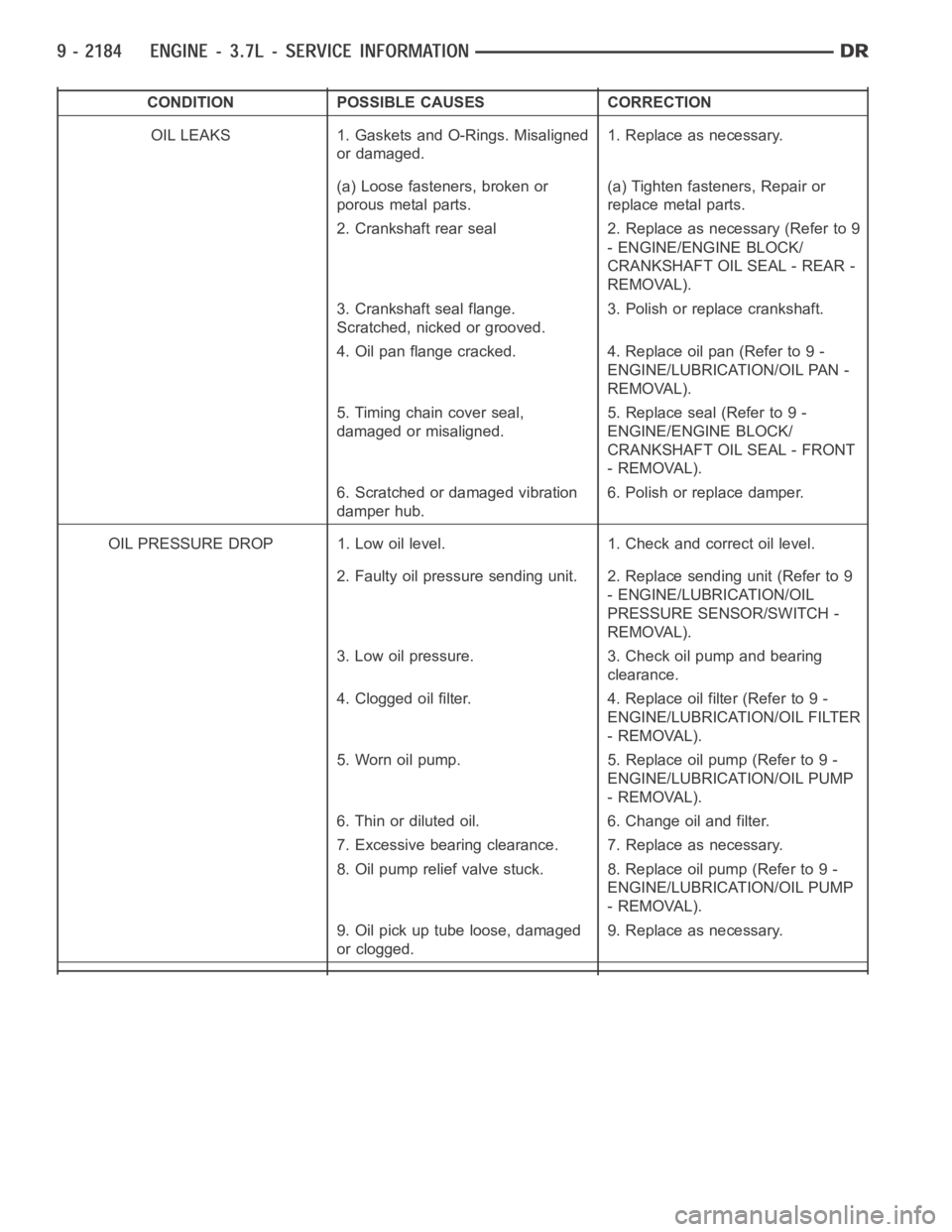
CONDITION POSSIBLE CAUSES CORRECTION
OIL LEAKS 1. Gaskets and O-Rings. Misaligned
or damaged.1. Replace as necessary.
(a) Loose fasteners, broken or
porous metal parts.(a) Tighten fasteners, Repair or
replace metal parts.
2. Crankshaft rear seal 2. Replace as necessary (Refer to 9
- ENGINE/ENGINE BLOCK/
CRANKSHAFT OIL SEAL - REAR -
REMOVAL).
3. Crankshaft seal flange.
Scratched, nicked or grooved.3. Polish or replace crankshaft.
4. Oil pan flange cracked. 4. Replace oil pan (Refer to 9 -
ENGINE/LUBRICATION/OIL PAN -
REMOVAL).
5. Timing chain cover seal,
damaged or misaligned.5. Replace seal (Refer to 9 -
ENGINE/ENGINE BLOCK/
CRANKSHAFT OIL SEAL - FRONT
- REMOVAL).
6. Scratched or damaged vibration
damper hub.6. Polish or replace damper.
OIL PRESSURE DROP 1. Low oil level. 1. Check and correct oil level.
2. Faulty oil pressure sending unit. 2. Replace sending unit (Refer to 9
- ENGINE/LUBRICATION/OIL
PRESSURE SENSOR/SWITCH -
REMOVAL).
3. Low oil pressure. 3. Check oil pump and bearing
clearance.
4. Clogged oil filter. 4. Replace oil filter (Refer to 9 -
ENGINE/LUBRICATION/OIL FILTER
- REMOVAL).
5. Worn oil pump. 5. Replace oil pump (Refer to 9 -
ENGINE/LUBRICATION/OIL PUMP
- REMOVAL).
6. Thin or diluted oil. 6. Change oil and filter.
7. Excessive bearing clearance. 7. Replace as necessary.
8. Oil pump relief valve stuck. 8. Replace oil pump (Refer to 9 -
ENGINE/LUBRICATION/OIL PUMP
- REMOVAL).
9. Oil pick up tube loose, damaged
or clogged.9. Replace as necessary.
Page 1494 of 5267
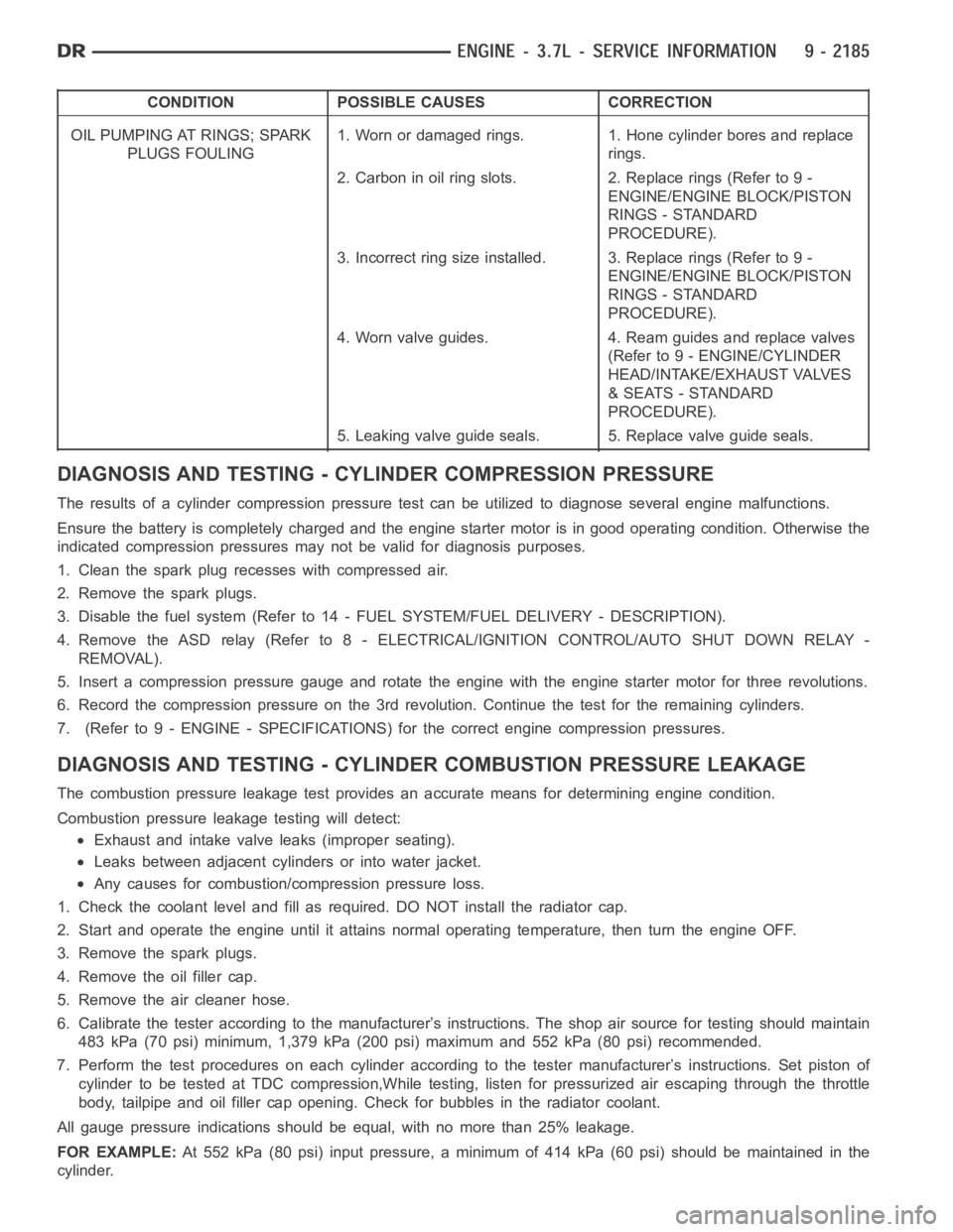
CONDITION POSSIBLE CAUSES CORRECTION
OIL PUMPING AT RINGS; SPARK
PLUGS FOULING1. Worn or damaged rings. 1. Hone cylinder bores and replace
rings.
2. Carbon in oil ring slots. 2. Replace rings (Refer to 9 -
ENGINE/ENGINE BLOCK/PISTON
RINGS - STANDARD
PROCEDURE).
3. Incorrect ring size installed. 3. Replace rings (Refer to 9 -
ENGINE/ENGINE BLOCK/PISTON
RINGS - STANDARD
PROCEDURE).
4. Worn valve guides. 4. Ream guides and replace valves
(Refer to 9 - ENGINE/CYLINDER
HEAD/INTAKE/EXHAUST VALVES
& SEATS - STANDARD
PROCEDURE).
5. Leaking valve guide seals. 5. Replace valve guide seals.
DIAGNOSIS AND TESTING - CYLINDER COMPRESSION PRESSURE
The results of a cylinder compressionpressure test can be utilized to diagnose several engine malfunctions.
Ensurethebatteryiscompletelychargedandtheenginestartermotorisingood operating condition. Otherwise the
indicated compression pressures may not be valid for diagnosis purposes.
1. Clean the spark plug recesses with compressed air.
2. Remove the spark plugs.
3. Disable the fuel system (Refer to 14 - FUEL SYSTEM/FUEL DELIVERY - DESCRIPTION).
4. Remove the ASD relay (Refer to 8 - ELECTRICAL/IGNITION CONTROL/AUTO SHUTDOWNRELAY-
REMOVAL).
5. Insert a compression pressure gauge and rotate the engine with the engine starter motor for three revolutions.
6. Record the compression pressure on the 3rd revolution. Continue the test for the remaining cylinders.
7. (Refer to 9 - ENGINE - SPECIFICATIONS) for the correct engine compression pressures.
DIAGNOSIS AND TESTING - CYLINDERCOMBUSTION PRESSURE LEAKAGE
The combustion pressure leakage test provides an accurate means for determining engine condition.
Combustion pressure leakage testing will detect:
Exhaust and intake valve leaks (improper seating).
Leaks between adjacent cylinders or into water jacket.
Any causes for combustion/compression pressure loss.
1. Check the coolant level and fill as required. DO NOT install the radiatorcap.
2. Start and operate the engine until it attains normal operating temperature, then turn the engine OFF.
3. Remove the spark plugs.
4. Remove the oil filler cap.
5. Remove the air cleaner hose.
6. Calibrate the tester according to the manufacturer’s instructions. The shop air source for testing should maintain
483 kPa (70 psi) minimum, 1,379 kPa (200 psi) maximum and 552 kPa (80 psi) recommended.
7. Perform the test procedures on each cylinder according to the tester manufacturer’s instructions. Set piston of
cylinder to be tested at TDC compression,While testing, listen for pressurized air escaping through the throttle
body, tailpipe and oil filler cap opening. Check for bubbles in the radiator coolant.
All gauge pressure indications should be equal, with no more than 25% leakage.
FOR EXAMPLE:At 552 kPa (80 psi) input pressure, a minimum of 414 kPa (60 psi) should be maintained in the
cylinder.
Page 1498 of 5267
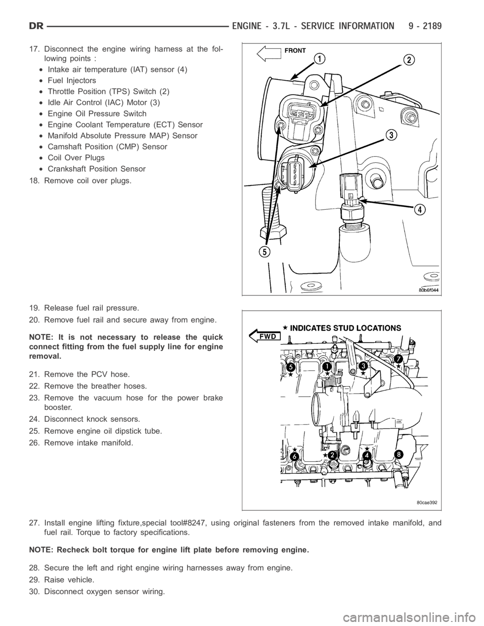
17. Disconnect the engine wiring harness at the fol-
lowing points :
Intake air temperature (IAT) sensor (4)
Fuel Injectors
Throttle Position (TPS) Switch (2)
Idle Air Control (IAC) Motor (3)
Engine Oil Pressure Switch
Engine Coolant Temperature (ECT) Sensor
Manifold Absolute Pressure MAP) Sensor
Camshaft Position (CMP) Sensor
Coil Over Plugs
Crankshaft Position Sensor
18. Remove coil over plugs.
19. Release fuel rail pressure.
20. Remove fuel rail and secure away from engine.
NOTE: It is not necessary to release the quick
connect fitting from the fuel supply line for engine
removal.
21. Remove the PCV hose.
22. Remove the breather hoses.
23. Remove the vacuum hose for the power brake
booster.
24. Disconnect knock sensors.
25. Remove engine oil dipstick tube.
26. Remove intake manifold.
27. Install engine lifting fixture,special tool#8247, using original fasteners from the removed intake manifold, and
fuel rail. Torque to factory specifications.
NOTE: Recheck bolt torque for engine lift plate before removing engine.
28. Secure the left and right engine wiring harnesses away from engine.
29. Raise vehicle.
30. Disconnect oxygen sensor wiring.