2006 DODGE RAM SRT-10 check engine
[x] Cancel search: check enginePage 1504 of 5267
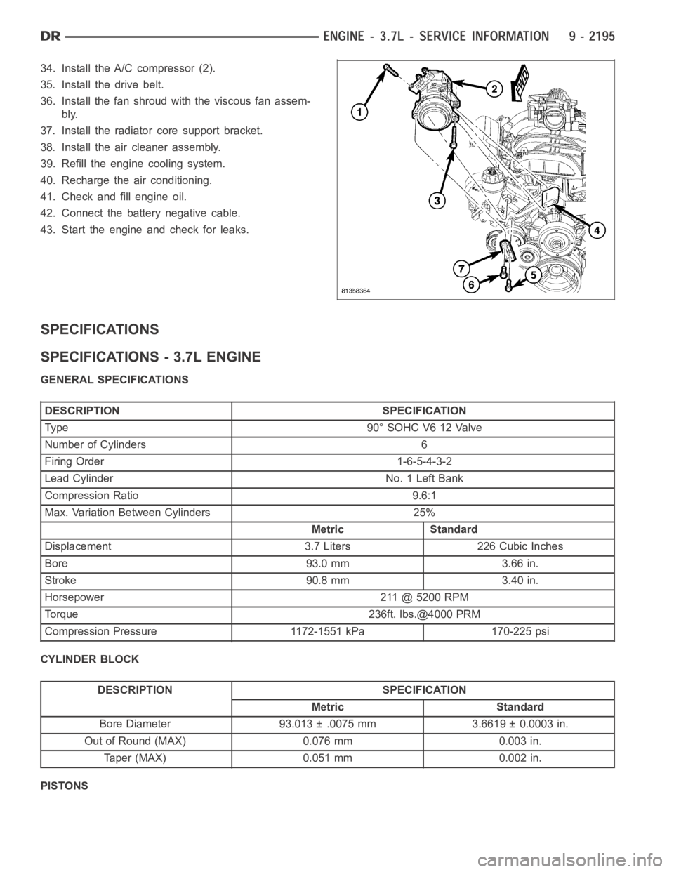
34. Install the A/C compressor (2).
35. Install the drive belt.
36. Install the fan shroud with the viscous fan assem-
bly.
37. Install the radiator core support bracket.
38. Install the air cleaner assembly.
39. Refill the engine cooling system.
40. Recharge the air conditioning.
41. Check and fill engine oil.
42. Connect the battery negative cable.
43. Start the engine and check for leaks.
SPECIFICATIONS
SPECIFICATIONS - 3.7L ENGINE
GENERAL SPECIFICATIONS
DESCRIPTION SPECIFICATION
Type 90°SOHCV612Valve
Number of Cylinders 6
Firing Order 1-6-5-4-3-2
Lead Cylinder No. 1 Left Bank
Compression Ratio 9.6:1
Max. Variation Between Cylinders 25%
Metric Standard
Displacement 3.7 Liters 226 Cubic Inches
Bore 93.0 mm 3.66 in.
Stroke 90.8 mm 3.40 in.
Horsepower 211 @ 5200 RPM
Torque 236ft. lbs.@4000 PRM
Compression Pressure 1172-1551 kPa 170-225 psi
CYLINDER BLOCK
DESCRIPTION SPECIFICATION
Metric Standard
Bore Diameter 93.013 ± .0075 mm 3.6619 ± 0.0003 in.
Out of Round (MAX) 0.076 mm 0.003 in.
Taper (MAX) 0.051 mm 0.002 in.
PISTONS
Page 1517 of 5267
HEAD-CYLINDER-LEFT
DIAGNOSIS AND TESTING - CYLINDER HEAD GASKET
A cylinder head gasket leak can be located between adjacent cylinders or between a cylinder and the adjacent
water jacket.
Possible indications of the cylinder head gasket leaking between adjacent cylinders are:
Loss of engine power
Engine misfiring
Poor fuel economy
Possible indications of the cylinder head gasket leaking between a cylinder and an adjacent water jacket are:
Engine overheating
Loss of coolant
Excessive steam (white smoke) emitting from exhaust
Coolant foaming
CYLINDER-TO-CYLINDER LEAKAGE TEST
To determine if an engine cylinder head gasket is leaking between adjacentcylinders, follow the procedures in Cyl-
inder Compression Pressure Test (Refer to 9 - ENGINE - DIAGNOSIS AND TESTING). An engine cylinder head
gasket leaking between adjacent cylinders will result in approximately a50 - 70% reduction in compression pres-
sure.
CYLINDER-TO-WATER JACKET LEAKAGE TEST
WARNING: USE EXTREME CAUTION WHEN THE ENGINE IS OPERATING WITH COOLANT PRESSURE CAP
REMOVED.
VISUAL TEST METHOD
With the engine cool, remove the coolant pressure cap. Start the engine andallow it to warm up until thermostat
opens.
If a large combustion/compression pressure leak exists, bubbles will be visible in the coolant.
COOLING SYSTEM TESTER METHOD
WARNING: WITH COOLING SYSTEM TESTER IN PLACE, PRESSURE WILL BUILD UP FAST.EXCESSIVE
PRESSURE BUILT UP, BY CONTINUOUS ENGINE OPERATION, MUST BE RELEASED TO A SAFE PRESSURE
POINT. NEVER PERMIT PRESSURE TO EXCEED 138 kPa (20 psi).
Install Cooling System Tester 7700 or equivalent to pressure cap neck. Start the engine and observe the tester’s
pressure gauge. If gauge pulsates with every power stroke of a cylinder a combustion pressure leak is evident.
CHEMICAL TEST METHOD
Combustion leaks into the cooling system can also be checked by using Bloc-Chek Kit C-3685-A or equivalent.
Perform test following the procedures supplied with the tool kit.
REMOVAL
1. Disconnect the negative cable from the battery.
2. Raise the vehicle on a hoist.
3. Disconnect the exhaust pipe at the left side exhaust manifold.
4. Drain the engine coolant (Refer to 7 - COOLING - STANDARD PROCEDURE).
5. Lower the vehicle.
6. Remove the intake manifold (Refer to 9 - ENGINE/MANIFOLDS/INTAKE MANIFOLD - REMOVAL).
Page 1522 of 5267
21. Raise the vehicle.
22. Install the exhaust pipe onto the left exhaust manifold.
23. Lower the vehicle.
24. Connect the negative cable to the battery.
25. Start the engine and check for leaks.
Page 1529 of 5267
REMOVAL
NOTE: The cylinder heads must be removed in
order to perform this procedure.
1. Remove rocker arms and lash adjusters (Refer to 9
- ENGINE/CYLINDER HEAD/ROCKER ARM /
ADJUSTER ASSY - REMOVAL).
2. Remove the camshaft bearing caps and the cam-
shaft.
NOTE: All valve springs and valves are removed in
the same manner; this procedure only covers one
valve and valve spring.
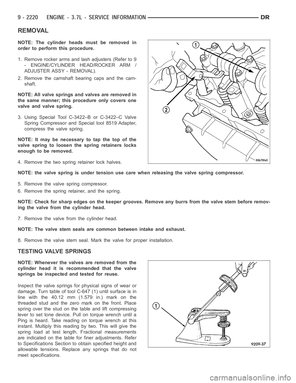
3. Using Special Tool C-3422–B or C-3422–C Valve
Spring Compressor and Special tool 8519 Adapter,
compress the valve spring.
NOTE: It may be necessary to tap the top of the
valve spring to loosen the spring retainers locks
enough to be removed.
4. Remove the two spring retainer lock halves.
NOTE: the valve spring is under tension use care when releasing the valve spring compressor.
5. Remove the valve spring compressor.
6. Remove the spring retainer, and the spring.
NOTE: Check for sharp edges on the keeper grooves. Remove any burrs from thevalvestembeforeremov-
ing the valve from the cylinder head.
7. Remove the valve from the cylinder head.
NOTE: The valve stem seals are common between intake and exhaust.
8. Remove the valve stem seal. Mark the valve for proper installation.
TESTING VALVE SPRINGS
NOTE: Whenever the valves are removed from the
cylinder head it is recommended that the valve
springs be inspected and tested for reuse.
Inspect the valve springs for physical signs of wear or
damage. Turn table of tool C-647 (1) until surface is in
line with the 40.12 mm (1.579 in.) mark on the
threaded stud and the zero mark on the front. Place
spring over the stud on the table and lift compressing
lever to set tone device. Pull on torque wrench until a
Ping is heard. Take reading on torque wrench at this
instant. Multiply this reading by two. This will give the
spring load at test length. Fractional measurements
are indicated on the table for finer adjustments. Refer
to Specifications Section to obtain specified height and
allowable tensions. Replace any springs that do not
meet specifications.
Page 1536 of 5267
HEAD-CYLINDER-RIGHT
DIAGNOSIS AND TESTING - HYDRAULIC LASH ADJUSTER
A tappet-like noise may be produced from several items. Check the followingitems.
1. Engine oil level too high or too low. This may cause aerated oil to enter the adjusters and cause them to be
spongy.
2. Insufficient running time after rebuilding cylinder head. Low speed runningupto1hourmayberequired.
3. Turn engine off and let set for a few minutes before restarting. Repeat this several times after engine has
reached normal operating temperature.
4. Low oil pressure.
5. The oil restrictor in cylinder head gasket or the oil passage to the cylinder head is plugged with debris.
6. Airingestedintooilduetobrokenorcrackedoilpumppickup.
7. Worn valve guides.
8. Rocker arm ears contacting valve spring retainer.
9. Rocker arm loose, adjuster stuck or at maximum extension and still leaves lash in the system.
10. Oil leak or excessive cam bore wear in cylinder head.
11. Faulty lash adjuster.
a. Check lash adjusters for sponginess while installed in cylinder head and cam on camshaft at base circle.
Depress part of rocker arm over adjuster. Normal adjusters should feel firm when pressed quickly. When pressed
very slowly, lash adjusters should collapse.
b. Remove suspected lash adjusters, and replace.
c. Before installation, make sure adjusters are full of oil. This can be verified by little plunger travel when lash
adjuster is depressed quickly.
REMOVAL
REMOVAL RIGHT CYLINDER HEAD
1. Disconnect battery negative cable.
2. Raise the vehicle on a hoist.
3. Disconnect the exhaust pipe at the right side
exhaust manifold.
4. Drain the engine coolant (Refer to 7 - COOLING -
STANDARD PROCEDURE).
5. Lower the vehicle.
6. Remove the intake manifold (Refer to 9 - ENGINE/
MANIFOLDS/INTAKE MANIFOLD - REMOVAL).
7. Remove the cylinder head cover (Refer to 9 -
ENGINE/CYLINDER HEAD - REMOVAL).
8. Remove the fan shroud (Refer to 7 - COOLING/
ENGINE/RADIATOR FAN - REMOVAL).
9. Remove oil fill housing from cylinder head.
10. Remove accessory drive belt (Refer to 7 - COOL-
ING/ACCESSORY DRIVE/DRIVE BELTS -
REMOVAL).
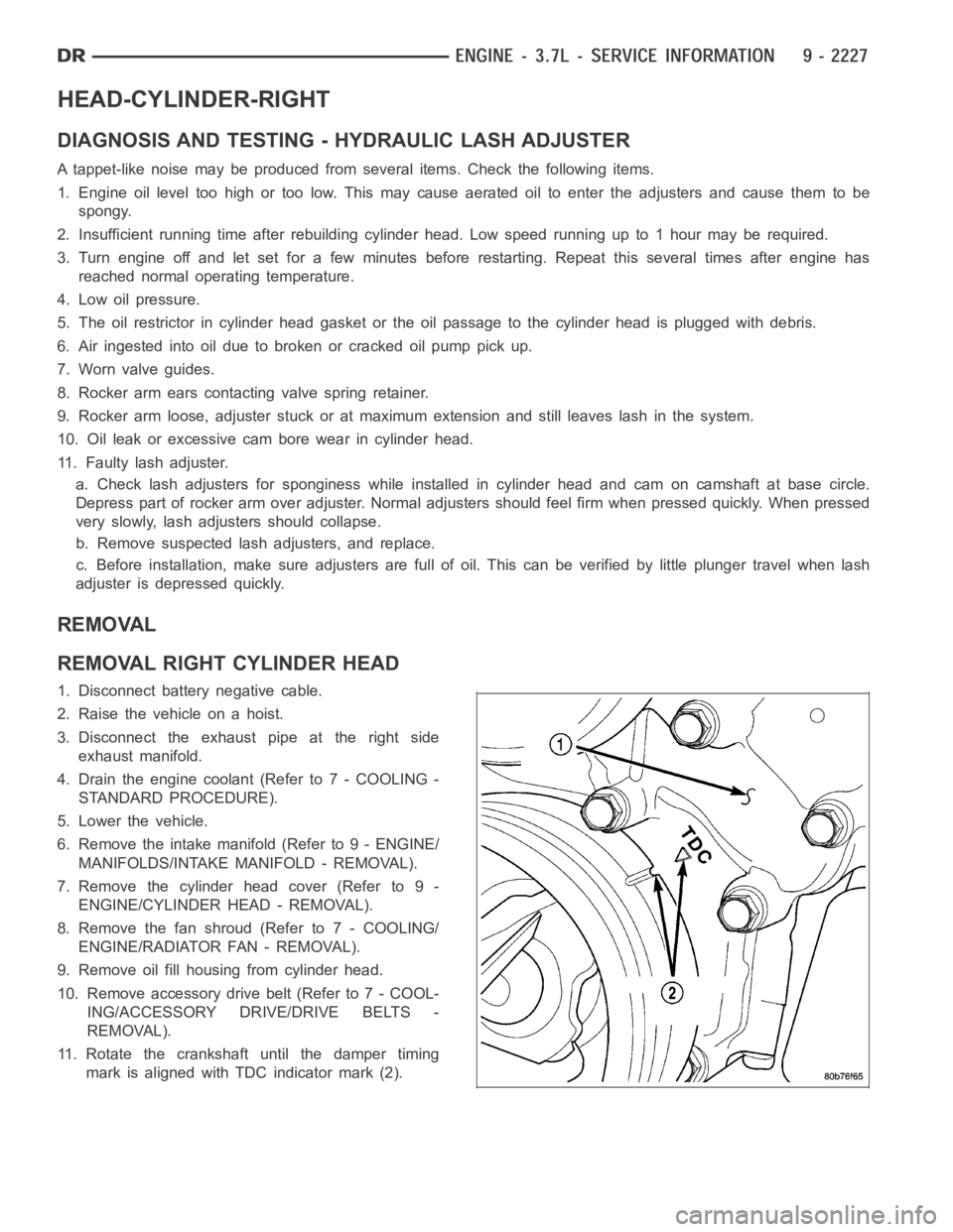
11. Rotate the crankshaft until the damper timing
mark is aligned with TDC indicator mark (2).
Page 1542 of 5267
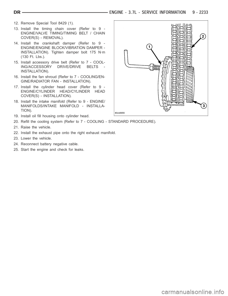
12. Remove Special Tool 8429 (1).
13. Install the timing chain cover (Refer to 9 -
ENGINE/VALVE TIMING/TIMING BELT / CHAIN
COVER(S) - REMOVAL).
14. Install the crankshaft damper (Refer to 9 -
ENGINE/ENGINE BLOCK/VIBRATION DAMPER -
INSTALLATION). Tighten damper bolt 175 Nꞏm
(130 Ft. Lbs.).
15. Install accessory drive belt (Refer to 7 - COOL-
ING/ACCESSORY DRIVE/DRIVE BELTS -
INSTALLATION).
16. Install the fan shroud (Refer to 7 - COOLING/EN-
GINE/RADIATOR FAN - INSTALLATION).
17. Install the cylinder head cover (Refer to 9 -
ENGINE/CYLINDER HEAD/CYLINDER HEAD
COVER(S) - INSTALLATION).
18. Install the intake manifold (Refer to 9 - ENGINE/
MANIFOLDS/INTAKE MANIFOLD - INSTALLA-
TION).
19. Install oil fill housing onto cylinder head.
20. Refill the cooling system (Refer to 7 - COOLING - STANDARD PROCEDURE).
21. Raise the vehicle.
22. Install the exhaust pipe onto the right exhaust manifold.
23. Lower the vehicle.
24. Reconnect battery negative cable.
25. Start the engine and check for leaks.
Page 1553 of 5267
BLOCK-ENGINE
DESCRIPTION
The cylinder block is made of cast iron.The block is a closed deck design with the left bank forward. To provide
high rigidity and improved NVH an enhanced compacted graphite bedplate isbolted to the block. The block design
allows coolant flow between the cylinders bores, and an internal coolant bypass to a single poppet inlet thermostat
is included in the cast aluminum front cover.
STANDARD PROCEDURE - CYLINDER BORE HONING
Before honing, stuff plenty of clean shop towels under
the bores and over the crankshaft to keep abrasive
materials from entering the crankshaft area.
1. Used carefully, the Cylinder Bore Sizing Hone
C-823, equipped with 220 grit stones, is the best
tool for this job. In addition to deglazing, it will
reduce taper and out-of-round, as well as removing
light scuffing, scoring and scratches. Usually, a few
strokes will clean up a bore and maintain the
required limits.
CAUTION: DO NOT use rigid type hones to remove
cylinder wall glaze.
2. Deglazing of the cylinder walls may be done if the
cylinder bore is straight and round. Use a cylinder
surfacing hone, Honing Tool C-3501, equipped with
280 grit stones (C-3501-3810). about 20-60
strokes, depending on the bore condition, will be
sufficient to provide a satisfactory surface. Using
honing oil C-3501-3880, or a light honing oil, avail-
able from major oil distributors.
CAUTION: DO NOT use engine or transmission oil, mineral spirits, or kerosene.
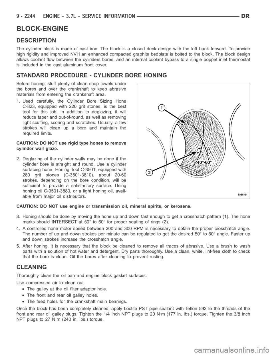
3. Honing should be done by moving the hone up and down fast enough to get a crosshatch pattern (1). The hone
marks should INTERSECT at 50° to 60° for proper seating of rings (2).
4. A controlled hone motor speed between 200 and 300 RPM is necessary to obtain the proper crosshatch angle.
The number of up and down strokes per minute can be regulated to get the desired 50° to 60° angle. Faster up
and down strokes increase the crosshatch angle.
5. After honing, it is necessary that the block be cleaned to remove all traces of abrasive. Use a brush to wash
parts with a solution of hot water and detergent. Dry parts thoroughly. Usea clean, white, lint-free cloth to check
that the bore is clean. Oil the bores after cleaning to prevent rusting.
CLEANING
Thoroughly clean the oil pan and engine block gasket surfaces.
Use compressed air to clean out:
The galley at the oil filter adaptor hole.
The front and rear oil galley holes.
The feed holes for the crankshaft main bearings.
Once the block has been completely cleaned, apply Loctite PST pipe sealantwith Teflon 592 to the threads of the
front and rear oil galley plugs. Tighten the 1/4 inch NPT plugs to 20 Nꞏm (177in. lbs.) torque. Tighten the 3/8 inch
NPT plugs to 27 Nꞏm (240 in. lbs.) torque.
Page 1560 of 5267
BEARINGS-CRANKSHAFT MAIN
STANDARD PROCEDURE
MAIN BEARING FITTING
SELECT FIT IDENTIFICATION
The main bearings are “select fit” to achieve proper oil
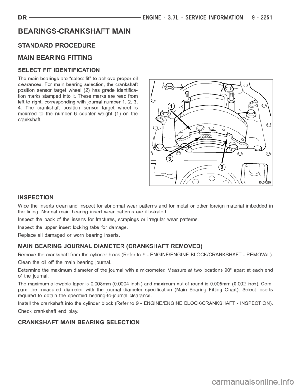
clearances. For main bearing selection, the crankshaft
position sensor target wheel (2) has grade identifica-
tion marks stamped into it. These marks are read from
left to right, corresponding with journal number 1, 2, 3,
4. The crankshaft position sensor target wheel is
mounted to the number 6 counter weight (1) on the
crankshaft.
INSPECTION
Wipe the inserts clean and inspect for abnormal wear patterns and for metalor other foreign material imbedded in
the lining. Normal main bearing insert wear patterns are illustrated.
Inspect the back of the inserts for fractures, scrapings or irregular wearpatterns.
Inspect the upper insert locking tabs for damage.
Replace all damaged or worn bearing inserts.
MAIN BEARING JOURNAL DIAMETER (CRANKSHAFT REMOVED)
Remove the crankshaft from the cylinder block (Refer to 9 - ENGINE/ENGINE BLOCK/CRANKSHAFT - REMOVAL).
Clean the oil off the main bearing journal.
Determine the maximum diameter of the journal with a micrometer. Measure at two locations 90° apart at each end
of the journal.
The maximum allowable taper is 0.008mm (0.0004 inch.) and maximum out of round is 0.005mm (0.002 inch). Com-
pare the measured diameter with the journal diameter specification (MainBearing Fitting Chart). Select inserts
required to obtain the specified bearing-to-journal clearance.
Install the crankshaft into the cylinder block (Refer to 9 - ENGINE/ENGINEBLOCK/CRANKSHAFT - INSPECTION).
Check crankshaft end play.
CRANKSHAFT MAIN BEARING SELECTION