2006 DODGE RAM SRT-10 check engine
[x] Cancel search: check enginePage 1408 of 5267
4.ASD RELAY
Install a substitute relay for the ASD Relay.
Attempt to startthe vehicle.
Did the engine start?
Ye s>>
Replace the ASD Relay.
Perform POWERTRAIN VERIFICATION TEST VER - 2.
No>>
Go To 5
5.(A14) FUSED B+ CIRCUITS
Turn the ignition off.
Remove the ASD Relay from the PDC.
Using a 12-volt test light, probe the (A14) Fused B+ circuits at the ASD Relay connector in the PDC.
Does the test light illuminate brightly?
Ye s>>
Go To 6
No>>
Repair the open or short to ground in the (A14) Fused B+ circuits. Inspect the related fuse and repair
as necessary.
Perform POWERTRAIN VERIFICATION TEST. (Refer to 9 - ENGINE - STANDARD PROCEDURE)
6.(K342) ASD RELAY OUTPUT CIRCUIT OPEN
Disconnect the PCM harness connectors.
Measure the resistance of the (K342) ASD Relay Output circuit from the ASD Relay cavity in the PDC to the PCM
harness connector.
Is the resistance below 5.0 ohms?
Ye s>>
Go To 7
No>>
Repair the open in the (K342)ASD Relay Output circuit.
Perform POWERTRAIN VERIFICATION TEST. (Refer to 9 - ENGINE - STANDARD PROCEDURE)
7.PCM
NOTE: Before continuing, check the PCM harness connector terminals for corrosion, damage, or terminal
push out. Repair as necessary.
Using the schematics as a guide, inspect the wire harness and connectors. Pay particular attention to all Power and
Ground circuits.
If there are no possible causes remaining, view repair.
Repair
Replace and program the Powertrain Control Module per Service Information.
Perform POWERTRAIN VERIFICATION TEST. (Refer to 9 - ENGINE - STANDARD PROCEDURE)
Page 1410 of 5267
When Monitored:
Engine running or cranking.
Set Condition:
When the failure counter reaches 20 for 2 consecutive trips.
Possible Causes
GOOD TRIP EQUAL TO ZERO
CMP WIRE HARNESS INSPECTION
TONE WHEEL/PULSE RING INSPECTION
CKP WIRE HARNESS INSPECTION
TONE WHEEL/PULSE RING INSPECTION
CHECKING INTERMITTENT CKP SIGNAL WITH LAB SCOPE
CAMSHAFT POSITION SENSOR
CRANKSHAFT POSITION SENSOR
Always perform the Pre-Diagnostic Troubleshooting procedure before proceeding. (Refer to 9 - ENGINE -
DIAGNOSIS AND TESTING)
1.GOOD TRIP EQUAL TO ZERO
Ignition on, engine not running.
WARNING: When the engine is operating, do not stand in a direct line with thefan. Do not put your hand
near the pulleys, belts, or fan. Do not wear loose clothing.
With the scan tool, read DTCs and record the related Freeze Frame data.
Start the engine and run until operating temp is reached. (Closed Loop)
If the DTC does not return right away it may be necessary to test drive the vehicle to duplicate the DTC.
Does the P1391 return?
Ye s>>
Go To 2
No>>
Refer to the INTERMITTENT CONDITIONSymptom (Diagnostic Procedure).
Perform POWERTRAIN VERIFICATION TEST. (Refer to 9 - ENGINE - STANDARD PROCEDURE)
2.INTERMITTENT CAM POSITION SENSOR SIGNAL
Turn the ignition off.
With the scan tool as a Dual Channel Lab Scope and Miller special tool #6801,backprobe the (K44) CMP Signal
circuit in the CMP harness connector and PCM harness connector.
WARNING: When the engine is operating, do not stand in a direct line with thefan. Do not put your hand
near the pulleys, belts, or fan. Do not wear loose clothing.
Start the engine.
Observe the lab scope screen.
Are there any irregular or missing signals?
Ye s>>
Go To 3
No>>
Go To 6
Page 1411 of 5267
3.CMP WIRE HARNESS INSPECTION
Visually inspect the related wire harness. Look for any chafed, pierced, pinched, or partially broken wires.
Visually inspect the related wire harness connectors. Look for broken, bent, pushed out, or corroded terminals.
Make sure the Crankshaft Position Sensor and the Camshaft Position Sensorare properly installed and the mount-
ing bolt(s) are torqued to specification.
Refer to any TSB that may apply.
Were any of the above conditions present?
Ye s>>
Repair as necessary
Perform POWERTRAIN VERIFICATION TEST. (Refer to 9 - ENGINE - STANDARD PROCEDURE)
No>>
Go To 4
4.TONE WHEEL/PULSE RING INSPECTION
Turn the ignition off.
Remove the Camshaft Position Sensor.
Inspect the Tone Wheel/Pulse Ring for damage, foreign material, or excessive movement.
Were any problems found?
Ye s>>
Repair or replace the Tone Wheel/Pulse Ring as necessary.
Perform POWERTRAIN VERIFICATION TEST. (Refer to 9 - ENGINE - STANDARD PROCEDURE)
No>>
Go To 5
5.CAMSHAFT POSITION SENSOR
If there are no possible causes remaining, view repair.
Repair
Replace the Camshaft Position Sensor.
Perform POWERTRAIN VERIFICATION TEST. (Refer to 9 - ENGINE - STANDARD PROCEDURE)
6.CHECKING CKP SIGNAL WITH THE SCAN TOOL LAB
Turn the ignition off.
With the scan tool as a Dual Channel Lab Scope and the Miller special tool #6801, backprobe the (K24) CKP Signal
circuit in the CKP harness connector and PCM harness connector.
WARNING: When the engine is operating, do not stand in a direct line with thefan. Do not put your hand
near the pulleys, belts, or fan. Do not wear loose clothing.
Start the engine.
Observe the lab scope screen.
Are there any irregular or missing signals?
Ye s>>
Go To 7
No>>
Go To 10
Page 1412 of 5267
7.CKP WIRE HARNESS INSPECTION
Visually inspect the related wire harness. Look for any chafed, pierced, pinched, or partially broken wires.
Visually inspect the related wire harness connectors. Look for broken, bent, pushed out, or corroded terminals.
Ensure the Crankshaft Position Sensor and the Camshaft Position Sensor are properly installed and the mounting
bolt(s) are torqued to specification.
Refer to any TSB that may apply.
Were any of the above conditions present?
Ye s>>
Repair as necessary
Perform POWERTRAIN VERIFICATION TEST. (Refer to 9 - ENGINE - STANDARD PROCEDURE)
No>>
Go To 8
8.TONE WHEEL/FLEX PLATE INSPECTION
Remove the Crankshaft Position Sensor.
Inspect the Tone Wheel/Flex Plate slots for damage, foreign material, or excessive movement.
Were any problems found?
Ye s>>
Repair or replace the Tone Wheel/Flex Plate as necessary.
Perform POWERTRAIN VERIFICATION TEST. (Refer to 9 - ENGINE - STANDARD PROCEDURE)
No>>
Go To 9
9.CRANKSHAFT POSITION SENSOR
If there are no possible causes remaining, view repair.
Repair
Replace the Crankshaft Position Sensor.
Perform POWERTRAIN VERIFICATION TEST. (Refer to 9 - ENGINE - STANDARD PROCEDURE)
10.CHECKING CKP SIGNAL WITH LAB SCOPE
NOTE: The conditions that set this DTC are not present at this time. The following test may help in identi-
fying the intermittent condition.
Turn the ignition off.
With the scan tool as a Dual Channel Lab Scope and the Miller special tool #6801, backprobe the (K24) CKP Signal
circuit in the PCM harness connector and CKP harness connector.
WARNING: When the engine is operating, do not stand in a direct line with thefan. Do not put your hand
near the pulleys, belts, or fan. Do not wear loose clothing.
Start the engine.
Carefully wiggle the related wire harness and gently tap on the CKP sensor.
Compare the Channel 1 reading to the Channel 2 reading on the lab scope screen.
Both of the readings should be the same.
Were any of the above conditions present?
Ye s>>
Repair the wiring or connector concern.
Perform POWERTRAIN VERIFICATION TEST. (Refer to 9 - ENGINE - STANDARD PROCEDURE)
No>>
Te s t C o m p l e t e .
Page 1413 of 5267
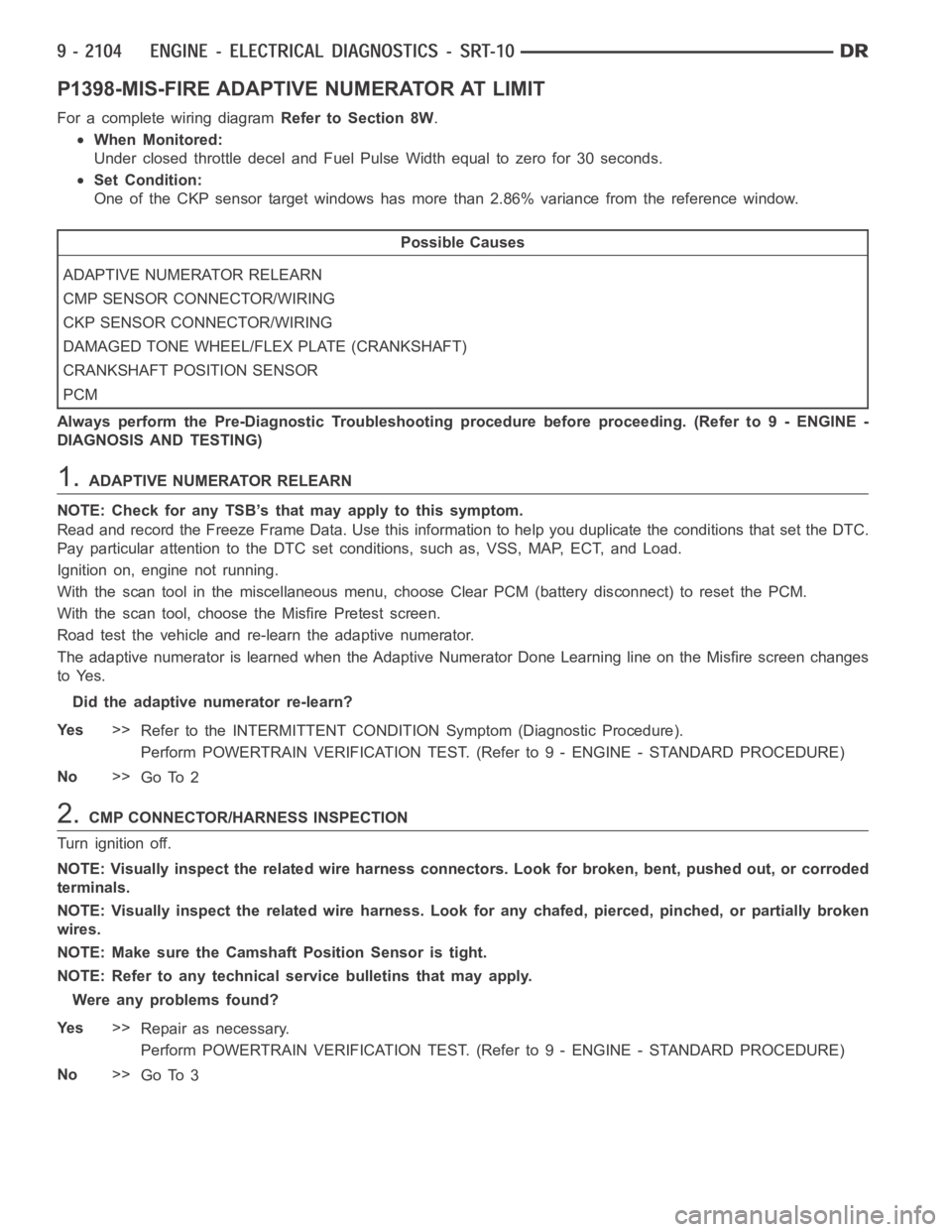
P1398-MIS-FIRE ADAPTIVE NUMERATOR AT LIMIT
For a complete wiring diagramRefer to Section 8W.
When Monitored:
Under closed throttle decel and Fuel Pulse Width equal to zero for 30 seconds.
Set Condition:
One of the CKP sensor target windows has more than 2.86% variance from the reference window.
Possible Causes
ADAPTIVE NUMERATOR RELEARN
CMP SENSOR CONNECTOR/WIRING
CKP SENSOR CONNECTOR/WIRING
DAMAGED TONE WHEEL/FLEX PLATE (CRANKSHAFT)
CRANKSHAFT POSITION SENSOR
PCM
Always perform the Pre-Diagnostic Troubleshooting procedure before proceeding. (Refer to 9 - ENGINE -
DIAGNOSIS AND TESTING)
1.ADAPTIVE NUMERATOR RELEARN
NOTE: Check for any TSB’s that may apply to this symptom.
Read and record the Freeze Frame Data. Use this information to help you duplicate the conditions that set the DTC.
Pay particular attention to the DTC set conditions, such as, VSS, MAP, ECT,and Load.
Ignition on, engine not running.
With the scan tool in the miscellaneous menu, choose Clear PCM (battery disconnect) to reset the PCM.
With the scan tool, choose the Misfire Pretest screen.
Road test the vehicle and re-learn the adaptive numerator.
The adaptive numerator is learned when the Adaptive Numerator Done Learning line on the Misfire screen changes
to Yes.
Did the adaptive numerator re-learn?
Ye s>>
Refer to the INTERMITTENT CONDITIONSymptom (Diagnostic Procedure).
Perform POWERTRAIN VERIFICATION TEST. (Refer to 9 - ENGINE - STANDARD PROCEDURE)
No>>
Go To 2
2.CMP CONNECTOR/HARNESS INSPECTION
Turn ignition off.
NOTE: Visually inspect the related wire harness connectors. Look for broken, bent, pushed out, or corroded
terminals.
NOTE: Visually inspect the related wire harness. Look for any chafed, pierced, pinched, or partially broken
wires.
NOTE: Make sure the Camshaft Position Sensor is tight.
NOTE: Refer to any technical service bulletins that may apply.
Were any problems found?
Ye s>>
Repair as necessary.
Perform POWERTRAIN VERIFICATION TEST. (Refer to 9 - ENGINE - STANDARD PROCEDURE)
No>>
Go To 3
Page 1414 of 5267
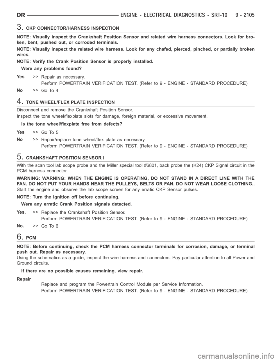
3.CKP CONNECTOR/HARNESS INSPECTION
NOTE: Visually inspect the Crankshaft Position Sensor and related wire harness connectors. Look for bro-
ken, bent, pushed out, or corroded terminals.
NOTE: Visually inspect the related wire harness. Look for any chafed, pierced, pinched, or partially broken
wires.
NOTE:VerifytheCrankPositionSensorisproperlyinstalled.
Were any problems found?
Ye s>>
Repair as necessary.
Perform POWERTRAIN VERIFICATION TEST. (Refer to 9 - ENGINE - STANDARD PROCEDURE)
No>>
Go To 4
4.TONE WHEEL/FLEX PLATE INSPECTION
Disconnect and remove the Crankshaft Position Sensor.
Inspect the tone wheel/flexplate slots for damage, foreign material, or excessive movement.
Is the tone wheel/flexplate free from defects?
Ye s>>
Go To 5
No>>
Repair/replace tone wheel/flex plate as necessary.
Perform POWERTRAIN VERIFICATION TEST. (Refer to 9 - ENGINE - STANDARD PROCEDURE)
5.CRANKSHAFT POSITION SENSOR l
With the scan tool lab scope probe and the Miller special tool #6801, back probe the (K24) CKP Signal circuit in the
PCM harness connector.
WARNING: WARNING: WHEN THE ENGINE IS OPERATING, DO NOT STAND IN A DIRECT LINEWITHTHE
FAN. DO NOT PUT YOUR HANDS NEAR THE PULLEYS, BELTS OR FAN. DO NOT WEAR LOOSE CLOTHING..
Start the engine and observe the lab scope screen for any erratic CKP Sensorpulses.
NOTE: Turn the ignition off before continuing.
Were any erratic Crank Position signals detected.
Ye s .>>
Replace the Crankshaft Position Sensor.
Perform POWERTRAIN VERIFICATION TEST. (Refer to 9 - ENGINE - STANDARD PROCEDURE)
No.>>
Go To 6
6.PCM
NOTE: Before continuing, check the PCM harness connector terminals for corrosion, damage, or terminal
push out. Repair as necessary.
Using the schematics as a guide, inspect the wire harness and connectors. Pay particular attention to all Power and
Ground circuits.
If there are no possible causes remaining, view repair.
Repair
Replace and program the Powertrain Control Module per Service Information.
Perform POWERTRAIN VERIFICATION TEST. (Refer to 9 - ENGINE - STANDARD PROCEDURE)
Page 1416 of 5267
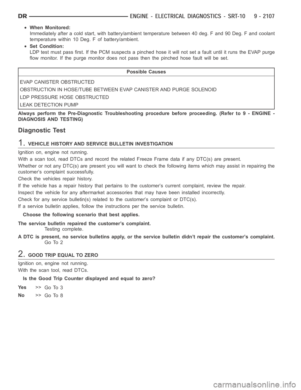
When Monitored:
Immediately after a cold start, with battery/ambient temperature between 40 deg. F and 90 Deg. F and coolant
temperature within 10 Deg. F of battery/ambient.
Set Condition:
LDP test must pass first. If the PCM suspects a pinched hose it will not set a fault until it runs the EVAP purge
flow monitor. If the purge monitor does not pass then the pinched hose faultwill be set.
Possible Causes
EVAP CANISTER OBSTRUCTED
OBSTRUCTION IN HOSE/TUBE BETWEEN EVAP CANISTER AND PURGE SOLENOID
LDP PRESSURE HOSE OBSTRUCTED
LEAK DETECTION PUMP
Always perform the Pre-Diagnostic Troubleshooting procedure before proceeding. (Refer to 9 - ENGINE -
DIAGNOSIS AND TESTING)
Diagnostic Test
1.VEHICLE HISTORY AND SERVICE BULLETIN INVESTIGATION
Ignition on, engine not running.
With a scan tool, read DTCs and record the related Freeze Frame data if any DTC(s) are present.
Whether or not any DTC(s) are present you will want to check the following items which may assist in repairing the
customer’s complaint successfully.
Check the vehicles repair history.
If the vehicle has a repair history that pertains to the customer’s currentcomplaint, review the repair.
Inspect the vehicle for any aftermarket accessories that may have been installed incorrectly.
Check for any service bulletin(s) related to the customer’s complaint or DTC(s).
If a service bulletin applies, follow the instructions per the service bulletin.
Choose the following scenario that best applies.
The service bulletin repaired the customer’s complaint.
Testing complete.
A DTC is present, no service bulletins apply, or the service bulletin didn’t repair the customer’s complaint.
Go To 2
2.GOOD TRIP EQUAL TO ZERO
Ignition on, engine not running.
With the scan tool, read DTCs.
Is the Good Trip Counter displayed and equal to zero?
Ye s>>
Go To 3
No>>
Go To 8
Page 1417 of 5267
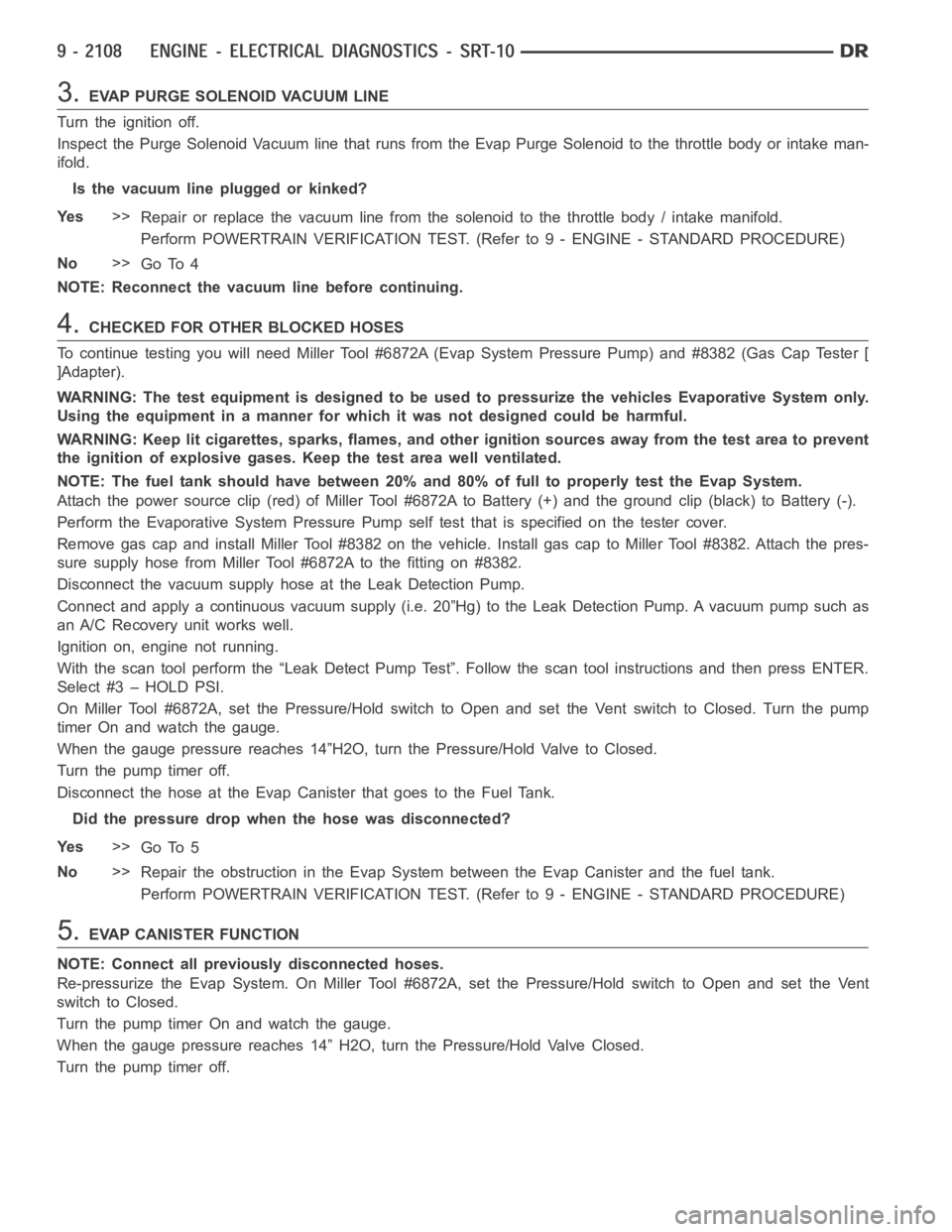
3.EVAP PURGE SOLENOID VACUUM LINE
Turn the ignition off.
Inspect the Purge Solenoid Vacuum line that runs from the Evap Purge Solenoid to the throttle body or intake man-
ifold.
Is the vacuum line plugged or kinked?
Ye s>>
Repair or replace the vacuum line from the solenoid to the throttle body / intake manifold.
Perform POWERTRAIN VERIFICATION TEST. (Refer to 9 - ENGINE - STANDARD PROCEDURE)
No>>
Go To 4
NOTE: Reconnect the vacuum line before continuing.
4.CHECKED FOR OTHER BLOCKED HOSES
To continue testing you will need Miller Tool #6872A (Evap System PressurePump) and #8382 (Gas Cap Tester [
]Adapter).
WARNING: The test equipment is designed to be used to pressurize the vehicles Evaporative System only.
Using the equipment in a manner for which it was not designed could be harmful.
WARNING: Keep lit cigarettes, sparks, flames, and other ignition sourcesaway from the test area to prevent
the ignition of explosive gases. Keep the test area well ventilated.
NOTE: The fuel tank should have between 20% and 80% of full to properly test the Evap System.
Attach the power source clip (red) of Miller Tool #6872A to Battery (+) and the ground clip (black) to Battery (-).
Perform the Evaporative System Pressure Pump self test that is specified on the tester cover.
Remove gas cap and install Miller Tool #8382 on the vehicle. Install gas capto Miller Tool #8382. Attach the pres-
sure supply hose from Miller Tool #6872A to the fitting on #8382.
Disconnect the vacuum supply hose at the Leak Detection Pump.
Connect and apply a continuous vacuum supply (i.e. 20”Hg) to the Leak Detection Pump. A vacuum pump such as
an A/C Recovery unit works well.
Ignition on, engine not running.
With the scan tool perform the “Leak Detect Pump Test”. Follow the scan toolinstructions and then press ENTER.
Select#3–HOLDPSI.
On Miller Tool #6872A, set the Pressure/Hold switch to Open and set the Ventswitch to Closed. Turn the pump
timer On and watch the gauge.
When the gauge pressure reaches 14”H2O, turn the Pressure/Hold Valve to Closed.
Turn the pump timer off.
Disconnect the hose at the Evap Canister that goes to the Fuel Tank.
Did the pressure drop when the hose was disconnected?
Ye s>>
Go To 5
No>>
Repair the obstruction in the Evap System between the Evap Canister and thefuel tank.
Perform POWERTRAIN VERIFICATION TEST. (Refer to 9 - ENGINE - STANDARD PROCEDURE)
5.EVAP CANISTER FUNCTION
NOTE: Connect all previously disconnected hoses.
Re-pressurize the Evap System. On Miller Tool #6872A, set the Pressure/Hold switch to Open and set the Vent
switch to Closed.
Turn the pump timer On and watch the gauge.
When the gauge pressure reaches 14” H2O, turn the Pressure/Hold Valve Closed.
Turn the pump timer off.