Page 2283 of 5267

PEDAL - ACCELERATOR
REMOVAL
The following procedure applies only to vehicles with-
out the Adjustable Pedal Package (code XAP).
The accelerator pedal is serviced as a complete
assembly including the bracket.
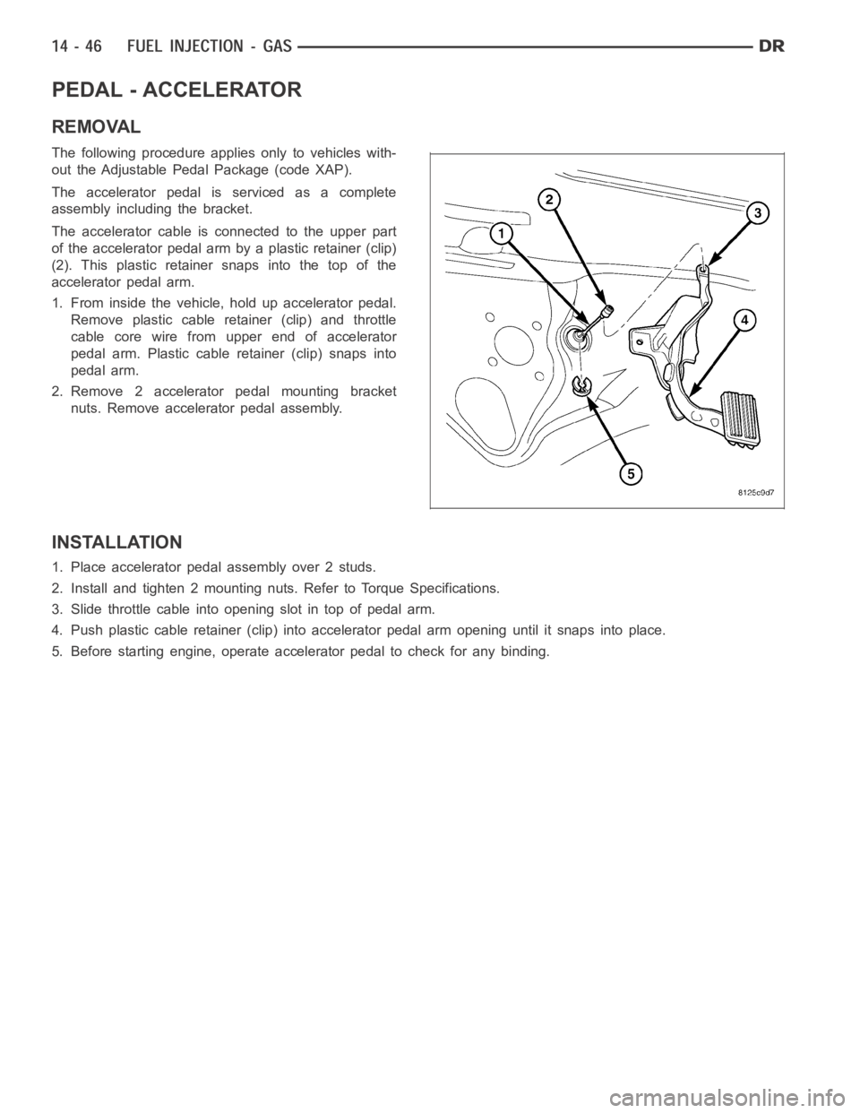
The accelerator cable is connected to the upper part
of the accelerator pedal arm by a plastic retainer (clip)
(2). This plastic retainer snaps into the top of the
accelerator pedal arm.
1. From inside the vehicle, hold up accelerator pedal.
Remove plastic cable retainer (clip) and throttle
cable core wire from upper end of accelerator
pedal arm. Plastic cable retainer (clip) snaps into
pedal arm.
2. Remove 2 accelerator pedal mounting bracket
nuts. Remove accelerator pedal assembly.
INSTALLATION
1. Place accelerator pedal assembly over 2 studs.
2. Install and tighten 2 mounting nuts. Refer to Torque Specifications.
3. Slide throttle cable into opening slot in top of pedal arm.
4. Push plastic cable retainer (clip) into accelerator pedal arm opening until it snaps into place.
5. Before starting engine, operate accelerator pedal to check for any binding.
Page 2289 of 5267
REMOVAL
3.7L V-6
The Crankshaft Position (CKP) sensor is mounted into
the right rear side of the cylinder block. It is positioned
and bolted into a machined hole.
1. Raise vehicle.
2. Disconnect sensor electrical connector.
3. Remove sensor mounting bolt (1).
4. Carefully twist sensor (2) from cylinder block.
5. Check condition of sensor O-ring (3).
4.7L V-8
The Crankshaft Position (CKP) sensor is located at
the right-rear side of the engine cylinder block. It is
positioned and bolted into a machined hole in the
engine block.
1. Raise vehicle.
2. Disconnect CKP electrical connector at sensor.
3. Remove CKP mounting bolt (2).
4. Carefully twist sensor (1) from cylinder block.
5. Remove sensor from vehicle.
6. Check condition of sensor O-ring.
Page 2290 of 5267
5.7L V-8
The Crankshaft Position (CKP) sensor (4) is located at
the right-rear side of the engine cylinder block. It is
positioned and bolted into a machined hole in the
engine block.
1. Raise vehicle.
2. Disconnect CKP electrical connector at sensor.
3. Remove CKP mounting bolt (3).
4. Carefully twist sensor (4) from cylinder block.
5. Remove sensor from vehicle.
6. Check condition of sensor O-ring.
8.3L - SRT-10
The sensor is located at the rear lower passenger side
of motor.
Page 2297 of 5267

12. Remove the fuel injector from the fuel rail.
INSTALLATION
3.7/ 4.7/ 5.7L
1. Install fuel injector(s) into fuel rail assembly and install retainingclip(s).
2. If same injector(s) is being reinstalled, install new O-ring(s).
3. Apply a small amount of clean engine oil to each injector O-ring. This will aid in installation.
4. Install fuel rail. (Refer to 14 - FUEL SYSTEM/FUEL DELIVERY/FUEL RAIL - INSTALLATION)
5. Start engine and check for fuel leaks.
8.3L - SRT-10
1. Install the fuel injectors to the fuel rail.
2. Install fuel rail under throttle body.
3. Apply a light coating of clean engine oiltotheO-ringonthenozzleendofeach injector.
4. Insert fuel injector nozzles into openings in intake manifold. Seat theinjectors in place. Tighten fuel rail bolts to
12 Nꞏm (105 in. lbs.).
5. Attach electrical connectors to fuel injectors.
6. Connect the electrical connector to the MAP sensor and Coolant Temperature sensor.
7. Connect the electrical connector to the TPS and Idle Air Control.
8. Install the wiring harness to the wiring clips under the throttle body.
9. Connect fuel supply tube to fuel rail. Refer to Quick Connect Fittings inthe Fuel Delivery section
10. Install the negative battery cable and install the battery cover.
11. Install the air cleaner assembly, refer to the Engine/Air Intake System/Air Cleaner Housing for more information.
12. Use the DRBIII
scan tool ASD Fuel System Test to pressurize the fuel system. Check for leaks.
Page 2298 of 5267

RELAY - FUEL PUMP
DESCRIPTION
The 5–pin, 12–volt, fuel pump relay is located in the Power Distribution Center (PDC). Refer to the label on the PDC
cover for relay location.
OPERATION
The Powertrain Control Module (PCM) energizes the electric fuel pump through the fuel pump relay. The fuel pump
relay is energized by first applying battery voltage to it when the ignition key is turned ON, and then applying a
ground signal to the relay from the PCM.
Whenever the ignition key is turned ON, the electric fuel pump will operate. But, the PCM will shut-down the ground
circuit to the fuel pump relay in approximately 1–3 seconds unless the engine is operating or the starter motor is
engaged.
REMOVAL
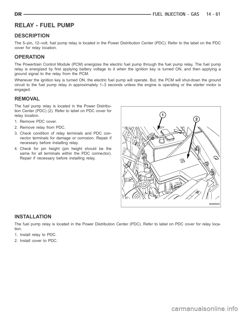
The fuel pump relay is located in the Power Distribu-
tion Center (PDC) (2). Refer to label on PDC cover for
relay location.
1. Remove PDC cover.
2. Remove relay from PDC.
3. Check condition of relay terminals and PDC con-
nector terminals for damage or corrosion. Repair if
necessary before installing relay.
4. Check for pin height (pin height should be the
same for all terminals within the PDC connector).
Repair if necessary before installing relay.
INSTALLATION
The fuel pump relay is located in the Power Distribution Center (PDC). Refer to label on PDC cover for relay loca-
tion.
1. Install relay to PDC.
2. Install cover to PDC.
Page 2326 of 5267
1. Remove air duct and air resonator box at throttle
body.
2. Disconnect electrical connector (2) at throttle body.
3. Remove 4 throttle body mounting bolts (4).
4. Remove throttle body from intake manifold.
5. Check condition of throttle body O-ring (2).
6. If the throttle body has been changed, the following
procedure must be performed:
a. Disconnect negative battery cable from battery.
Leave cable disconnected for approximately 90
seconds.
b. Reconnect cable to battery.
c. Turn ignition switch ON, but do not crank
engine.
d. Leave ignition switch ON for a minimum of 10
seconds. This will allow PCM to learn throttle
body electrical parameters.
Page 2334 of 5267

6. Remove cable housing at APPS bracket by pressing on release tab with a small screwdriver.To prevent cable
housing breakage, press on tab only enough to release cable from APPS bracket.
INSTALLATION
3.7L V-6
1. Slide accelerator cable plastic mount into throttle body mounting bracket. Continue sliding until release tab is
aligned to hole in mounting bracket.
2. Hold throttle in wide open position. While held in this position, slide throttle cable pin into throttle body bellcrank.
3. Push cable housing into rubber grommet and through opening in dash panel.
4. From inside vehicle, install metal clip holding cable to dashpanel.
5. From inside vehicle, slide throttle cable core wire into opening (slot)in top of pedal arm.
6. Push plastic cable retainer (clip) into pedal arm opening until it snapsin place.
7. Install air resonator tube to throttle body.
8. Before starting engine, operate accelerator pedal to check for any binding.
4.7L V-8
1. Slide accelerator cable plastic mount into bracket. Continue sliding until tab is aligned to hole in mounting
bracket.
2. Route accelerator cable over top of cable cam.
3. Connect cable end to throttle body bellcrank pin (snaps on rearward).
4. Slide rubber grommet away from plastic cable housing.
5. Install rubber grommet into dash panel until seated.
6. Push cable housing into rubber grommet and through opening in dash panel.
7. From inside vehicle, install clip holding cable to dashpanel.
8. From inside vehicle, slide throttle cable core wire into opening in top of pedal arm.
9. Push cable retainer (clip) into pedal arm opening until it snaps in place.
10. Snap cable into dashpanel routing clip.
11. Install air resonator tube to throttle body.
12. Before starting engine, operate accelerator pedal to check for any binding.
5.7L V-8
1. Attach cable to Accelerator Pedal Position Sensor (APPS). Refer to APPSRemoval / Installation.
2. Push cable housing into rubber grommet and through opening in dash panel.
3. From inside vehicle, install clip holding cable to dashpanel.
4. From inside vehicle, slide throttle cable core wire into opening in top of pedal arm.
5. Push cable retainer (clip) into pedal arm opening until it snaps in place.
6. Before starting engine, operate accelerator pedal to check for any binding.
7. If necessary, use DRB III
Scan Tool to erase any APPS Diagnostic Trouble Codes (DTC’s) from PCM.
Page 2338 of 5267
INSTALLATION
3.7L V-6
The Throttle Position Sensor (TPS) (1) is mounted to
the throttle body.
The throttle shaft end of throttle body slides into a
socket in TPS. The TPS must be installed so that it
can be rotated a few degrees. (If sensor will not
rotate, install sensor with throttle shaft on other side of
socket tangs). The TPS will be under slight tension
when rotated.
1. Install TPS and retaining screws.
2. Tighten screws to 7 Nꞏm (60 in. lbs.) torque.
3. Connect TPS electrical connector to TPS.
4. Manually operate throttle (by hand) to check for
any TPS binding before starting engine.
5. Install air cleaner tube to throttle body.