Page 2366 of 5267
SENSOR - FUEL PRESSURE
DESCRIPTION
The fuel pressure sensor is mounted vertically near the top/center of the fuel rail.
OPERATION
The fuel pressure sensor monitors actual high-pressure within the fuel rail. An output signal from this sensor (relat-
ing to fuel pressure) is sent to the Engine Control Module (ECM).
REMOVAL
The fuel pressure sensor (4) is mounted vertically
near the top/center of the fuel rail.
1. Disconnect electrical connector (1) at sensor.
2. Remove sensor from fuel rail.
3. Inspect sensor sealing surface.
INSTALLATION
1. Inspect fuel pressure sensor sealing surface.
2. Lubricate sensor threads with clean diesel fuel.
3. Install sensor (4) into fuel rail.
4. To prevent leaks, sensormustbe tightened to 70
Nꞏm (52 ft. lbs.).
5. Connect electrical connector to sensor.
6. Start engine and check for fuel leaks.
Page 2370 of 5267
INSTALLATION
1. If fuel tank is to be replaced, install fuel tank mod-
ule into tank. (Refer to 14 - FUEL SYSTEM/FUEL
DELIVERY/FUEL TANK MODULE - REMOVAL).
2. Position fuel tank (1) to hydraulic jack.
3. Raise tank until positioned near body.
4. Connect fuel tank module electrical connector at
top of tank.
5. Connect fuel supply and return lines to tank mod-
ule.
6. Continue raising tank until positioned snug to body.
7. Install and position both tank support straps (4).
Install 2 fuel tank strap nuts and tighten to 41 Nꞏm
(30 ft. lbs.).Tighten rear strap nut first.
8. Remove hydraulic jack.
9. Connect rubber fill hose to fuel fill tube and tighten
clamp.
10. Install tire / wheel (if necessary).
11. Lower vehicle.
12. Fill fuel tank with fuel.
13. Start engine and check for fuel leaks near top of module.
Page 2373 of 5267

PUMP - FUEL TRANSFER
DESCRIPTION
The fuel transfer pump (fuel lift pump) is part of the fuel pump module. The fuel pump module is located in the fuel
tank. The 12–volt electric pump is operated and controlled by the Engine Control Module (ECM). The ECM controls
a relay in the Intelligent Power Module(IPM) for transfer pump operation.
OPERATION
The purpose of the fuel transfer pump is to supply (transfer) a low-pressure fuel source:fromthe fuel tank,through
the fuel filter/water separator andtothe fuel injection pump. Here, the low-pressure is raised to a high-pressure by
the fuel injection pump for operation of the high-pressure fuel injectors. Check valves within the pump, control direc-
tion of fuel flow and prevent fuel bleed-back during engine shut down.
Maximum current flow to the pump is 5 amperes.
With the engine running, the pump has a 100 percent duty-cycle.
The transfer pump is self-priming: When the key is first turned on (withoutcranking engine), the pump will operate
for approximately 2 seconds and then shut off (Note: When ambient temperatures are cold enough to cause the
intake air heaters to operate, the fuel lift pump will operate during the entire intake air pre-heat cycle). The pump will
also operate for up to 25 seconds after the starter is engaged, and then disengaged and the engine is not running.
The pump shuts off immediately if the key is on and the engine stops running.
The fuel volume of the transfer pump will always provide more fuel than the fuel injection pump requires. Excess
fuel is returned from the injection pump through an overflow valve, and then back to the fuel tank.
REMOVAL
The fuel transfer pump (fuel lift pump) is a part of the fuel tank module. It is not serviced separately. Refer to Fuel
Tank Module Removal or Installation for procedures (Refer to 14 - FUEL SYSTEM/FUEL DELIVERY/FUEL TANK
MODULE - REMOVAL).
INSTALLATION
The fuel transfer pump (fuel lift pump) is a part of the fuel tank module. It is not serviced separately (Refer to 14 -
FUEL SYSTEM/FUEL DELIVERY/FUEL TANK MODULE - INSTALLATION).
Page 2380 of 5267

SENSOR-CAMSHAFT POSITION
DESCRIPTION
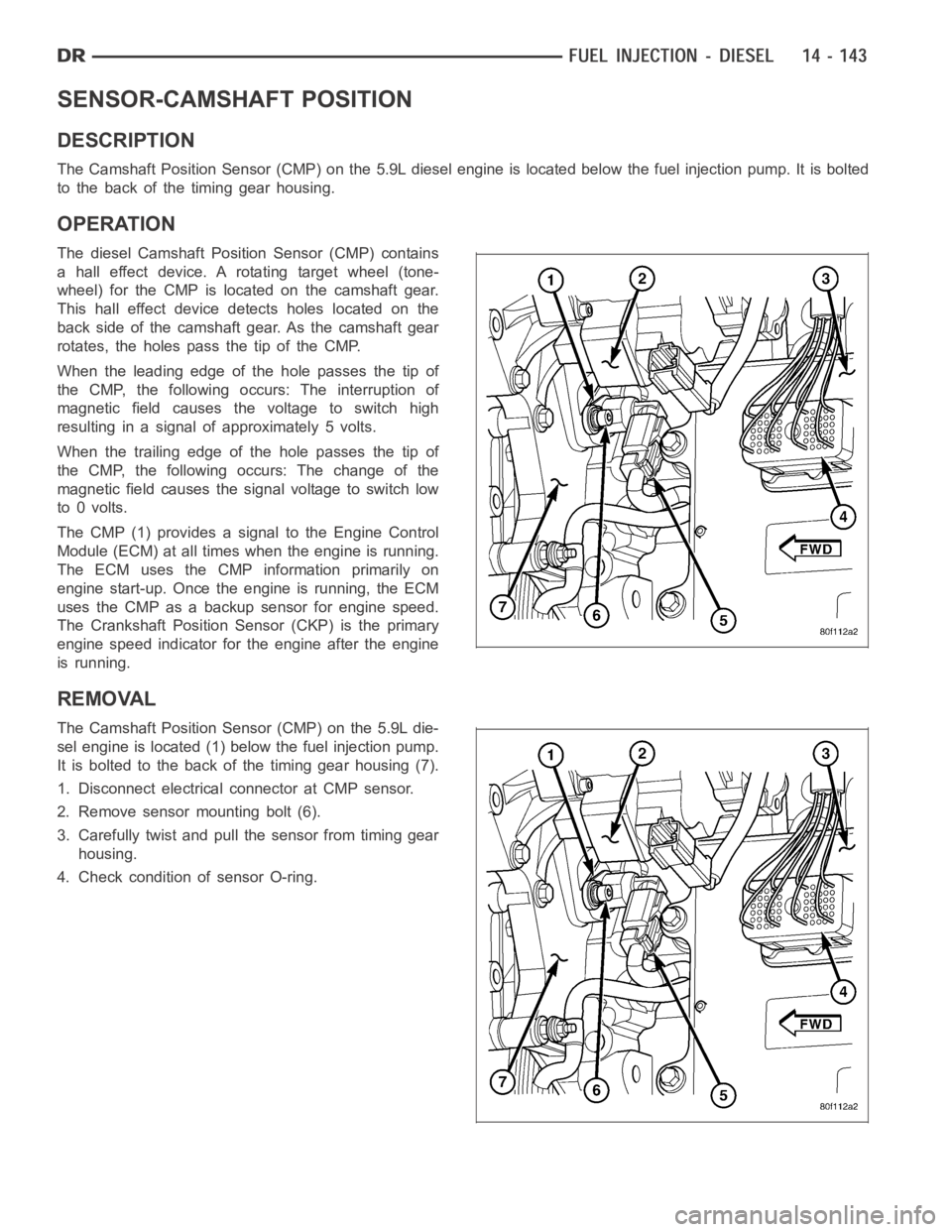
The Camshaft Position Sensor (CMP) on the 5.9L diesel engine is located below the fuel injection pump. It is bolted
to the back of the timing gear housing.
OPERATION
The diesel Camshaft Position Sensor (CMP) contains
a hall effect device. A rotating target wheel (tone-
wheel) for the CMP is located on the camshaft gear.
This hall effect device detects holes located on the
back side of the camshaft gear. As the camshaft gear
rotates, the holes pass the tip of the CMP.
When the leading edge of the hole passes the tip of
the CMP, the following occurs: The interruption of
magnetic field causes the voltage to switch high
resulting in a signal of approximately 5 volts.
When the trailing edge of the hole passes the tip of
the CMP, the following occurs: The change of the
magnetic field causes the signal voltage to switch low
to 0 volts.
The CMP (1) provides a signal to the Engine Control
Module (ECM) at all times when the engine is running.
TheECMusestheCMPinformationprimarilyon
engine start-up. Once the engine is running, the ECM
uses the CMP as a backup sensor for engine speed.
The Crankshaft Position Sensor (CKP) is the primary
engine speed indicator for the engine after the engine
is running.
REMOVAL
The Camshaft Position Sensor (CMP) on the 5.9L die-
sel engine is located (1) below the fuel injection pump.
It is bolted to the back of the timing gear housing (7).
1. Disconnect electrical connector at CMP sensor.
2. Remove sensor mounting bolt (6).
3. Carefully twist and pull the sensor from timing gear
housing.
4. Check condition of sensor O-ring.
Page 2393 of 5267
INSTALLATION
1. Clean any dirt/debris from top of intake manifold
and bottom of fuel rail.
2. Position fuel rail to top of manifold and install 3
mounting bolts (1) finger tight.
3. Install all high-pressure lines to rail (Refer to 14 -
FUEL SYSTEM/FUEL DELIVERY/FUEL LINES -
REMOVAL) (Refer to 14 - FUEL SYSTEM/FUEL
DELIVERY/FUEL LINES - INSTALLATION). Torque
to 30 Nꞏm (22 ft. lbs.).
4. Tighten 3 mounting bolts at fuel rail. Torque bolts to
24 Nꞏm (18 ft. lbs.).
5. Reposition wiring harness to intake elbow and
install nut.
6. Install and tighten fuel limiting valve banjo bolt.
Copper washer against fuel limiting valve, rubber
seal against banjo bolt. Torque to 24 Nꞏm (18 ft.
lbs.).
7. Connect electrical connector to fuel pressure sen-
sor.
8. Position 2 positive (+) cables to intake heater
studs. Install 2 nuts.
9. Connect battery cables to both batteries.
10. Start engine and check for leaks.
Page 2403 of 5267
5. Check condition of sensor O-ring (2).
INSTALLATION
1. Check condition of sensor o-ring.
2. Lubricate sensor o-ring and sensor hole in intake
manifold cover with clean engine oil.
3. Clean sensor mounting area at intake manifold (1).
4. Position sensor (2) into intake manifold.
5. Install and tighten 2 sensor mounting screws to 1
Nꞏm (9 in. lbs.) torque.
6. Connect electrical connector to sensor.
Page 2407 of 5267

STEERING
DESCRIPTION
CAUTION: MOPARATF+4 is to be used in the power steering system. No other power steering or auto-
matic transmission fluid is to be used in the system. Damage may result to the power steering pump and
system if any other fluid is used, and do not overfill.
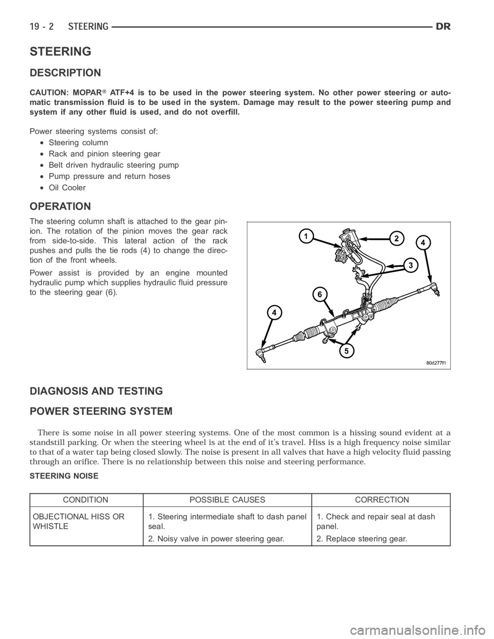
Power steering systems consist of:
Steering column
Rack and pinion steering gear
Belt driven hydraulic steering pump
Pump pressure and return hoses
Oil Cooler
OPERATION
The steering column shaft isattached to the gear pin-
ion. The rotation of the pinion moves the gear rack
from side-to-side. This lateral action of the rack
pushes and pulls the tie rods (4) to change the direc-
tion of the front wheels.
Power assist is provided by an engine mounted
hydraulic pump which supplies hydraulic fluid pressure
to the steering gear (6).
DIAGNOSIS AND TESTING
POWER STEERING SYSTEM
STEERING NOISE
CONDITION POSSIBLE CAUSES CORRECTION
OBJECTIONAL HISS OR
WHISTLE1. Steering intermediate shaft to dash panel
seal.1. Check and repair seal at dash
panel.
2. Noisy valve in power steering gear. 2. Replace steering gear.
Page 2410 of 5267

FLOW AND PRESSURE TEST
1. Check the power steering belt to ensure it is in good condition and adjusted properly.
2. Connect pressure gauge hose from the Power Steering Analyzer to adapter6826.
3. Connect tube 6825A to Power Steering Analyzer test valve end.
4. Disconnect the high pressure hose from the power steering pump.
5. Connect the tube 6825A to the pump fitting.
6. Connect the power steering hose from the steering gear to the adapter 6826.
NOTE: If fluid leaked from the steering system, it should be filled to correct lervel prior to starting the
engine.
7. Open the test valve completely.
8. Start engine and let idle long enough to circulate power steering fluid through flow/pressure test gauge and to get
air out of the fluid. Then shut off engine.
9. Check fluid level, add fluid as necessary. Start engine again and let idle.
10. Gauge should read below 862 kPa (125 psi), if above, inspect the hoses for restrictions and repair as neces-
sary. The initial pressure reading should be in the range of 345-552 kPa (50-80 psi).
11. Increase the engine speed to 1500 RPM and read the flow meter. If the flowrate (GPM) is below specification,
(refer to pump specification chart for GPM) the pump should be replaced.
CAUTION: The following test procedure involves testing maximum pump pressure output and flow control
valve operation. Do not leave valve closed for more than three seconds as the pump could be damaged.
12. Close valve fully three times and record highest pressure indicated each time.All three readings must be
above specifications and within 345 kPa (50 psi) of each other.
Pressures above specifications but not within 345 kPa (50 psi) of each other, replace pump.
Pressures within 345 kPa (50 psi) of each other but below specifications, replace pump.
13. Open the test valve and turn the steering wheel to the extreme left and right positions three times against the
stops. Record the highest pressure reading at each position. Compare readings to the pump specifications
chart. If pressures readings are not within 50 psi of each other, the gear isleaking internally and must be
replaced.
CAUTION: Do not force the pump to operate against the stops for more than 2 to3 seconds at a time
because, pump damage will result.
PUMP SPECIFICATION
ENGINE RELIEF PRESSURE ± 65 FLOW RATE (GPM) AT 1500 RPM
1500 series 11032 kPa (1615 ± 65 psi) 3.1 - 3.5
2500 & 3500
series12400 kPa (1800 ± 50 psi) 3.5 - 4.0