2006 DODGE RAM SRT-10 ECO mode
[x] Cancel search: ECO modePage 3071 of 5267
SWITCH-TOW/HAUL OVERDRIVE
DESCRIPTION
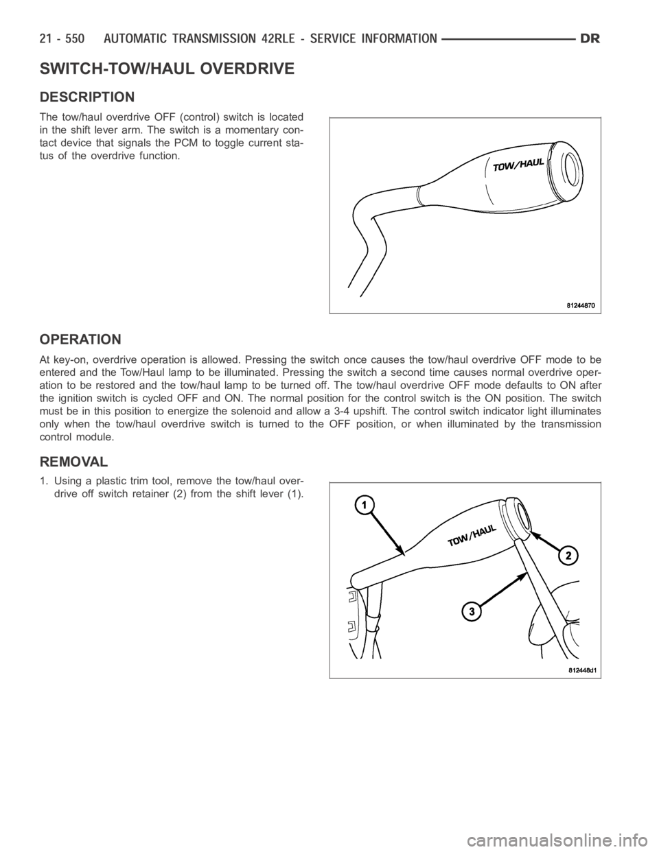
The tow/haul overdrive OFF (control) switch is located
in the shift lever arm. The switch is a momentary con-
tact device that signals the PCM to toggle current sta-
tus of the overdrive function.
OPERATION
At key-on, overdrive operation is allowed. Pressing the switch once causes the tow/haul overdrive OFF mode to be
entered and the Tow/Haul lamp to be illuminated. Pressing the switch a second time causes normal overdrive oper-
ationtoberestoredandthetow/haullamptobeturnedoff.Thetow/hauloverdrive OFF mode defaults to ON after
the ignition switch is cycled OFF and ON. The normal position for the control switch is the ON position. The switch
must be in this position to energize the solenoid and allow a 3-4 upshift. The control switch indicator light illuminates
only when the tow/haul overdrive switch is turned to the OFF position, or when illuminated by the transmission
control module.
REMOVAL
1. Using a plastic trim tool, remove the tow/haul over-
drive off switch retainer (2) from the shift lever (1).
Page 3115 of 5267
P0602-CONTROL MODULE PROGRAMMING ERROR/NOT PROGRAMMED
For a complete wiring diagramRefer to Section 8W
Theory of Operation
The controller is programmed during manufacturing with generic softwareto facilitate testing. However, generic soft-
ware does not have the proper calibrations to control a transmission in a vehicle. The check for generic software is
made at power-up. If generic software is found , the MIL will light immediately and the MIL will stay on even if the
fault is cleared, until the proper software is installed. Note: Transmission will be placed in limp-in mode.
When Monitored:
Check for generic software is made at power-up
Set Condition:
If generic software is found, the MIL will light immediately. This DTC is designed to inform the technician that
the controller still has generic software installed.
Possible Causes
PCM - PROGRAMMING ERROR
Always perform the Pre-Diagnostic Troubleshooting procedure before proceeding. (Refer to 21 - TRANSMIS-
SION/TRANSAXLE/AUTOMATIC - 45RFE/545RFE - STANDARD PROCEDURE)
Diagnostic Test
1.CONTROL MODULE PROGRAMMING ERROR
NOTE: Controller is programmed with generic software and will not allow the correct vehicle Powertrain
management.
With the scan tool.
Record the vehicles controller part number.
Select Use Controller Part Number under the Flash Tab.
Flash the controller with the correct software.
Verify the controller flashed successfully.
Te s t C o m p l e t e
Perform 45RFE/545RFE TRANSMISSION VERIFICATION TEST - VER 1. (Refer to 21- TRANSMIS-
SION/TRANSAXLE/AUTOMATIC - 45RFE/545RFE - STANDARD PROCEDURE)
Page 3366 of 5267

GEAR RATIOS
The 545RFE gear ratios are:
OPERATION
The 45RFE/545RFE offers full electronic control of all automatic up and downshifts, and features real-time adaptive
closed-loop shift and pressure control. Electronic shift and torque converter clutch controls help protect the trans-
mission from damage due to high temperatures, which can occur under severeoperating conditions. By altering shift
schedules, line pressure, and converter clutch control, these controls reduce heat generation and increase trans-
mission cooling.
To help reduce efficiency-robbing parasitic losses, the transmissions includes a dual-stage transmission fluid pump
with electronic output pressure control. Under most driving conditions,pump output capacity greatly exceeds that
which is needed to keep the clutches applied. The 45RFE/545RFE pump-pressure control system monitors input
torque and adjusts the pump pressure accordingly. The primary stage of thepump works continuously; the second
stage is bypassed when demand is low. The control system also monitors input and output speed and, if incipient
clutch slip is observed, the pressure control solenoid duty cycle is varied, increasing pressure in proportion to
demand.
A high-travel torque converter damper assembly allows earlier torque converter clutch engagement to reduce slip-
page. Needle-type thrust bearings reduce internal friction. The 45RFE/545RFE is packaged in a one-piece die-cast
aluminum case. To reduce NVH, the case has high lateral, vertical and torsional stiffness. It is also designed to
maximize the benefit of the structural dust cover that connects the bottomof the bell housing to the engine bed-
plate, enhancing overall power train stiffness. Dual filters protect thepump and other components. A cooler return
filter is added to the customary main sump filter. Independent lubrication and cooler circuits assure ample pressure
for normal transmission operation even if the cooler is obstructed or the fluid cannot flow due to extremely low
temperatures.
The hydraulic control system design (without electronic assist) provides the transmission with PARK, REVERSE,
NEUTRAL, SECOND, and THIRD gears, based solely on driver shift lever selection. This design allows the vehicle
to be driven (in “limp-in” mode) in the event of a electronic control systemfailure, or a situation that the Transmis-
sion Control Module (TCM) recognizes as potentially damaging to the transmission.
The TCM also performs certain self-diagnostic functions and provides comprehensive information (sensor data,
DTC’s, etc.) which is helpful in proper diagnosis and repair. This information can be viewed with the DRB
scan
tool.
DIAGNOSIS AND TESTING
AUTOMATIC TRANSMISSION
CAUTION: Before attempting any repair on a RFE automatic transmission, check for Diagnostic Trouble
Codes with the scan tool.
Transmission malfunctions may be caused by these general conditions:
Poor engine performance
Page 3474 of 5267
SWITCH-TOW/HAUL OVERDRIVE
DESCRIPTION
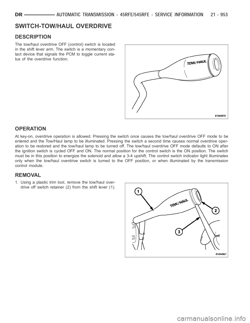
The tow/haul overdrive OFF (control) switch is located
in the shift lever arm. The switch is a momentary con-
tact device that signals the PCM to toggle current sta-
tus of the overdrive function.
OPERATION
At key-on, overdrive operation is allowed. Pressing the switch once causes the tow/haul overdrive OFF mode to be
entered and the Tow/Haul lamp to be illuminated. Pressing the switch a second time causes normal overdrive oper-
ationtoberestoredandthetow/haullamptobeturnedoff.Thetow/hauloverdrive OFF mode defaults to ON after
the ignition switch is cycled OFF and ON. The normal position for the control switch is the ON position. The switch
must be in this position to energize the solenoid and allow a 3-4 upshift. The control switch indicator light illuminates
only when the tow/haul overdrive switch is turned to the OFF position, or when illuminated by the transmission
control module.
REMOVAL
1. Using a plastic trim tool, remove the tow/haul over-
drive off switch retainer (2) from the shift lever (1).
Page 3553 of 5267
Theory of Operation
The Tow/haul Overdrive OFF (control) Switch is located in the shift lever arm. The switch is a momentary contact
device that signals the PCM to toggle current status of the overdrive function. At ignition on, overdrive operation is
allowed. Pressing the Tow/Haul Overdrive Off switch once causes the Tow/haul Overdrive OFF mode to be entered
and the Tow/Haul lamp to be illuminated. Pressing the switch a second time causes normal overdrive operation to
be restored and the Tow/haul lamp to be turned off. The Tow/haul Overdrive OFF mode defaults to ON after the
ignition switch is cycled OFF and ON. Thenormal position for the control switch is the ON position. The switch must
be in this position to energize the solenoid and allow a 3-4 upshift. The control switch indicator light illuminates only
when the Tow/haul Overdrive Off switch is turned to the OFF position, or when illuminated by the transmission con-
trol module.
When Monitored:
The engine must have been running for at minimum of 10 seconds. The circuit is tested every 440ms.
Set Condition:
This DTC will set if the Tow/Haul Overdrive Off Switch Sense circuit is heldlow for 5 minutes or more from the
time of switch closure or ignition on with the engine running.
Possible Causes
TOW/HAUL OVERDRIVE OFF SWITCH SENSE CIRCUIT SHORT TO GROUND
TOW/HAUL OVERDRIVE OFF SWITCH
ENGINE CONTROL MODULE
Always perform the Pre-Diagnostic Troubleshooting procedure before proceeding. (Refer to 21 - TRANSMIS-
SION/TRANSAXLE/AUTOMATIC - 48RE - STANDARD PROCEDURE)
Diagnostic Test
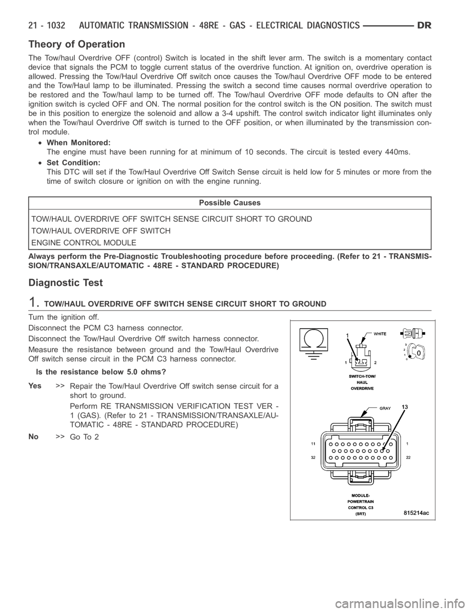
1.TOW/HAUL OVERDRIVE OFF SWITCH SENSE CIRCUIT SHORT TO GROUND
Turn the ignition off.
Disconnect the PCM C3 harness connector.
Disconnect the Tow/Haul OverdriveOff switch harness connector.
Measure the resistance between ground and the Tow/Haul Overdrive
Off switch sense circuit in the PCM C3 harness connector.
Is the resistance below 5.0 ohms?
Ye s>>
Repair the Tow/Haul Overdrive Off switch sense circuit for a
short to ground.
Perform RE TRANSMISSION VERIFICATION TEST VER -
1 (GAS). (Refer to 21 - TRANSMISSION/TRANSAXLE/AU-
TOMATIC - 48RE - STANDARD PROCEDURE)
No>>
Go To 2
Page 3621 of 5267
Theory of Operation
The Transmission Control Output supplies power to the TCC, Overdrive, andGovernor Pressure Solenoids when in
normal operating mode. The Transmission Control Output Control circuit is constantly monitored by the PCM. If the
expected state of the Transmission Control Output Control circuit is different then the expected state, a correspond-
ing DTC will set and the PCM will de-energize the Transmission Control Output and place the transmission in Limp-
in.
When Monitored:
Continuously with the Ignition on.
Set Condition:
This DTC will set if the PCM monitored voltage of the Transmission Control Output Control circuit is different
than the expected voltage for the period 3.0 seconds.
Possible Causes
(T515) TRANSMISSION CONTROL CIRCUIT OPEN
(T515) TRANSMISSION CONTROL CIRCUIT SHORT TO VOLTAGE
(T515) TRANSMISSION CONTROL CIRCUIT SHORT TO GROUND
TOTALLY INTEGRATED POWER MODULE
POWERTRAIN CONTROL MODULE
Always perform the Pre-Diagnostic Troubleshooting procedure before proceeding. (Refer to 21 - TRANSMIS-
SION/TRANSAXLE/AUTOMATIC - 48RE - STANDARD PROCEDURE)
1.CHECK IF THE DTC IS CURRENT
Ignition on, engine not running.
With the scan tool, read Engine DTCs.
Record the Freeze Frame data for the reported DTC.
With the scan tool, erase DTCs.
Turn the ignition off to the lock position.
Using the Freeze Frame data recorded earlier, try to duplicate the conditions in which the DTC originally set.
NOTE: It may be necessary to road test the vehicle to duplicate the originalset conditions.
With the scan tool, read Engine DTCs.
Did the DTC reset?
Ye s>>
Go To 2
No>>
Go To 6
2.CHECK THE (T515) TRANSMISSION CONTROL CIRCUIT
Turn the ignition off to the lock position.
Disconnect the TIPM C1 harness connector.
Ignition on, engine not running.
Using the scan tool in the PCM, actuate the Transmission.
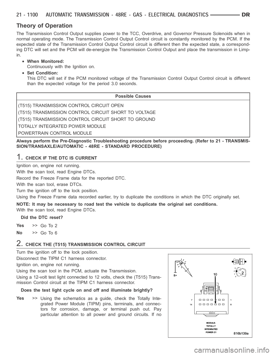
Using a 12-volt test light connected to 12 volts, check the (T515) Trans-
mission Control circuit at the TIPM C1 harness connector.
Does the test light cycle on and off and illuminate brightly?
Ye s>>
Using the schematics as a guide, check the Totally Inte-
grated Power Module (TIPM) pins, terminals, and connec-
tors for corrosion, damage, or terminal push out. Pay
particular attention to all power and ground circuits. If no
Page 3677 of 5267
Theory of Operation
The Transmission Control Output from the Totally Integrated Power Module(TIPM) supplies power to the TCC,
Overdrive, and Governor Pressure Solenoids when in normal operating mode. The Transmission Control circuit is
constantly monitored by the ECM. If the expected state of the TransmissionControl circuit is different then the
expected state, a corresponding DTC will set and the ECM will de-energize the Transmission Control and place the
transmission in Limp-in.
When Monitored:
Continuously with the Ignition on.
Set Condition:
This DTC will set if the ECM monitored voltage of the Transmission Control Relay Control circuit is different
than the expected voltage for the period 3.0 seconds.
Possible Causes
(T515) TRANSMISSION CONTROL CIRCUIT OPEN
(T515) TRANSMISSION CONTROL CIRCUIT SHORT TO GROUND
(T515) TRANSMISSION CONTROL CIRCUIT SHORT TO ANOTHER CIRCUIT
TOTALLY INTEGRATED POWER MODULE (TIPM)
ENGINE CONTROL MODULE
Always perform the Pre-Diagnostic Troubleshooting procedure before proceeding. (Refer to 21 - TRANSMIS-
SION/TRANSAXLE/AUTOMATIC - 48RE - STANDARD PROCEDURE)
1.CHECK IF THE DTC IS CURRENT
Ignition on, engine not running.
With the scan tool, read Engine DTCs.
Record the Freeze Frame data for the reported DTC.
With the scan tool, erase DTCs.
Turn the ignition off to the lock position.
Using the Freeze Frame data recorded earlier, try to duplicate the conditions in which the DTC originally set.
NOTE: It may be necessary to road test the vehicle to duplicate the originalset conditions.
With the scan tool, read Engine DTCs.
Did the DTC reset?
Ye s>>
Go To 2
No>>
Go To 5
2.CHECK THE TIPM FOR CODES
Ignition on, engine not running.
With the scan tool, read TIPM DTCs.
Are there any TIPM DTCs?
Ye s>>
Refer to the Transmission category and perform the appropriate symptom(s).
No>>
Go To 3
Page 3681 of 5267
Theory of Operation
The Transmission Control Output from the Totally Integrated Power Module(TIPM) supplies power to the TCC,
Overdrive, and Governor Pressure Solenoids when in normal operating mode. The Transmission Control circuit is
constantly monitored by the ECM. If the expected state of the TransmissionControl circuit is different then the
expected state, a corresponding DTC will set and the ECM will de-energize the Transmission Control and place the
transmission in Limp-in.
When Monitored:
Continuously with the ignition on.
Set Condition:
This DTC will set if the ECM monitored voltage of the Transmission Control circuit is different than the
expected voltage for the period 3.0 seconds.
Possible Causes
(T515) TRANSMISSION CONTROL CIRCUIT SHORT TO VOLTAGE
(T515) TRANSMISSION CONTROL CIRCUIT SHORT TO ANOTHER CIRCUIT
ENGINE CONTROL MODULE
Always perform the Pre-Diagnostic Troubleshooting procedure before proceeding. (Refer to 21 - TRANSMIS-
SION/TRANSAXLE/AUTOMATIC - 48RE - STANDARD PROCEDURE)
Diagnostic Test
1.CHECK IF THE DTC IS CURRENT
Ignition on, engine not running.
With the scan tool, read Engine DTCs.
Record the Freeze Frame data for the reported DTC.
With the scan tool, erase DTCs.
Turn the ignition off to the lock position.
Using the Freeze Frame data recorded earlier, try to duplicate the conditions in which the DTC originally set.
NOTE: It may be necessary to road test the vehicle to duplicate the originalset conditions.
With the scan tool, read Engine DTCs.
Did the DTC reset?
Ye s>>
Go To 2
No>>
Go To 5
2.CHECK THE TIPM FOR CODES
Ignition on, engine not running.
With the scan tool, read TIPM DTCs.
Are there any TIPM DTCs?
Ye s>>
Refer to the Transmission category and perform the appropriate symptom(s).
No>>
Go To 3