Page 4046 of 5267
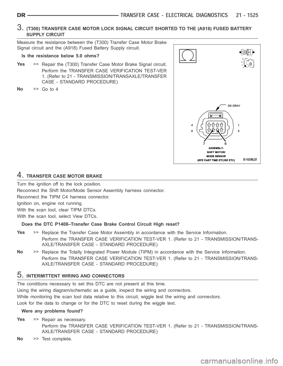
3.(T300) TRANSFER CASE MOTOR LOCK SIGNAL CIRCUIT SHORTED TO THE (A918) FUSEDBATTERY
SUPPLY CIRCUIT
Measure the resistance between the (T300) Transfer Case Motor Brake
Signal circuit and the (A918) Fused Battery Supply circuit.
Is the resistance below 5.0 ohms?
Ye s>>
Repair the (T300) Transfer Case Motor Brake Signal circuit.
Perform the TRANSFER CASE VERIFICATION TEST-VER
1. (Refer to 21 - TRANSMISSION/TRANSAXLE/TRANSFER
CASE - STANDARD PROCEDURE)
No>>
Go to 4
4.TRANSFER CASE MOTOR BRAKE
Turn the ignition off to the lock position.
Reconnect the Shift Motor/Mode Sensor Assembly harness connector.
Reconnect the TIPM C4 harness connector.
Ignition on, engine not running.
With the scan tool, clear TIPM DTCs.
With the scan tool, select View DTCs.
Does the DTC P1408–Transfer Case Brake Control Circuit High reset?
Ye s>>
Replace the Transfer Case Motor Assembly in accordance with the Service Information.
Perform the TRANSFER CASE VERIFICATION TEST-VER 1. (Refer to 21 - TRANSMISSION/TRANS-
AXLE/TRANSFER CASE - STANDARD PROCEDURE)
No>>
Replace the Totally Integrated Power Module (TIPM) in accordance with theService Information.
Perform the TRANSFER CASE VERIFICATION TEST-VER 1. (Refer to 21 - TRANSMISSION/TRANS-
AXLE/TRANSFER CASE - STANDARD PROCEDURE)
5.INTERMITTENT WIRING AND CONNECTORS
The conditions necessary to set this DTC are not present at this time.
Using the wiring diagram/schematic as a guide, inspect the wiring and connectors.
While monitoring the scan tool data relative to this circuit, wiggle test the wiring and connectors.
Look for the data to change or for the DTC to reset during the wiggle test.
Were any problems found?
Ye s>>
Repair as necessary.
Perform the TRANSFER CASE VERIFICATION TEST-VER 1. (Refer to 21 - TRANSMISSION/TRANS-
AXLE/TRANSFER CASE - STANDARD PROCEDURE)
No>>
Te s t c o m p l e t e .
Page 4048 of 5267
When Monitored:
Ignition on. Battery voltage between 9.0 and 16.0 volts.
Set Condition:
Totally Integrated Power Module (TIPM) detects low voltage on the Transfer Case Motor Control circuit for a
period of 0.5 seconds.
Possible Causes
(T101) SHIFT MOTOR CONTROL A CIRCUIT SHORTED TO GROUND
(T102) SHIFT MOTOR CONTROL B CIRCUIT SHORTED TO GROUND
(T101) SHIFT MOTOR CONTROL A CIRCUIT SHORTED TO THE (T102) SHIFT MOTOR CONTROL B CIRCUIT
SHIFT MOTOR/MODE SENSOR ASSEMBLY
TOTALLY INTEGRATED POWER MODULE (TIPM)
Diagnostic Test
1.DTC IS ACTIVE
Ignition on, engine not running.
With the scan tool, read TIPM DTCs.
Is the status Active for this DTC?
Ye s>>
Go to 2
No>>
Go to 9
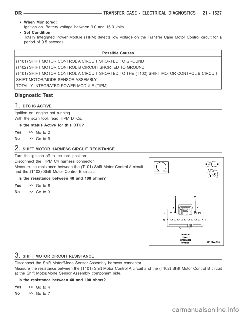
2.SHIFT MOTOR HARNESS CIRCUIT RESISTANCE
Turn the ignition off to the lock position.
Disconnect the TIPM C4 harness connector.
Measure the resistance between the (T101) Shift Motor Control A circuit
and the (T102) Shift Motor Control B circuit.
Is the resistance between 40 and 100 ohms?
Ye s>>
Go to 8
No>>
Go to 3
3.SHIFT MOTOR CIRCUIT RESISTANCE
Disconnect the Shift Motor/Mode Sensor Assembly harness connector.
Measure the resistance between the (T101) Shift Motor Control A circuit and the (T102) Shift Motor Control B circuit
at the Shift Motor/Mode Sensor Assembly component side.
Is the resistance between 40 and 100 ohms?
Ye s>>
Go to 4
No>>
Go to 7
Page 4053 of 5267
When Monitored:
Ignition on, battery voltage between 9.0 and 16.0 volts.
Set Condition:
The TIPM detects 16.0 to 18.0 volts on the Transfer Case Motor Control Circuit for 2 seconds.
Possible Causes
(T101) SHIFT MOTOR CONTROL A CIRCUIT SHORTED TO VOLTAGE
(T102) SHIFT MOTOR CONTROL BCIRCUIT SHORTED TO VOLTAGE
(T101) SHIFT MOTOR CONTROL A CIRCUIT SHORTED TO (T102) SHIFT MOTOR CONTROLB CIRCUIT
SHIFT MOTOR/MODE SENSOR ASSEMBLY
TOTALLY INTEGRATED POWER MODULE (TIPM)
Diagnostic Test
1.DTC IS ACTIVE
Ignition on, engine not running.
With the scan tool, read TIPM DTCs.
Is the status Active for this DTC?
Ye s>>
Go to 2
No>>
Go to 9
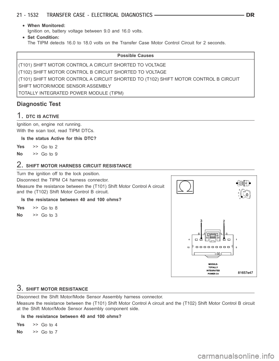
2.SHIFT MOTOR HARNESS CIRCUIT RESISTANCE
Turn the ignition off to the lock position.
Disconnect the TIPM C4 harness connector.
Measure the resistance between the (T101) Shift Motor Control A circuit
and the (T102) Shift Motor Control B circuit.
Is the resistance between 40 and 100 ohms?
Ye s>>
Go to 8
No>>
Go to 3
3.SHIFT MOTOR RESISTANCE
Disconnect the Shift Motor/Mode Sensor Assembly harness connector.
Measure the resistance between the (T101) Shift Motor Control A circuit and the (T102) Shift Motor Control B circuit
at the Shift Motor/Mode Sensor Assembly component side.
Is the resistance between 40 and 100 ohms?
Ye s>>
Go to 4
No>>
Go to 7
Page 4058 of 5267
When Monitored:
Ignition on, battery voltage between 9.0 and 16.0 volts.
Set Condition:
The TIPM detects no voltage on the Transfer Case Motor Control circuit for aperiod greater than 2 seconds,
when voltage should be present.
Possible Causes
(T101) SHIFT MOTOR CONTROL A CIRCUIT OPEN
(T102) SHIFT MOTOR CONTROL B CIRCUIT OPEN
SHIFT MOTOR/MODE SENSOR ASSEMBLY
TOTALLY INTEGRATED POWER MODULE (TIPM)
Diagnostic Test
1.DTC IS ACTIVE
Ignition on, engine not running.
With the scan tool, read TIPM DTCs.
Move the Shift control to each position, while monitoring the Data Displayon the scan tool.
Does the DTC reset?
Ye s>>
Go to 2
No>>
Go to 8
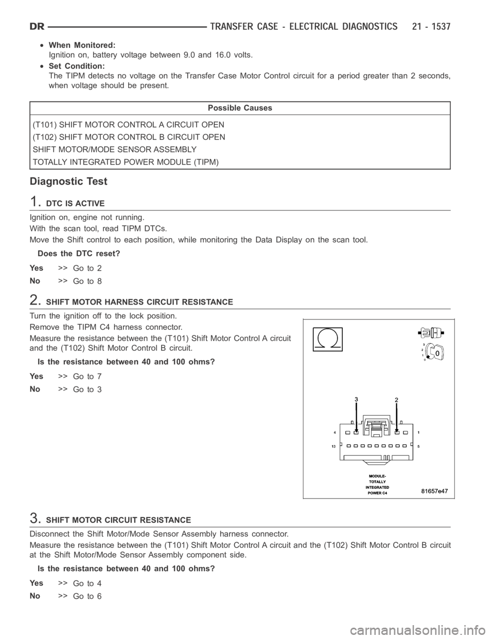
2.SHIFT MOTOR HARNESS CIRCUIT RESISTANCE
Turn the ignition off to the lock position.
Remove the TIPM C4 harness connector.
Measure the resistance between the (T101) Shift Motor Control A circuit
and the (T102) Shift Motor Control B circuit.
Is the resistance between 40 and 100 ohms?
Ye s>>
Go to 7
No>>
Go to 3
3.SHIFT MOTOR CIRCUIT RESISTANCE
Disconnect the Shift Motor/Mode Sensor Assembly harness connector.
Measure the resistance between the (T101) Shift Motor Control A circuit and the (T102) Shift Motor Control B circuit
at the Shift Motor/Mode Sensor Assembly component side.
Is the resistance between 40 and 100 ohms?
Ye s>>
Go to 4
No>>
Go to 6
Page 4083 of 5267
TRANSFER CASE VERIFICATION TEST
1.
Disconnect all jumper wires and reconnect all previously disconnected components and connectors.
With the scan tool, select clear Stored DTCs.
Make sure that all accessories are turned off and that the battery is fully charged.
Test drive the vehicle in each Transfer Case range and verify proper operation in each range.
To select or deselect 2WD, AWD or 4HI mode, vehicle speed must be below 88 Kmh(55 mph) with all wheels
at vehicle speed.
Shifts will not take place with a wheel speed difference of greater than 21 Kmh (13 mph) between the front
and rear wheels.
To select or deselect 4LO (if equipped), vehicle speed must be below 5 Kmh (3mph) with the ignition ON and
the transmission in neutral (auto trans) or the clutch pedal pressed (man trans).
To select or deselect Transfer Case Neutral, vehicle speed must be 0 Kmh (0 mph) with the ignition ON,
engine OFF, the brake pedal applied, and the transmission in neutral (autotrans) or the clutch pedal pressed
(man trans). Press the Neutral button (if equipped) on the Transfer Case Selector Switch until the Neutral Indi-
cator is illuminated.
WARNING: Apply the parking brake. The vehicle may roll with the Transfer Case in neutral.
To verify that the Transfer Case is in Neutral, shift the automatic transmission into reverse and release the
brake pedal for three seconds or shift the manual transmission into gear andslowlyreleasetheclutchpedal.
There should be no vehicle movement if the Transfer Case is in Neutral.
With the scan tool, select View DTCs in the Totally Integrated Power Module(TIPM) and in the Instrument Cluster.
Are there any DTCs present in the Totally Integrated Power Module (TIPM) orin the Instrument Cluster?
Ye s>>
Return to the symptom list and perform the appropriate diagnostic test.
No>>
Repair is complete.
Page 4101 of 5267
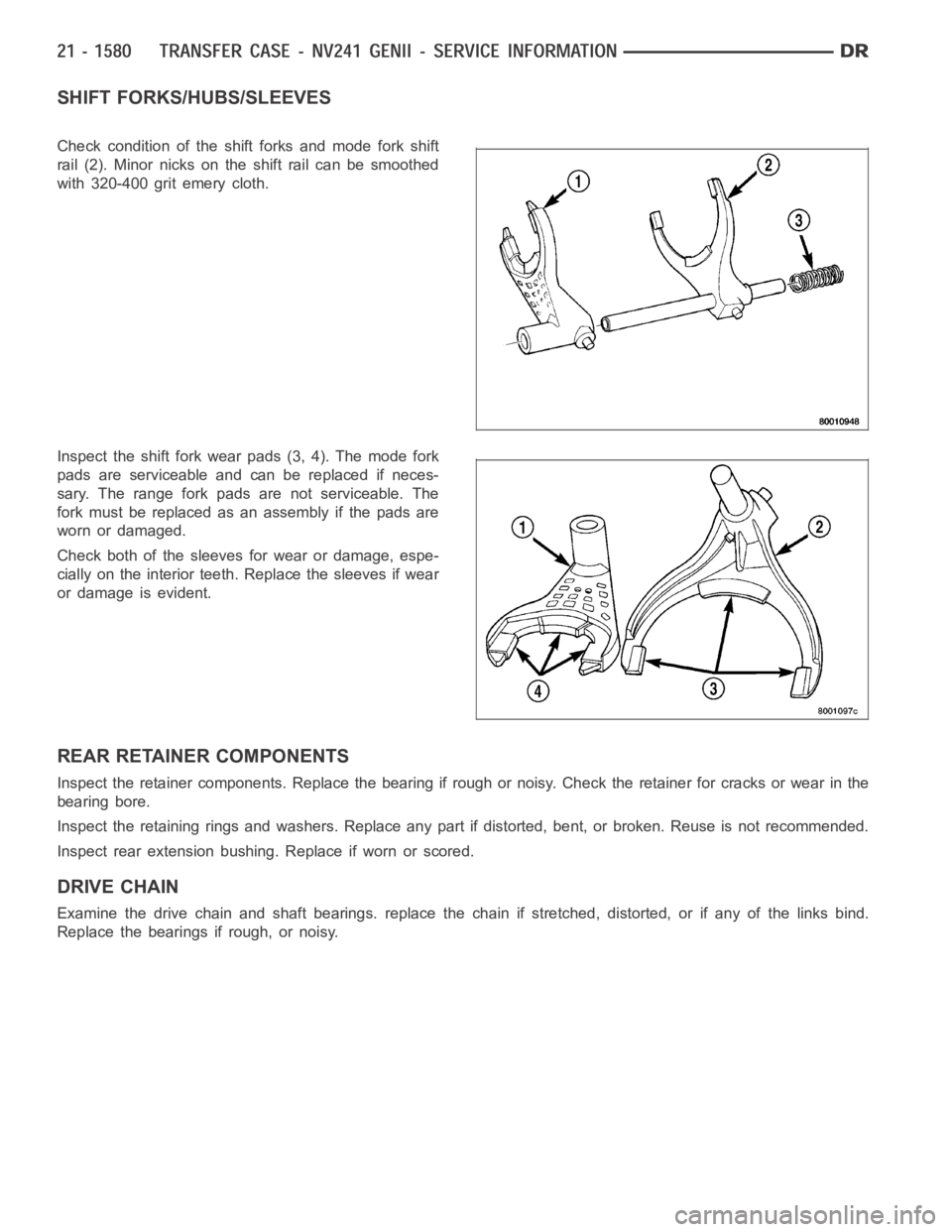
SHIFT FORKS/HUBS/SLEEVES
Check condition of the shift forks and mode fork shift
rail (2). Minor nicks on the shift rail can be smoothed
with 320-400 grit emery cloth.
Inspect the shift fork wear pads (3, 4). The mode fork
pads are serviceable and can be replaced if neces-
sary. The range fork pads are not serviceable. The
fork must be replaced as an assembly if the pads are
worn or damaged.
Check both of the sleeves for wear or damage, espe-
cially on the interior teeth. Replace the sleeves if wear
or damage is evident.
REAR RETAINER COMPONENTS
Inspect the retainer components. Replace the bearing if rough or noisy. Check the retainer for cracks or wear in the
bearing bore.
Inspect the retaining rings and washers. Replace any part if distorted, bent, or broken. Reuse is not recommended.
Inspect rear extension bushing. Replace if worn or scored.
DRIVE CHAIN
Examine the drive chain and shaft bearings. replace the chain if stretched, distorted, or if any of the links bind.
Replace the bearings if rough, or noisy.
Page 4107 of 5267
SHIFT FORKS AND MAINSHAFT
1. Lubricate mainshaft splines with recommended
transmission fluid.
2. Install the mode hub (1) onto the output shaft.
3. Install the mode hub retaining ring (2) onto the out-
put shaft (1).
4. Install the sprocket hub (2) onto the output shaft
(1).
Page 4155 of 5267
SHIFT FORKS AND MAINSHAFT
1. Lubricate mainshaft splines with recommended
transmission fluid.
2. Coat the interior of the drive sprocket hub with
ATF+4 and install the drive sprocket drive hub (2)
onto the mainshaft (1).
3. Install the mode hub (2) onto the mainshaft (1).