2006 DODGE RAM SRT-10 ECO mode
[x] Cancel search: ECO modePage 5160 of 5267

FAN-A/C CONDENSER
DESCRIPTION
All models equipped with gasoline engines, except
SRT 8, use an electric cooling fan to help pull heat out
of the A/C system, especially during idle conditions.
Without a cooling fan, A/C high side pressures would
increase and A/C system performance would eventu-
ally deteriorate.
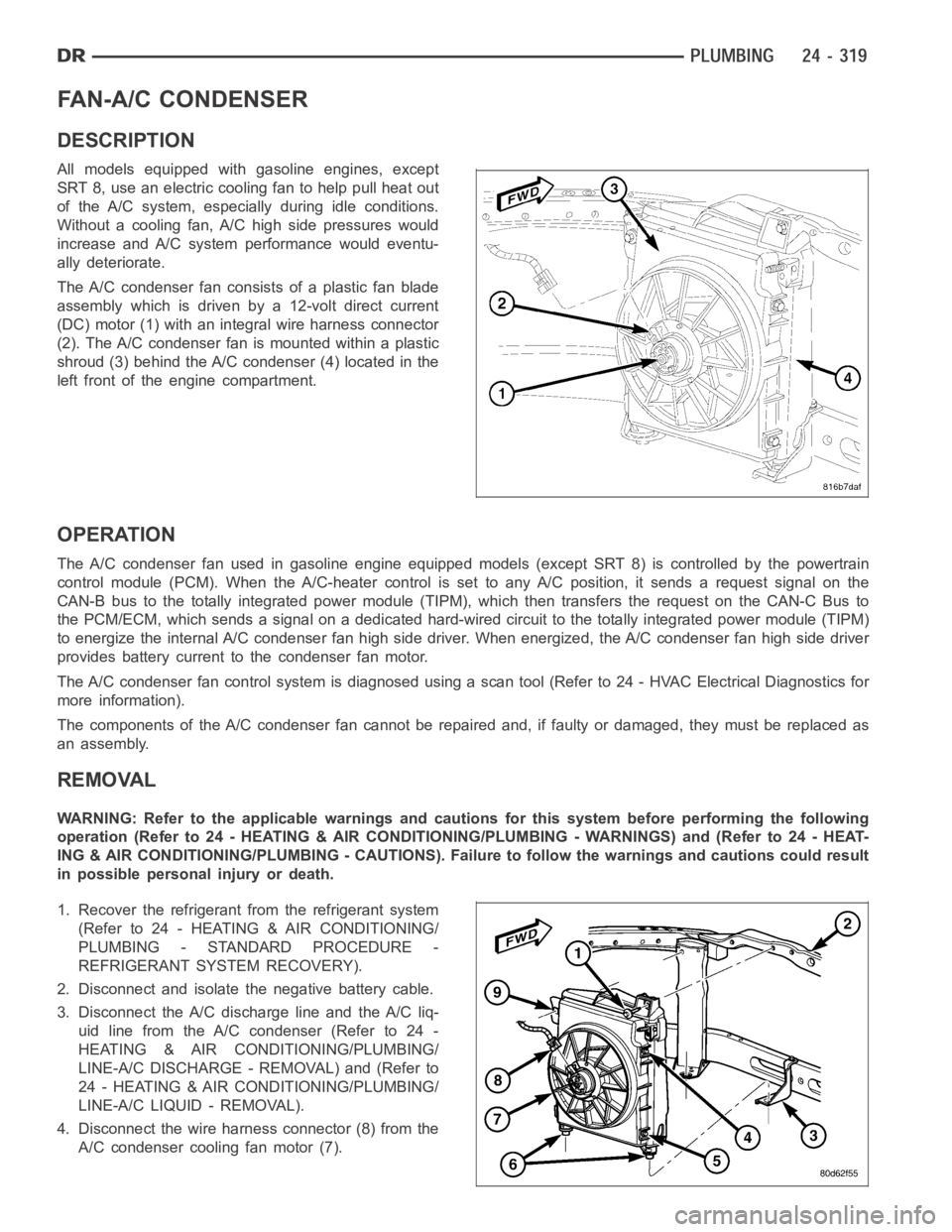
The A/C condenser fan consists of a plastic fan blade
assembly which is driven by a 12-volt direct current
(DC) motor (1) with an integral wire harness connector
(2). The A/C condenser fan is mounted within a plastic
shroud (3) behind the A/C condenser (4) located in the
left front of the engine compartment.
OPERATION
The A/C condenser fan used in gasoline engine equipped models (except SRT 8) is controlled by the powertrain
control module (PCM). When the A/C-heater control is set to any A/C position, it sends a request signal on the
CAN-B bus to the totally integrated power module (TIPM), which then transfers the request on the CAN-C Bus to
the PCM/ECM, which sends a signal on a dedicated hard-wired circuit to the totally integrated power module (TIPM)
to energize the internal A/C condenser fan high side driver. When energized, the A/C condenser fan high side driver
provides battery current to the condenser fan motor.
The A/C condenser fan control system isdiagnosed using a scan tool (Refer to 24 - HVAC Electrical Diagnostics for
more information).
The components of the A/C condenser fan cannot be repaired and, if faulty ordamaged, they must be replaced as
an assembly.
REMOVAL
WARNING: Refer to the applicable warnings and cautions for this system before performing the following
operation (Refer to 24 - HEATING & AIR CONDITIONING/PLUMBING - WARNINGS) and (Refer to 24 - HEAT-
ING & AIR CONDITIONING/PLUMBING - CAUTIONS). Failure to follow the warnings and cautions could result
in possible personal injury or death.
1. Recover the refrigerant from the refrigerant system
(Refer to 24 - HEATING & AIR CONDITIONING/
PLUMBING - STANDARD PROCEDURE -
REFRIGERANT SYSTEM RECOVERY).
2. Disconnect and isolate the negative battery cable.
3. Disconnect the A/C discharge line and the A/C liq-
uidlinefromtheA/Ccondenser(Referto24-
HEATING & AIR CONDITIONING/PLUMBING/
LINE-A/C DISCHARGE - REMOVAL) and (Refer to
24 - HEATING & AIR CONDITIONING/PLUMBING/
LINE-A/C LIQUID - REMOVAL).
4. Disconnect the wire harness connector (8) from the
A/C condenser cooling fan motor (7).
Page 5171 of 5267

LINE-A/C LIQUID
DESCRIPTION
The liquid line is the refrigerant line that carries refrigerant from the A/C condenser to the A/C evaporator. The liquid
line for this model consist of two separate lines that connect to each otherusing a spring-lock type refrigerant line
coupler (Refer to 24 - HEATING & AIR CONDITIONING/PLUMBING/REFRIGERANT LINE COUPLER - DESCRIP-
TION). The liquid lines are made from light-weight aluminum, and use braze-less fittings.
The front half of the liquid line includes the high-side service port and the rear half of the liquid line contains the
fixed orifice tube.
CAUTION: Use only O-ring seals specified for the vehicle. Failure to use the correct O-ring seal will cause
the refrigerant system connections to leak.
The liquid line has no serviceable parts except for the rubber O-ring seals, high-side service port valve, cap and
secondary retaining clip. The O-ring seals used on the connections are made from a special type of rubber not
affected by R-134a refrigerant. The O-ring seals must be replaced whenever the liquid line is removed and installed.
If the liquid line is found to be leaking or is damaged, it must be replaced.
REMOVAL
3.7L/4.7L/5.7L/5.9L ENGINES
WARNING: Refer to the applicable warnings and cautions for this system before performing the following
operation (Refer to 24 - HEATING & AIR CONDITIONING/PLUMBING - WARNINGS) and (Refer to 24 - HEAT-
ING & AIR CONDITIONING/PLUMBING - CAUTIONS). Failure to follow the warnings and cautions could result
in possible personal injury or death.
NOTE:TheA/Cliquidlineisservicedintwosections.
FRONT SECTION
1. Recover the refrigerant from the refrigerant system
(Refer to 24 - HEATING & AIR CONDITIONING/
PLUMBING - STANDARD PROCEDURE -
REFRIGERANT SYSTEM RECOVERY).
2. Disconnect and isolate the negative battery cable.
3. If equipped with the diesel engine, remove the pas-
senger side battery (Refer to 8 - ELECTRICAL/
BATTERY SYSTEM/BATTERY - REMOVAL).
4. If equipped with a gasoline engine, remove the air
filter housing and mounting bracket (Refer to 9 -
ENGINE/AIR INTAKE SYSTEM/AIR FILTER
HOUSING - REMOVAL).
5. Remove the plastic cover from the condenser out-
let stud.
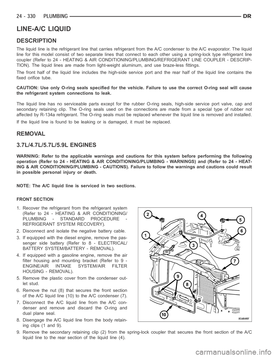
6. Remove the nut (8) that secures the front section
of the A/C liquid line (10) to the A/C condenser (7).
7. Disconnect the A/C liquid line from the A/C con-
denser and remove and discard the O-ring and
dual plane seal.
8. Disengage the A/C liquid line from the body retain-
ing clips (1 and 9).
9. Remove the secondary retaining clip (2) from the spring-lock coupler that secures the front section of the A/C
liquid line to the rear section of the liquid line (4).
Page 5193 of 5267

EMISSIONS CONTROL
DESCRIPTION
STATE DISPLAY TEST MODE
The switch inputs to the Powertrain Control Module (PCM) have two recognized states; HIGH and LOW. For this
reason, the PCM cannot recognize the difference between a selected switchposition versus an open circuit, a short
circuit, or a defective switch. If the State Display screen shows the changefromHIGHtoLOWorLOWtoHIGH,
assume the entire switch circuit to the PCM functions properly. Connect the DRB scan tool to the data link con-
nector and access the state display screen. Then access either State Display Inputs and Outputs or State Display
Sensors.
CIRCUIT ACTUATION TEST MODE
The Circuit Actuation Test Mode checks for proper operation of output circuits or devices the Powertrain Control
Module (PCM) may not internally recognize. The PCM attempts to activate these outputs and allow an observer to
verify proper operation. Most of the tests provide an audible or visual indication of device operation (click of relay
contacts, fuel spray, etc.). Except for intermittent conditions, if a device functions properly during testing, assume the
device, its associated wiring, and driver circuit work correctly. Connect the DRB scan tool to the data link connector
and access the Actuators screen.
DIAGNOSTIC TROUBLE CODES
A Diagnostic Trouble Code (DTC) indicates the PCM has recognized an abnormal condition in the system.
Remember that DTC’s are the results of a system or circuit failure, but do not directly identify the failed
component or components.
BULB CHECK
Each time the ignition key is turned to the ON position, the malfunction indicator (check engine) lamp on the instru-
ment panel should illuminate for approximately 2 seconds then go out. Thisis done for a bulb check.
OBTAINING DTC’S USING DRB SCAN TOOL
1. Obtain the applicable Powertrain Diagnostic Manual.
2. Obtain the DRB Scan Tool.
3. Connect the DRB Scan Tool to the data link (diagnostic) connector. This connector is located in the passenger
compartment at the lower edge of instrument panel, and near the steering column.
4. Turn the ignition switch on and access the “Read Fault” screen.
5. Record all the DTC’s and “freeze frame” information shown on the DRB scantool.
6. To erase DTC’s, use the “Erase Trouble Code” data screen on the DRB scan tool.Do not erase any DTC’s
until problems have been investigated and repairs have been performed.
TA S K M A N A G E R
The PCM is responsible for efficiently coordinating the operation of all the emissions-related components. The PCM
is also responsible for determining if the diagnostic systems are operating properly. The software designed to carry
out these responsibilities is called the ’Task Manager’.
MONITORED SYSTEMS
There are new electronic circuit monitors that check fuel, emission, engine and ignition performance. These moni-
tors use information from various sensor circuits to indicate the overalloperation of the fuel, engine, ignition and
emission systems and thus the emissions performance of the vehicle.
The fuel, engine, ignition and emission systems monitors do not indicate aspecific component problem. They do
indicate that there is an implied problem within one of the systems and thata specific problem must be diagnosed.
If any of these monitors detect a problem affecting vehicle emissions, theMalfunction Indicator Lamp (MIL) will be
illuminated. These monitors generate Diagnostic Trouble Codes that can be displayed with the MIL or a scan tool.
Page 5224 of 5267

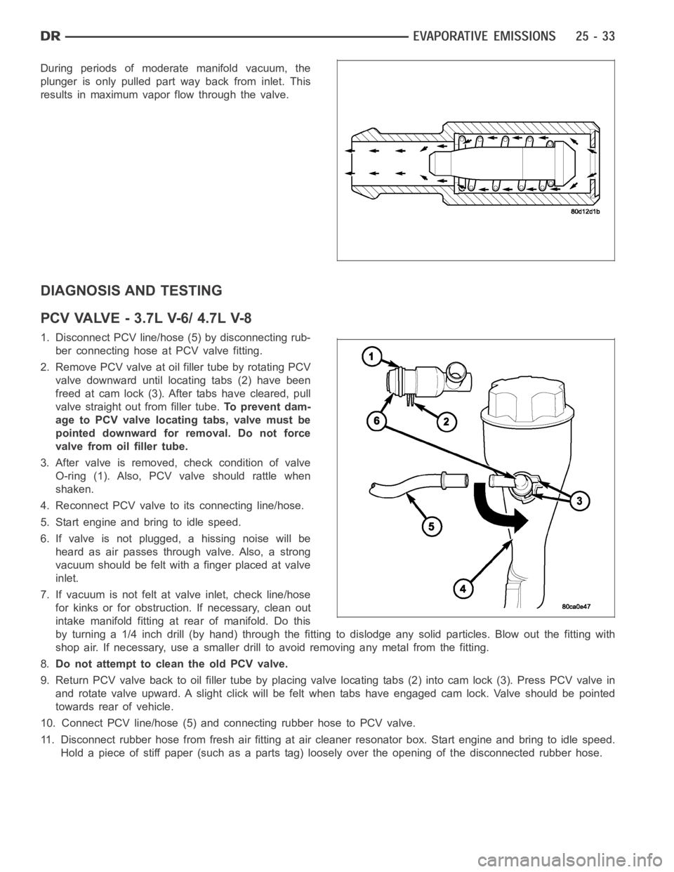
During periods of moderate manifold vacuum, the
plunger is only pulled part way back from inlet. This
results in maximum vapor flow through the valve.
DIAGNOSIS AND TESTING
PCVVALVE-3.7LV-6/4.7LV-8
1. Disconnect PCV line/hose (5) by disconnecting rub-
ber connecting hose at PCV valve fitting.
2. Remove PCV valve at oil filler tube by rotating PCV
valve downward until locating tabs (2) have been
freed at cam lock (3). After tabs have cleared, pull
valve straight out from filler tube.To prevent dam-
age to PCV valve locating tabs, valve must be
pointed downward for removal. Do not force
valve from oil filler tube.
3. After valve is removed, check condition of valve
O-ring (1). Also, PCV valve should rattle when
shaken.
4. Reconnect PCV valve to its connecting line/hose.
5. Start engine and bring to idle speed.
6. If valve is not plugged, a hissing noise will be
heard as air passes through valve. Also, a strong
vacuum should be felt with a finger placed at valve
inlet.
7. If vacuum is not felt at valve inlet, check line/hose
for kinks or for obstruction. If necessary, clean out
intake manifold fitting at rear of manifold. Do this
byturninga1/4inchdrill(byhand)throughthefittingtodislodgeanysolid particles. Blow out the fitting with
shop air. If necessary, use a smaller drill to avoid removing any metal fromthe fitting.
8.Do not attempt to clean the old PCV valve.
9. Return PCV valve back to oil filler tube by placing valve locating tabs (2) into cam lock (3). Press PCV valve in
and rotate valve upward. A slight click will be felt when tabs have engaged cam lock. Valve should be pointed
towards rear of vehicle.
10. Connect PCV line/hose (5) and connecting rubber hose to PCV valve.
11. Disconnect rubber hose from fresh air fitting at air cleaner resonatorbox. Start engine and bring to idle speed.
Hold a piece of stiff paper (such as a parts tag) loosely over the opening of the disconnected rubber hose.