2006 DODGE RAM SRT-10 ECO mode
[x] Cancel search: ECO modePage 4993 of 5267
Theory of Operation
The A/C Heater Control drives the Mode Door 2 (Defrost to Floor) Actuator viathe(C801)ModeDoor2Driver
circuit and the (C34) Common Door Driver circuit. All of the door actuatorsshare the (C34) Common Door Driver
circuit. Inside the A/C Heater Control, each door actuator has its own unique driver, but all share a single common
door driver circuit. Due to the shared circuitry similar DTCs can set at thesame time for multiple actuators depend-
ing upon the type of short, its location, and the direction the actuator is moving when the short is present.
When Monitored:
When the Actuator DTC Detection Test is executed.
Set Condition:
If the (C801) Mode Door 2 Driver circuit is shorted to voltage.
Possible Causes
(C801) MODE DOOR 2 DRIVER CIRCUIT SHORTED TO VOLTAGE
A/C HEATER CONTROL
Diagnostic Test
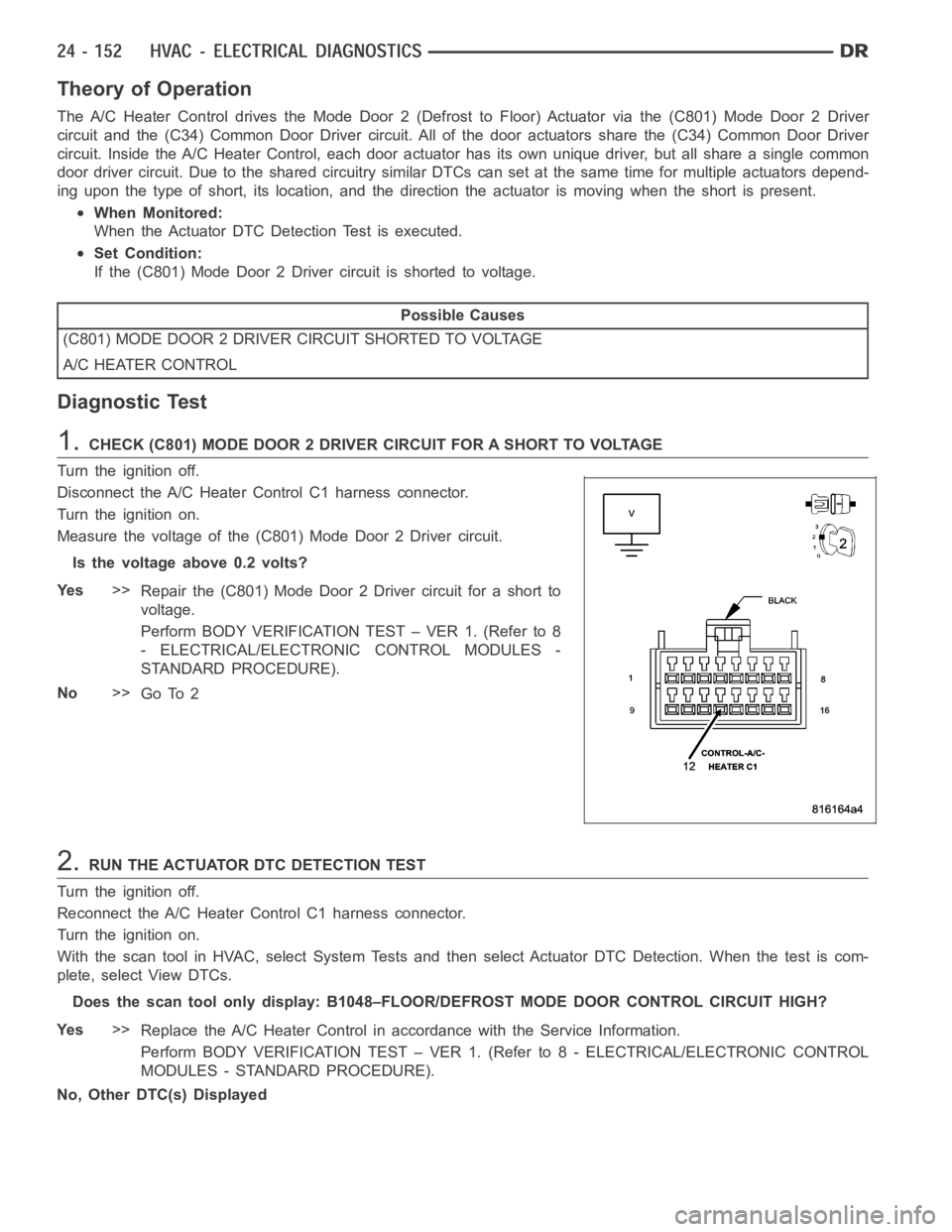
1.CHECK (C801) MODE DOOR 2 DRIVER CIRCUIT FOR A SHORT TO VOLTAGE
Turn the ignition off.
Disconnect the A/C Heater Control C1 harness connector.
Turn the ignition on.
Measure the voltage of the (C801) Mode Door 2 Driver circuit.
Is the voltage above 0.2 volts?
Ye s>>
Repair the (C801) Mode Door 2 Driver circuit for a short to
voltage.
Perform BODY VERIFICATION TEST – VER 1. (Refer to 8
- ELECTRICAL/ELECTRONIC CONTROL MODULES -
STANDARD PROCEDURE).
No>>
Go To 2
2.RUN THE ACTUATOR DTC DETECTION TEST
Turn the ignition off.
Reconnect the A/C Heater Control C1 harness connector.
Turn the ignition on.
With the scan tool in HVAC, select System Tests and then select Actuator DTCDetection. When the test is com-
plete, select View DTCs.
Does the scan tool only display: B1048–FLOOR/DEFROST MODE DOOR CONTROL CIRCUIT HIGH?
Ye s>>
Replace the A/C Heater Control in accordance with the Service Information.
Perform BODY VERIFICATION TEST – VER 1. (Refer to 8 - ELECTRICAL/ELECTRONIC CONTROL
MODULES - STANDARD PROCEDURE).
No, Other DTC(s) Displayed
Page 4996 of 5267
Theory of Operation
The A/C Heater Control drives the Mode Door 2 (Defrost to Floor) Actuator viathe(C801)ModeDoor2Driver
circuit and the (C34) Common Door Driver circuit. All of the door actuatorsshare the (C34) Common Door Driver
circuit. Inside the A/C Heater Control, each door actuator has its own unique driver, but all share a single common
door driver circuit. Due to the shared circuitry similar DTCs can set at thesame time for multiple actuators depend-
ing upon the location of the open circuit and the direction the actuator is moving when the open is present.
When Monitored:
During actuator calibration.
Set Condition:
If the Mode Door 2 (Defrost to Floor) Actuator’s electrical circuit is open. This DTC has a maturing time of 5
seconds and a de-maturing time of 10 seconds. If the DTC’s status changes from active to stored it will stay
in memory for 100 ignition cycles.
Possible Causes
(C801) MODE DOOR 2 DRIVER CIRCUIT OPEN
(C34) COMMON DOOR DRIVER CIRCUIT OPEN
MODE DOOR 2 (DEFROST TO FLOOR) ACTUATOR
A/C HEATER CONTROL
NOTE: This DTC must be active for the results of this test to be valid. Do not perform this test if this DTC
is stored. Refer to HVAC System Test for stored DTC test procedures.
Diagnostic Test
1.CHECK FOR ACTIVE CONTROL CIRCUIT/PERFORMANCE DTCs
Turn the ignition on.
With the scan tool, read active HVAC DTCs.
Does the scan tool display any active: XXXX CONTROL CIRCUIT/PERFORMANCE DTCs?
Ye s>>
Diagnose and repair the DTC(s). Refer to the Table of Contents in this Section for a complete list of
HVAC related symptoms.
No>>
Go To 2
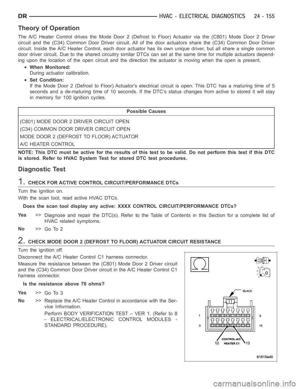
2.CHECK MODE DOOR 2 (DEFROST TO FLOOR) ACTUATOR CIRCUIT RESISTANCE
Turn the ignition off.
Disconnect the A/C Heater Control C1 harness connector.
Measure the resistance between the (C801) Mode Door 2 Driver circuit
and the (C34) Common Door Driver circuit in the A/C Heater Control C1
harness connector.
Is the resistance above 70 ohms?
Ye s>>
Go To 3
No>>
Replace the A/C Heater Control in accordance with the Ser-
vice Information.
Perform BODY VERIFICATION TEST – VER 1. (Refer to 8
- ELECTRICAL/ELECTRONIC CONTROL MODULES -
STANDARD PROCEDURE).
Page 4999 of 5267
Theory of Operation
The A/C Heater Control drives the Mode Door 2 (Defrost to Floor) Actuator viathe(C801)ModeDoor2Driver
circuit and the (C34) Common Door Driver circuit. All of the door actuatorsshare the (C34) Common Door Driver
circuit. Inside the A/C Heater Control, each door actuator has its own unique driver, but all share a single common
door driver circuit. Due to the shared circuitry similar DTCs can set at thesame time for multiple actuators depend-
ing upon the location of the open circuit and the direction the actuator is moving when the open is present.
When Monitored:
During actuator calibration.
Set Condition:
If the Mode Door 2 (Defrost to Floor) Actuator’s electrical circuit is open. This DTC has a maturing time of 5
seconds and a de-maturing time of 10 seconds. If the DTC’s status changes from active to stored it will stay
in memory for 100 ignition cycles.
Possible Causes
(C801) MODE DOOR 2 DRIVER CIRCUIT OPEN
(C34) COMMON DOOR DRIVER CIRCUIT OPEN
MODE DOOR 2 (DEFROST TO FLOOR) ACTUATOR
A/C HEATER CONTROL
NOTE: This DTC must be active for the results of this test to be valid. Do not perform this test if this DTC
is stored. Refer to HVAC System Test for stored DTC test procedures.
Diagnostic Test
1.CHECK FOR ACTIVE CONTROL CIRCUIT/PERFORMANCE DTCs
Turn the ignition on.
With the scan tool, read active HVAC DTCs.
Does the scan tool display any active: XXXX CONTROL CIRCUIT/PERFORMANCE DTCs?
Ye s>>
Diagnose and repair the DTC(s). Refer to the Table of Contents in this Section for a complete list of
HVAC related symptoms.
No>>
Go To 2
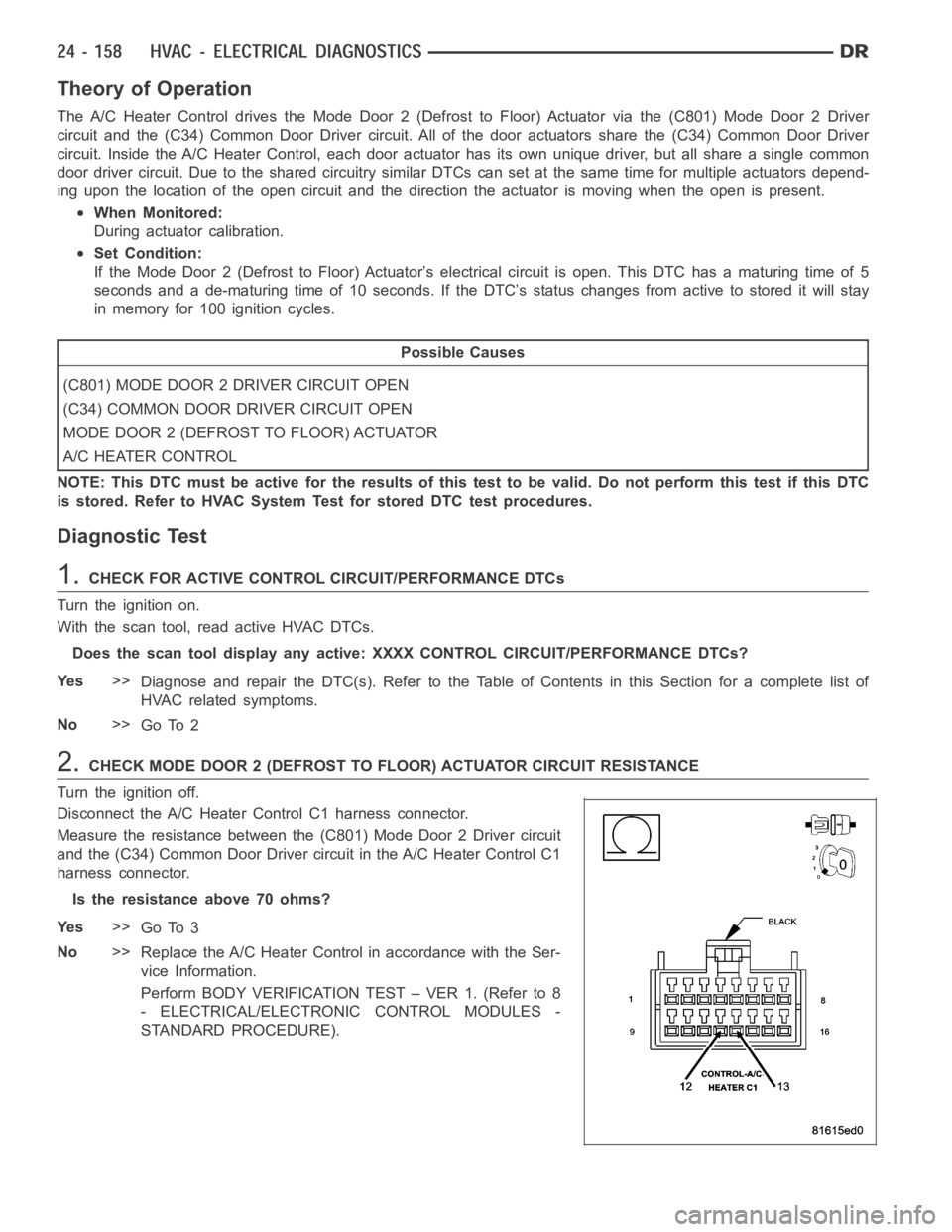
2.CHECK MODE DOOR 2 (DEFROST TO FLOOR) ACTUATOR CIRCUIT RESISTANCE
Turn the ignition off.
Disconnect the A/C Heater Control C1 harness connector.
Measure the resistance between the (C801) Mode Door 2 Driver circuit
and the (C34) Common Door Driver circuit in the A/C Heater Control C1
harness connector.
Is the resistance above 70 ohms?
Ye s>>
Go To 3
No>>
Replace the A/C Heater Control in accordance with the Ser-
vice Information.
Perform BODY VERIFICATION TEST – VER 1. (Refer to 8
- ELECTRICAL/ELECTRONIC CONTROL MODULES -
STANDARD PROCEDURE).
Page 5023 of 5267
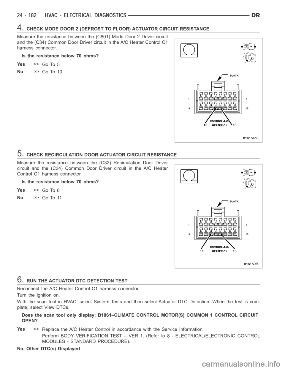
4.CHECK MODE DOOR 2 (DEFROST TO FLOOR) ACTUATOR CIRCUIT RESISTANCE
Measure the resistance between the (C801) Mode Door 2 Driver circuit
and the (C34) Common Door Driver circuit in the A/C Heater Control C1
harness connector.
Is the resistance below 70 ohms?
Ye s>>
Go To 5
No>>
Go To 10
5.CHECK RECIRCULATION DOOR ACTUATOR CIRCUIT RESISTANCE
Measure the resistance between the (C32) Recirculation Door Driver
circuit and the (C34) Common Door Driver circuit in the A/C Heater
Control C1 harness connector.
Is the resistance below 70 ohms?
Ye s>>
Go To 6
No>>
Go To 11
6.RUN THE ACTUATOR DTC DETECTION TEST
Reconnect the A/C Heater Control C1 harness connector.
Turn the ignition on.
With the scan tool in HVAC, select System Tests and then select Actuator DTCDetection. When the test is com-
plete, select View DTCs.
Does the scan tool only display: B1061–CLIMATE CONTROL MOTOR(S) COMMON 1 CONTROL CIRCUIT
OPEN?
Ye s>>
Replace the A/C Heater Control in accordance with the Service Information.
Perform BODY VERIFICATION TEST – VER 1. (Refer to 8 - ELECTRICAL/ELECTRONIC CONTROL
MODULES - STANDARD PROCEDURE).
No, Other DTC(s) Displayed
Page 5047 of 5267

With the scan tool in HVAC, select System Tests and then select Cooldown test. Allow the test to run to completion.
Does the scan tool display a status message that indicates a fault has occurred?
Yes, Conditions Too Cold - Test Not Run
If running, turn the A/C compressor off. Verify that the work area ambient temperature is above 15.6°C
(60°F). If not, move the vehicle to a warmer work area. Verify that the evaporator temperature is above
13°C (55°F). If not, set the blower to high speed and allow the blower to run for five minutes. Then, run
the Cooldown Test again.
Yes, Blowers Not On High - Test Not Run
Set the blower speed to high speed and then run the Cooldown Test again.
Yes, No Results Stored/Test Not Complete
Verify that power is not interrupted while rerunning the Cooldown Test.
Yes, Refrigerant Temperature Sensor Error
For Dual-Zone HVAC systems, refer to B10B2–A/C COOL DOWN TEST PERFORMANCEfor the diag-
nostic test procedure. For Single-Zone HVAC systems, refer to B1079–CLIMATE CONTROL COOL
DOWN TEST EXCESSIVE TIME for the diagnostic test procedure.
Yes, DTC Set During Routine - Test Not Passed
For Dual-Zone HVAC systems, refer to B10B2–A/C COOL DOWN TEST PERFORMANCEfor the diag-
nostic test procedure. For Single-Zone HVAC systems, refer to B1079–CLIMATE CONTROL COOL
DOWN TEST EXCESSIVE TIME for the diagnostic test procedure.
No>>
Asnecessary,eitherGoTo3,4,or5,or Perform BODY VERIFICATION TEST - VER1. (Refer to 8 -
ELECTRICAL/ELECTRONIC CONTROL MODULES - STANDARD PROCEDURE).
3.MODE SWITCH & DOOR ACTUATOR CIRCUIT TEST
NOTE: If at anytime a DTC becomes active during this test, proceed to the conclusion question.
NOTE: If multiple DTCs are active, diagnose those that relate to a short circuit first.
NOTE: Dual-Zone A/C Heater Controls do not set DTCs for stuck mode switches. Therefore, verify that the
A/C Heater Control is not damaged and that the mode switches and status indicators function properly and
repair as necessary before proceeding.
If not done so previously, start the engine.
Turn the Blower control to the low speed position.
Set the Blend control (single-zone) or Driver Blend control (dual-zone) to the full cold position.
If equipped, set the Passenger Blend control to the full cold position.
Monitor the scan tool for active HVAC DTCs while performing the following test steps.
If equipped, press the A/C mode switch on, wait 30 seconds, and then press itoff.
On Dual-Zone systems, press the Recirc mode switch on, wait 30 seconds, andthen press it off.
If equipped, press the EBL mode switch on, wait 30 seconds, and then press itoff.
Move the Blend control (single-zone) or Driver Blend control (dual-zone)from full cold to full hot, wait 30 seconds,
and then move it back to full cold.
If equipped, move the Passenger Blend control from full cold to full hot, wait 30 seconds, and then moved it back
to full cold.
Turn the Mode select control to the defrost position, wait 30 seconds, and then turn it to the panel position (dual-
zone) or panel / recirc position (single-zone). Wait 30 seconds before proceeding.
Does the scan tool display any active DTCs?
Ye s>>
Diagnose and repair the DTC(s). Refer to the Table of Contents in this Section for a complete list of
HVAC related symptoms.
No>>
If you are here due to a stored DTC, it is possible that a technician may not have erased the DTC
following a repair. If possible, verify if the vehicle was recently in for this type of service. Otherwise,
either Go To 4 or 5, or visually inspect the related wiring harness for chafed, pierced, pinched, and
partially broken wires and the wiring harness connectors for broken, bent, pushed out, and corroded
terminals, and repair as necessary.
Perform BODY VERIFICATION TEST - VER 1. (Refer to 8 - ELECTRICAL/ELECTRONIC CONTROL
MODULES - STANDARD PROCEDURE).
Page 5050 of 5267
HVAC - SERVICE INFORMATION
DESCRIPTION
A manually controlled single zone type heating-air conditioning system or a manually controlleddualzonetypeheat-
ing-air conditioning system is available on this model.
To maintain the performance level of the heating, ventilation and air conditioning (HVAC) system, the engine cooling
system must be properly maintained. The use of a bug screen is not recommended. Any obstructions in front of the
radiator or A/C condenser will reduce the performance of the A/C and enginecooling systems.
The engine cooling system includes the radiator, thermostat, radiator hoses and the engine coolant pump. Refer to
7 - Cooling for more information before opening or attempting any service to the engine cooling system.
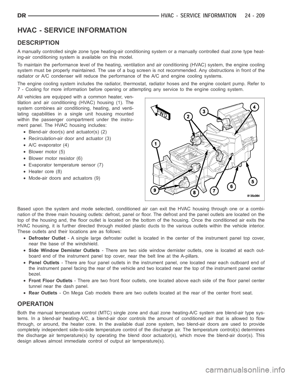
All vehicles are equipped with a common heater, ven-
tilation and air conditioning (HVAC) housing (1). The
system combines air conditioning, heating, and venti-
lating capabilities in a single unit housing mounted
within the passenger compartment under the instru-
ment panel. The HVAC housing includes:
Blend-air door(s) and actuator(s) (2)
Recirculation-air door and actuator (3)
A/C evaporator (4)
Blower motor (5)
Blower motor resistor (6)
Evaporator temperature sensor (7)
Heater core (8)
Mode-air doors and actuators (9)
Based upon the system and mode selected, conditioned air can exit the HVAC housing through one or a combi-
nation of the three main housing outlets: defrost, panel or floor. The defrost and the panel outlets are located on the
top of the housing and, the floor outlet is located on the bottom of the housing. Once the conditioned air exits the
HVAC housing, it is further directed through molded plastic ducts to the various outlets within the vehicle interior.
These outlets and their locations are as follows:
Defroster Outlet- A single large defroster outlet is located in the center of the instrumentpanel top cover,
near the base of the windshield.
Side Window Demister Outlets- There are two side window demister outlets, one is located at each out-
board end of the instrument panel top cover, near the belt line at the A-pillars.
Panel Outlets- There are four panel outlets in the instrument panel, one located near each outboard end of
the instrument panel facing the rear of the vehicle and two located near thetop of the instrument panel center
bezel.
Front Floor Outlets- There are two front floor outlets, one located above each side of the floorpanel center
tunnel near the dash panel.
Rear Outlets- On Mega Cab models there are two outlets located at the rear of the center front seat.
OPERATION
Both the manual temperature control (MTC) single zone and dual zone heating-A/C system are blend-air type sys-
tems. In a blend-air heating-A/C, a blend-air door controls the amount of conditioned air that is allowed to flow
through, or around, the heater core.In the available dual zone system, twoblend-air doors are used to provide
completely independent side-to-side temperature control of the discharge air. The temperature control(s) determines
the discharge air temperature(s) by operating the blend door actuator(s), which move the blend-air door(s). This
design allows almost immediate control of output air temperature(s).
Page 5052 of 5267
DIAGNOSIS AND TESTING
HEATING-A/C SYSTEM DIAGNOSTICS
CAUTION: Do not exchange A/C Heater Controls from vehicle to vehicle. Software versions differ between
models and model years. Installing an A/C Heater Control with software that is incompatible for a given
vehicle can result in either improper or failed HVAC system operation.
ON-BOARD DIAGNOSTICS
The A/C-heater control communicates on the controller area network (CAN)B bus and is fully addressable with a
scan tool.
The A/C-heater control’s primary means of fault detection is through active and stored diagnostic trouble codes
(DTCs). Active DTCs are those which currently exist in the system. The condition causing the fault must be repaired
in order to clear this type of DTC. Stored DTCs are those which occurred in the system since the A/C-heater control
received the last clear diagnostic info message. DTCs must be read with a scan tool. Refer to 24 - HVAC - Elec-
trical Diagnostics for HVAC DTC diagnostic test procedures.
The A/C-heater control’s secondary means of fault detection is through system tests. These tests include the HVAC
System Test, the A/C Cooldown Test, Actuator Calibration, and Actuator DTC Detection. Refer to System Tests in
this Section for a detailed description of each test.
SYSTEM TESTS
HVAC System Test
The HVAC System Test, found in 24 - HVAC - Electrical Diagnostics, providesa starting point in the diagnostic
process by identifying the appropriate diagnostic procedure or system test to perform when diagnosing a given
symptom, condition, or DTC. It also provides a means for testing the entireHVAC system by utilizing the A/C-heater
control’s On-Board System Tests. The On-Board System Tests can also assistindiagnosingstoredDTCs.
A/CCOOLDOWNTEST
The A/C Cooldown Test:
is actuated with a scan tool.
tests A/C system performance based on evaporator temperature sensor input.
will fail if evaporator temperature isbelow 13°C (55°F) when initiating the test.
will pass if the evaporator temperature drops 11°C (20°F).
indicates an outcome by displaying one or more test status messages on the scan tool. These test status
messages will clear after paging back out of this test function. Therefore, is it important to note all of the mes-
sages before doing so.
will cause the A/C status indicator to flash while the test is running.
ACTUATOR CALIBRATION FUNCTION
The Actuator Calibration function:
is actuated with a scan tool.
clears all actuator related DTCs when the test is actuated.
homes and repositions door actuators.
monitors for door span faults. Door span faults (XXX Door Travel Range Too Large or XXX Door Travel Range
Too Small) will only display after calibration.
will cause the electric backlight (EBL) status indicator (if equipped) toflash while the test is running.
Page 5056 of 5267
Condition Possible Causes Correction
5. Engine overheating.5. Refer to Cooling for more information. Test the
cooling system and repair, if required.
The low side pressure is too
high, and the high side
pressure is too low.1. Accessory drive belt
slipping.1. Refer to Cooling for more information. Inspect
the accessory drive belt condition and tension.
Tighten or replace the accessory drive belt, if
required.
2. Fixed orifice tube not
installed.2. See A/C Orifice Tube in this group. Replace the
liquid line, if required.
3. Faulty A/C compressor.3. See A/C Compressor in this group. Replace the
compressor, if required.
The low side pressure is too
low, and the high side
pressure is too high.1. Restricted refrigerant flow
through the refrigerant lines.1. See Liquid, Suction, and Discharge Line in this
group. Inspect the refrigerant lines for kinks, tight
bends or improper routing. Correct the routing or
replace the refrigerant line, if required.
2. Restricted refrigerant flow
through the fixed orifice
tube.2. See A/C Orifice Tube in this group. Replace the
liquid line, if required.
3. Restricted refrigerant flow
through the condenser.3. See A/C Condenser in this group. Replace the
restricted condenser, if required.
HEATER PERFORMANCE
Before performing the following tests, refer to Group 7 - Cooling for the procedures to check the engine coolant
level and flow, engine coolant reserve/recovery system operation, accessory drive belt condition and tension, radi-
ator air flow and the fan drive operation. Perform the HVAC System Test (refer to 24 - HVAC Electrical Diagnostics).
If any diagnostic trouble codes (DTCs) are found in the A/C-heater control, powertrain control module (PCM) or
engine control module (ECM) (depending on engine application), gateway module or totally integrated power module
(TIPM), repair as necessary.
MAXIMUM HEATER OUTPUT: TEST AND ACTION
Engine coolant is provided to the heater system through two heater hoses. With the engine idling at normal oper-
ating temperature, set the temperature control to maximum heat position,the mode control to the floor position, and
the blower motor control to the highest speed position. Using a test thermometer, check the temperature of the air
being discharged from the floor outlets. Compare the test thermometer reading to the Heater Temperature Refer-
ence chart.
HEATER TEMPERATURE REFERENCE
Ambient Air Temperature16° C
(60° F)21° C
(70° F)26° C
(80° F)32° C
(90° F)
Minimum Air Temperature at
Floor Outlet62° C
(144° F)64° C
(147° F)65° C
(150° F)67° C
(153° F)
If the heater outlet air temperature is below the minimum specification, refer to Group 7 - Cooling. Both of the heater
hoses should be hot to the touch. The coolant return heater hose should be slightly cooler than the coolant supply
heater hose. If the return hose is much cooler than the supply hose, locate and repair the engine coolant flow
obstruction in the cooling system. RefertoGroup7-Coolingformoreinformation.
OBSTRUCTED COOLANT FLOW
Possible locations or causes of obstructed coolant flow are as follows:
Faulty water pump.
Faulty thermostat.
Pinched or kinked heater hoses.