Page 4199 of 5267
7. Install snap-ring (2) to hold input/low range gear (1)
into front bearing.
8. Install a new input gear seal using Installer 8841
and Universal Handle C-4171.
SHIFT FORKS AND MAINSHAFT
1. Lubricate mainshaft splines with recommended
transmission fluid.
2. Install the mode hub (2) onto the output shaft (1).
3. Install the mode hub retaining ring (2) onto the out-
put shaft (1).
Page 4214 of 5267

SENSOR-MODE
DESCRIPTION
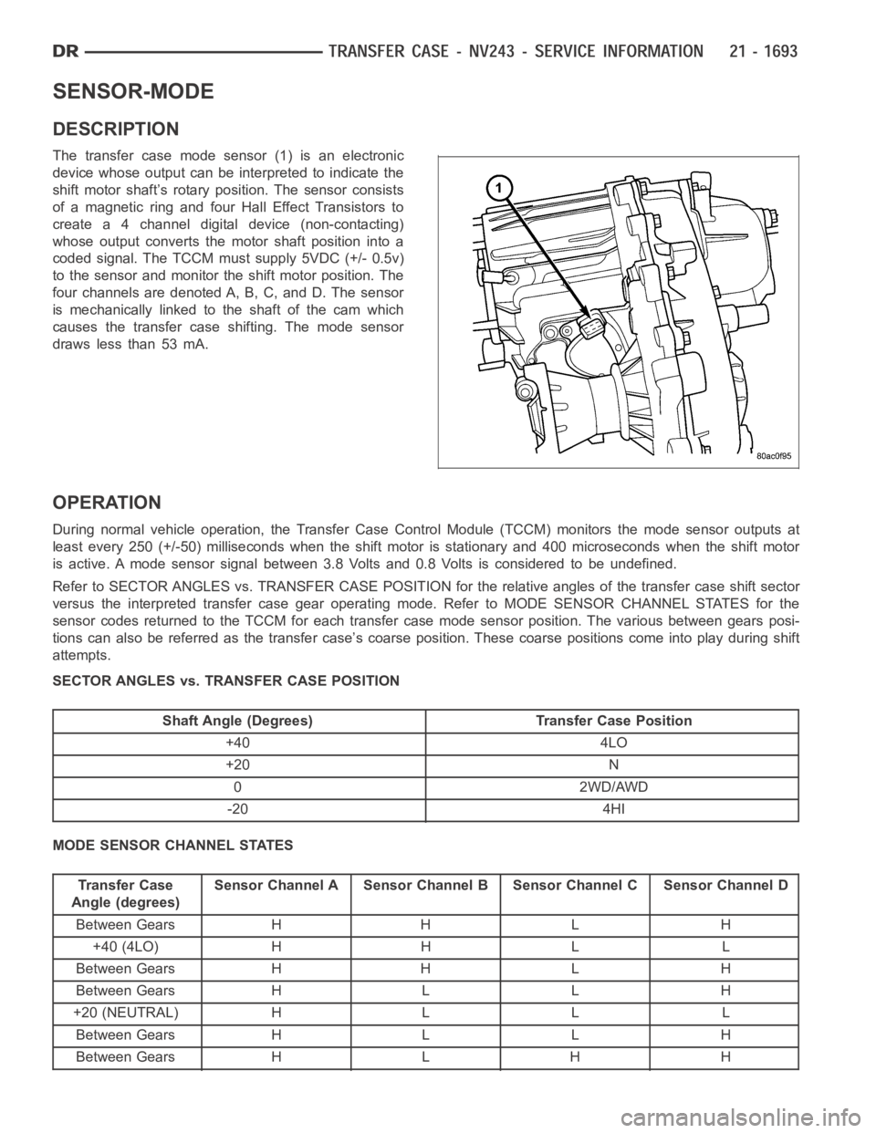
The transfer case mode sensor (1) is an electronic
device whose output can be interpreted to indicate the
shift motor shaft’s rotary position. The sensor consists
of a magnetic ring and four Hall Effect Transistors to
create a 4 channel digital device (non-contacting)
whose output converts the motor shaft position into a
coded signal. The TCCM must supply 5VDC (+/- 0.5v)
to the sensor and monitor the shift motor position. The
four channels are denoted A, B, C, and D. The sensor
is mechanically linked to the shaft of the cam which
causes the transfer case shifting. The mode sensor
draws less than 53 mA.
OPERATION
During normal vehicle operation, the Transfer Case Control Module (TCCM)monitors the mode sensor outputs at
least every 250 (+/-50) milliseconds when the shift motor is stationary and 400 microseconds when the shift motor
is active. A mode sensor signal between 3.8 Volts and 0.8 Volts is considered to be undefined.
Refer to SECTOR ANGLES vs. TRANSFER CASE POSITION for the relative angles of the transfer case shift sector
versus the interpreted transfer case gear operating mode. Refer to MODE SENSOR CHANNEL STATES for the
sensor codes returned to the TCCM for each transfer case mode sensor position. The various between gears posi-
tions can also be referred as the transfer case’s coarse position. These coarse positions come into play during shift
attempts.
SECTOR ANGLES vs. TRANSFER CASE POSITION
Shaft Angle (Degrees) Transfer Case Position
+40 4LO
+20 N
0 2WD/AWD
-20 4HI
MODE SENSOR CHANNEL STATES
Transfer Case
Angle (degrees)Sensor Channel A Sensor Channel B Sensor Channel C Sensor Channel D
Between Gears H H L H
+40 (4LO) H H L L
Between Gears H H L H
Between Gears H L L H
+20 (NEUTRAL) H L L L
Between Gears H L L H
Between Gears H L H H
Page 4242 of 5267
SHIFT FORKS AND MAINSHAFT
1. Lubricate mainshaft splines with recommended
transmission fluid.
NOTE: Replace the mode hub retainer if the legs
were distorted during removal.
2. Install the mode hub retainer (1) onto the mode
hub (2).
3. Install the mode hub (2) and mode hub retainer
onto the differential assembly (1). Make sure the
retainer is fully seated onto the differential.
4. Install the differential assembly (1) onto the main-
shaft (2).
Page 4258 of 5267

SENSOR-MODE
DESCRIPTION
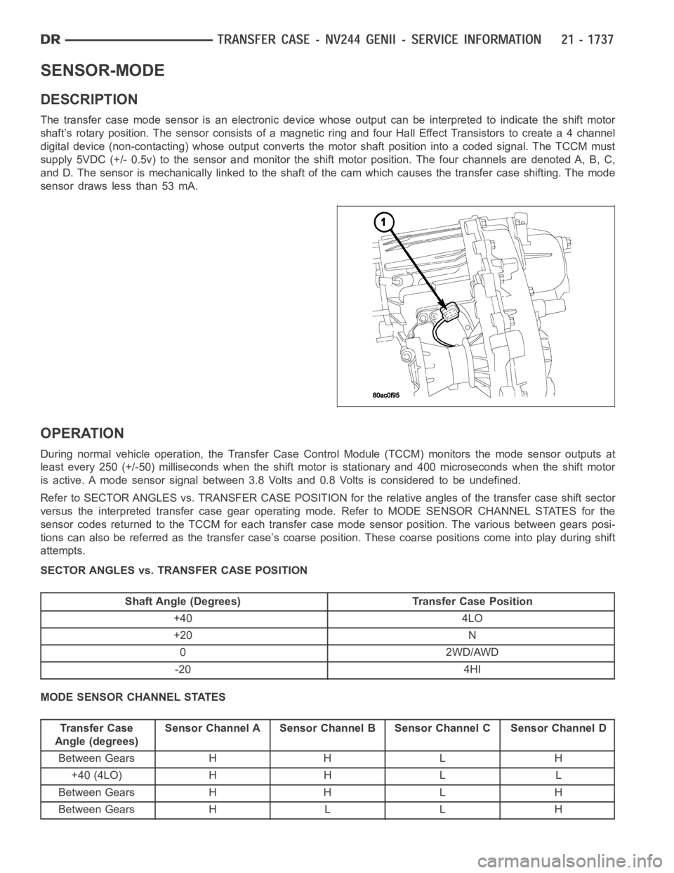
The transfer case mode sensor is an electronic device whose output can be interpreted to indicate the shift motor
shaft’s rotary position. The sensor consists of a magnetic ring and four Hall Effect Transistors to create a 4 channel
digital device (non-contacting) whose output converts the motor shaft position into a coded signal. The TCCM must
supply 5VDC (+/- 0.5v) to the sensor and monitor the shift motor position. The four channels are denoted A, B, C,
and D. The sensor is mechanically linked to the shaft of the cam which causesthe transfer case shifting. The mode
sensor draws less than 53 mA.
OPERATION
During normal vehicle operation, the Transfer Case Control Module (TCCM)monitors the mode sensor outputs at
least every 250 (+/-50) milliseconds when the shift motor is stationary and 400 microseconds when the shift motor
is active. A mode sensor signal between 3.8 Volts and 0.8 Volts is considered to be undefined.
Refer to SECTOR ANGLES vs. TRANSFER CASE POSITION for the relative angles of the transfer case shift sector
versus the interpreted transfer case gear operating mode. Refer to MODE SENSOR CHANNEL STATES for the
sensor codes returned to the TCCM for each transfer case mode sensor position. The various between gears posi-
tions can also be referred as the transfer case’s coarse position. These coarse positions come into play during shift
attempts.
SECTOR ANGLES vs. TRANSFER CASE POSITION
Shaft Angle (Degrees) Transfer Case Position
+40 4LO
+20 N
0 2WD/AWD
-20 4HI
MODE SENSOR CHANNEL STATES
Transfer Case
Angle (degrees)Sensor Channel A Sensor Channel B Sensor Channel C Sensor Channel D
Between Gears H H L H
+40 (4LO) H H L L
Between Gears H H L H
Between Gears H L L H
Page 4292 of 5267
SHIFT FORKS AND MAINSHAFT
1. Lubricate mainshaft splines with recommended
transmission fluid.
2. Coat the interior of the drive sprocket hub with
ATF+4 and install the drive sprocket drive hub (2)
onto the mainshaft (1).
3. Install the mode hub (2) onto the mainshaft (1).
Page 4308 of 5267

SENSOR-MODE
DESCRIPTION
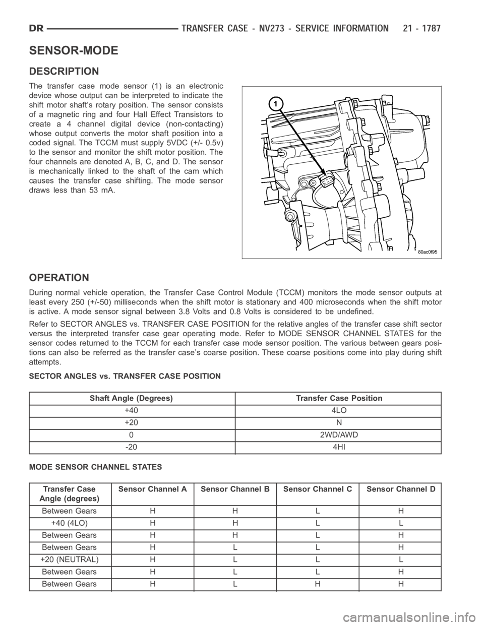
The transfer case mode sensor (1) is an electronic
device whose output can be interpreted to indicate the
shift motor shaft’s rotary position. The sensor consists
of a magnetic ring and four Hall Effect Transistors to
create a 4 channel digital device (non-contacting)
whose output converts the motor shaft position into a
coded signal. The TCCM must supply 5VDC (+/- 0.5v)
to the sensor and monitor the shift motor position. The
four channels are denoted A, B, C, and D. The sensor
is mechanically linked to the shaft of the cam which
causes the transfer case shifting. The mode sensor
draws less than 53 mA.
OPERATION
During normal vehicle operation, the Transfer Case Control Module (TCCM)monitors the mode sensor outputs at
least every 250 (+/-50) milliseconds when the shift motor is stationary and 400 microseconds when the shift motor
is active. A mode sensor signal between 3.8 Volts and 0.8 Volts is considered to be undefined.
Refer to SECTOR ANGLES vs. TRANSFER CASE POSITION for the relative angles of the transfer case shift sector
versus the interpreted transfer case gear operating mode. Refer to MODE SENSOR CHANNEL STATES for the
sensor codes returned to the TCCM for each transfer case mode sensor position. The various between gears posi-
tions can also be referred as the transfer case’s coarse position. These coarse positions come into play during shift
attempts.
SECTOR ANGLES vs. TRANSFER CASE POSITION
Shaft Angle (Degrees) Transfer Case Position
+40 4LO
+20 N
0 2WD/AWD
-20 4HI
MODE SENSOR CHANNEL STATES
Transfer Case
Angle (degrees)Sensor Channel A Sensor Channel B Sensor Channel C Sensor Channel D
Between Gears H H L H
+40 (4LO) H H L L
Between Gears H H L H
Between Gears H L L H
+20 (NEUTRAL) H L L L
Between Gears H L L H
Between Gears H L H H
Page 4329 of 5267

WHEEL DESIGN
The rim size is on the vehicle safety certification label
located on the drivers door shut face. The size of the
rim is determined by the drivetrain package. Original
equipment wheels/rims are designed for operation up
to the specified maximum vehicle capacity.
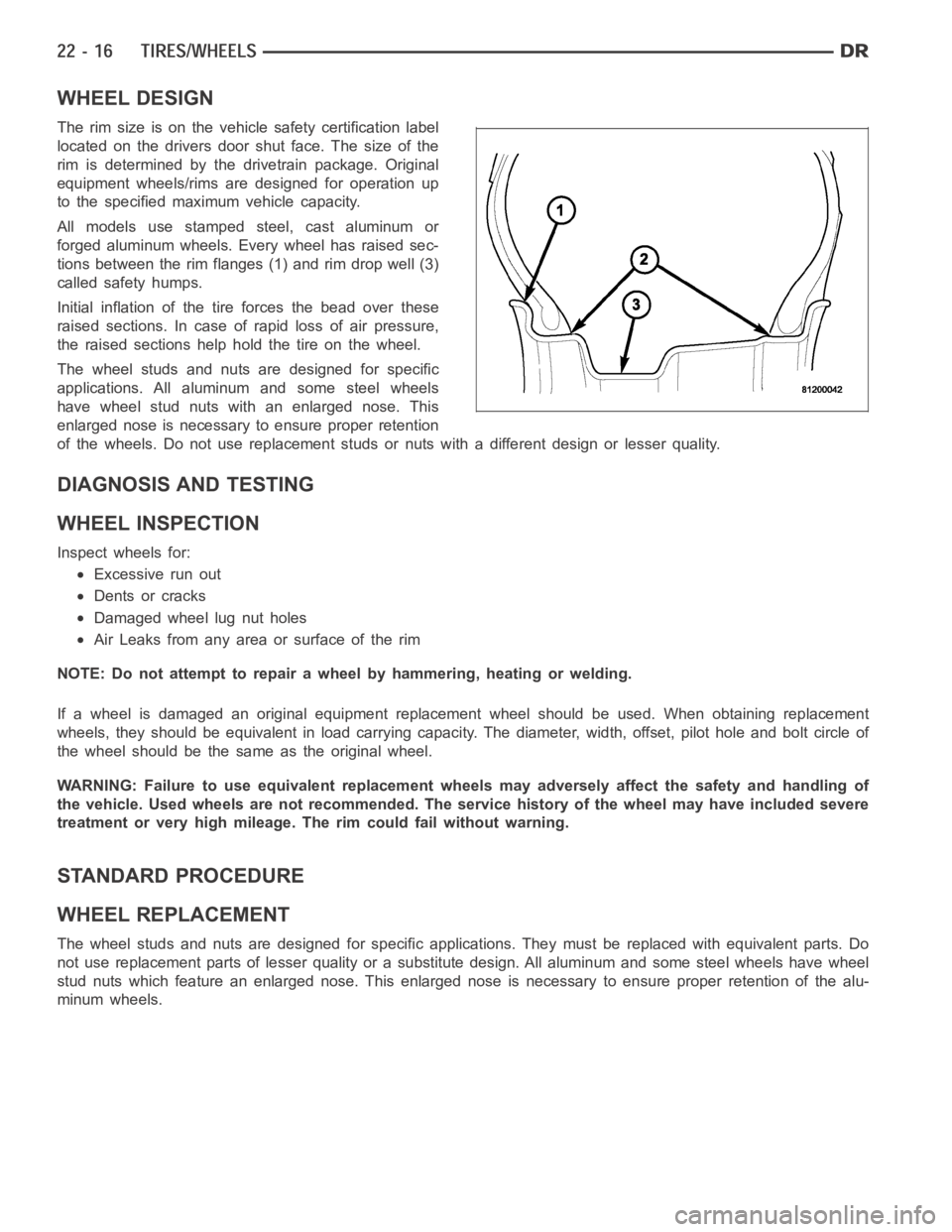
All models use stamped steel, cast aluminum or
forged aluminum wheels. Every wheel has raised sec-
tions between the rim flanges (1) and rim drop well (3)
called safety humps.
Initial inflation of the tire forces the bead over these
raised sections. In case of rapid loss of air pressure,
the raised sections help hold the tire on the wheel.
The wheel studs and nuts are designed for specific
applications. All aluminum and some steel wheels
have wheel stud nuts with an enlarged nose. This
enlarged nose is necessary to ensure proper retention
of the wheels. Do not use replacement studs or nuts with a different design orlesserquality.
DIAGNOSIS AND TESTING
WHEEL INSPECTION
Inspect wheels for:
Excessive run out
Dents or cracks
Damaged wheel lug nut holes
Air Leaks from any area or surface of the rim
NOTE: Do not attempt to repair a wheel by hammering, heating or welding.
If a wheel is damaged an original equipment replacement wheel should be used. When obtaining replacement
wheels, they should be equivalent in load carrying capacity. The diameter, width, offset, pilot hole and bolt circle of
the wheel should be the same as the original wheel.
WARNING: Failure to use equivalent replacement wheels may adversely affect the safety and handling of
the vehicle. Used wheels are not recommended. The service history of the wheel may have included severe
treatment or very high mileage. The rim could fail without warning.
STANDARD PROCEDURE
WHEEL REPLACEMENT
The wheel studs and nuts are designed for specific applications. They mustbe replaced with equivalent parts. Do
not use replacement parts of lesser quality or a substitute design. All aluminum and some steel wheels have wheel
stud nuts which feature an enlarged nose. This enlarged nose is necessary to ensure proper retention of the alu-
minum wheels.
Page 4400 of 5267
DOOR GLASS
REMOVAL
NOTE: Quad Cab model shown, Mega Cab models
are similar.
1. Remove the inner belt molding (Refer to 23 -
BODY/WEATHERSTRIP/SEALS/REAR DOOR
INNER BELT MOLDING - REMOVAL).
2. Remove the waterdam (Refer to 23 - BODY/
DOORS - REAR/WATERDAM - REMOVAL).
3. Install the manual window crank or reconnect the
electric window switch to the door wire harness
(depending on application) and raise the door glass
to the position shown.
4. Remove the two nuts (1) that secure the door glass
(2) to the window regulator (3) through the speaker
opening (5) and the sight window (4) and disen-
gage the door glass from the regulator.
5. Remove the two bolts (1) that secure the front
glass run channel (2) to the door and remove the
run channel through the door panel opening.
6. Disengage the door glass from the window regula-
tor and lower the glass into the door.
7. Carefully rotate the door glass within the door and
remove the glass from the window opening.