2006 DODGE RAM SRT-10 ECO mode
[x] Cancel search: ECO modePage 2796 of 5267
When Monitored:
Initially at ignition on, then every 10 seconds thereafter. The solenoidswill also be tested immediately after a
gear ratio error or pressure switch error is detected.
Set Condition:
Three consecutive solenoid continuity test failures, or one failure if test is run in response to a gear ratio or
pressure switch error.
Possible Causes
RELATED TIPM TCM POWER CONTROL CIRCUIT DTCS PRESENT
(T59) UD SOLENOID CONTROL CIRCUIT OPEN
(T59) UD SOLENOID CONTROL CIRCUIT SHORT TO GROUND
(T59) UD SOLENOID CONTROL CIRCUIT SHORT TO VOLTAGE
TRANSMISSION SOLENOID/PRESSURE SWITCH ASSEMBLY
POWERTRAIN CONTROL MODULE
Always perform the 42RLE Pre-Diagnostic Troubleshooting procedure before proceeding. (Refer to 21 -
TRANSMISSION/TRANSAXLE/AUTOMATIC - 42RLE - STANDARD PROCEDURE)
Theory of Operation
Four solenoids are used to control the friction elements (clutches). The continuity of the solenoid circuits is period-
ically tested. Each solenoid is turned on or off depending on its current state. An inductive spike should be detected
by the PCM during this test. If no spike is detected, the circuit is tested again to verify the failure. In addition to the
periodic testing, the solenoid circuits are tested if a gear ratio or pressure switch error occurs. In this case, one
failure will result in the appropriateDTC being set. The MIL will illuminate and the transmission goes into neutral, if
the DTC is set above 35 Kmh (22 mph), Limp-in mode when vehicle speed is below35 Kmh (22 mph).
Diagnostic Test
1.DETERMINING IF RELATED TIPM TCM POWER CONTROL CIRCUIT DTCS PRESENT
With the scan tool, read TIPM DTCs.
Are there any TIPM TCM Power Control Circuit DTCs present also?
Ye s>>
Refer to the Transmission category and perform the appropriate symptom.
No>>
Go To 2
2.CHECK IF THE DTC IS CURRENT
With the scan tool, view DTCs.
Is the status Active or is the STARTS SINCE SET counter set at 0 for this DTC?
Ye s>>
Go To 3
No>>
Go To 7
3.CHECK THE PCM AND WIRING USING THE TRANSMISSION SIMULATOR
Turn the ignition off to the lock position.
Remove the Ignition Switch Feed fuse from the TIPM.
CAUTION: Removal of the Ignition Switch Feed fuse from the TIPM will prevent the vehicle from being
startedingear.
WARNING: The Ignition Switch Feed fuse must be removed from the TIPM. Failure to do so can result in
personal injury or death.
Install the Transmission Simulator,Miller tool #8333 and the ElectronicTransmission Adapter kit.
Ignition on, engine not running.
With the scan tool, actuate the UD Solenoid.
Page 2801 of 5267
When Monitored:
Whenever the engine is running.
Set Condition:
The DTC is set if one of the pressure switches are open or closed at the wrong time in a given gear. If the
problem is identified for 3 successive key starts, the transmission will go into Limp-in mode and the MIL will
turn on after 10 seconds of vehicle operation.
Possible Causes
RELATED TIPM TCM POWER CONTROL CIRCUIT DTCS PRESENT
LOSS OF PRIME DTC PRESENT
(T50) L/R PRESSURE SWITCH SENSE CIRCUIT OPEN
(T50) L/R PRESSURE SWITCH SENSE CIRCUIT SHORT TO GROUND
(T50) L/R PRESSURE SWITCH SENSE CIRCUIT SHORT TO VOLTAGE
TRANSMISSION SOLENOID/PRESSURE SWITCH ASSEMBLY
POWERTRAIN CONTROL MODULE
Always perform the 42RLE Pre-Diagnostic Troubleshooting procedure before proceeding. (Refer to 21 -
TRANSMISSION/TRANSAXLE/AUTOMATIC - 42RLE - STANDARD PROCEDURE)
Theory of Operation
The Transmission system uses three pressure switches to monitor the fluidpressure in the LR, 2/4, and OD ele-
ments. The pressure switches are continuously monitored for the correct states in each gear. If a set condition is
identified, 1st gear and torque converter lock-up (EMCC) will be inhibited. The vehicle will launch in 2nd gear and
shift normally through the gears without allowing EMCC. If during the samekey start, the set condition is no longer
valid, the transmission will return to normal operation (1st and EMCC available). Limp-in will not occur unless DTC
P0841 is accompanied by a code P0706 and the MIL will illuminate after 5 minutes of substituted operation.
PRESSURE SWITCH STATES
GEAR L/R 2/4 OD
ROPOPOP
P/N CL OP OP
1st CL OP OP
2nd OP CL OP
DOPOPCL
OD OP CL CL
OP = OPEN
CL = CLOSED
Diagnostic Test
1.DETERMINING IF RELATED TIPM TCM POWER CONTROL CIRCUIT DTCS PRESENT
With the scan tool, read TIPM DTCs.
Are there any TIPM TCM Power Control Circuit DTCs present also?
Ye s>>
Refer to the Transmission category and perform the appropriate symptom.
No>>
Go To 2
Page 2811 of 5267
When Monitored:
Whenever the engine is running.
Set Condition:
The DTC is set if one of the pressure switches are open or closed at the wrong time in a given gear. If the
problem is identified for 3 successive key starts, the transmission will go into Limp-in mode and the MIL will
turn on after 10 seconds of vehicle operation.
Possible Causes
RELATED TIPM TCM POWER CONTROL CIRCUIT DTCS PRESENT
LOSS OF PRIME DTC PRESENT
(T47) 2/4 PRESSURE SWITCH SENSE CIRCUIT OPEN
(T47) 2/4 PRESSURE SWITCH SENSE CIRCUIT SHORT TO GROUND
(T47) 2/4 PRESSURE SWITCH SENSE CIRCUIT SHORT TO VOLTAGE
TRANSMISSION SOLENOID/PRESSURE SWITCH ASSEMBLY
POWERTRAIN CONTROL MODULE
Always perform the 42RLE Pre-Diagnostic Troubleshooting procedure before proceeding. (Refer to 21 -
TRANSMISSION/TRANSAXLE/AUTOMATIC - 42RLE - STANDARD PROCEDURE)
Theory of Operation
The Transmission system uses three pressure switches to monitor the fluidpressure in the LR, 2/4, and OD ele-
ments. The pressure switches are continuously monitored for the correct states in each gear. The 2/4 pressure
switch monitors the fluid pressure to the 2/4 clutch to confirm proper operation of the 2/4 solenoid. If the 2/4 pres-
sure switch is identified as closed in Por N, the code will immediately be set and normal operation will be allowed
for that given key start. If the problem is identified for 3 successive ignition cycles, the transmission will go into
Limp-in mode.
PRESSURE SWITCH STATES
GEAR L/R 2/4 OD
ROPOPOP
P/N CL OP OP
1st CL OP OP
2nd OP CL OP
DOPOPCL
OD OP CL CL
OP = OPEN
CL = CLOSED
Diagnostic Test
1.DETERMINING IF RELATED TIPM TCM POWER CONTROL CIRCUIT DTCS PRESENT
With the scan tool, read TIPM DTCs.
Are there any TIPM TCM Power Control Circuit DTCs present also?
Ye s>>
Refer to the Transmission category and perform the appropriate symptom.
No>>
Go To 2
Page 2833 of 5267
When Monitored:
Whenever the engine is running.
Set Condition:
The DTC is set if one of the pressure switches are open or closed at the wrong time in a given gear. If the
problem is identified for 3 successive key starts, the transmission will go into Limp-in mode and the MIL will
turn on after 10 seconds of vehicle operation.
Possible Causes
RELATED TIPM TCM POWER INPUT DTCS PRESENT
LOSS OF PRIME DTC PRESENT
(T9) OD PRESSURE SWITCH SENSE CIRCUIT OPEN
(T9) OD PRESSURE SWITCH SENSE CIRCUIT SHORT TO GROUND
(T9) OD PRESSURE SWITCH SENSE CIRCUIT SHORT TO VOLTAGE
TRANSMISSION SOLENOID/PRESSURE SWITCH ASSEMBLY
POWERTRAIN CONTROL MODULE
Always perform the 42RLE Pre-Diagnostic Troubleshooting procedure before proceeding. (Refer to 21 -
TRANSMISSION/TRANSAXLE/AUTOMATIC - 42RLE - STANDARD PROCEDURE)
Theory of Operation
The Transmission system uses three pressure switches to monitor the fluidpressure in the LR, 2/4, and OD ele-
ments. The pressure switches are continuously monitored for the correct states in each gear. Normal operation will
be experienced if no other codes are present. Transmission Control Systemwill ignore the code. Limp-in condition
will only occur if DTC P0871 is present with a DTC P0706.
PRESSURE SWITCH STATES
GEAR L/R 2/4 OD
ROPOPOP
P/N CL OP OP
1st CL OP OP
2nd OP CL OP
DOPOPCL
OD OP CL CL
OP = OPEN
CL = CLOSED
Diagnostic Test
1.CHECK FOR TIPM TCM POWER INPUT DTCS
With the scan tool under TIPM, check for TCM Power Input DTCs.
Are there any TIPM TCM Power Input DTCs present?
Ye s>>
Refer to the Transmission category and perform the appropriate diagnostic procedure.
No>>
Go To 2
Page 2847 of 5267
When Monitored:
One time after a reset (ignition key turned to the RUN position or after cranking engine).
Set Condition:
A fault is set if voltage greater than 4.5 volts is detected for 7 msec on any of the pressure switch circuits
before the relay is energized. The transmission is placed in Limp-In. The MIL is on after 10 seconds. of vehicle
operation.
Possible Causes
(T47) 2/4 PRESSURE SWITCH SENSE CIRCUIT SHORT TO VOLTAGE
(T50) L/R PRESSURE SWITCH SENSE CIRCUIT SHORT TO VOLTAGE
(T9) OD PRESSURE SWITCH SENSE CIRCUIT SHORT TO VOLTAGE
POWERTRAIN CONTROL MODULE
Always perform the 42RLE Pre-Diagnostic Troubleshooting procedure before proceeding. (Refer to 21 -
TRANSMISSION/TRANSAXLE/AUTOMATIC - 42RLE - STANDARD PROCEDURE)
Theory of Operation
The transmission relay is used to supply power to the solenoid pack when in normal operating mode and to turn off
power to produce transmission
limp-inmode. The relay output (which supplies power to the solenoid pack) is fed
back to the controller. It is referred to as SWITCHED BATTERY. After a controller reset (ignition key turned to the
RUN position or after cranking engine), the controller verifies that the relay contacts are open by checking for no
voltage on Switched battery line (transmission control relay output) before the relay is energized. After switched
battery is verified for no voltage, the voltage of each of the solenoid packpressure switches is also checked. Since
the solenoid pack is not powered up, there should be no voltage on any of the pressure switches.
Diagnostic Test
1.CHECK TO SEE IF DTC P0890 IS PRESENT
With the scan tool, view DTCs.
Is the status Active for this DTC or is the STARTS SINCE SET counter set at 0?
Ye s>>
Go To 2
No>>
Go To 5
Page 2922 of 5267
TEST THREE - SELECTOR IN DRIVE (OD OFF - Third and Second Gear)
NOTE: This test checks the overdrive clutch hydraulic circuit as well as the shift schedule.
1. Attach gauge to the overdrive clutch tap.
2. Move selector lever to the DRIVE position.
3. Allow vehicle wheels to turn and increase throttle opening to achieve anindicated vehicle speed of 20 mph.
4. Overdrive clutch pressure should read 74 to 95 psi.
5. Move selector lever to the DRIVE position and increase indicated vehicle speed to 30 mph.
6. The vehicle should be in second gearand overdrive clutch pressure shouldbelessthan5psi.
TEST FOUR - SELECTOR IN DRIVE (OD ON - Fourth Gear)
NOTE: This test checks the 2/4 clutch hydraulic circuit.
1. Attach gauge to the 2/4 clutch tap.
2. Move selector lever to the DRIVE position.
3. Allow vehicle front wheels to turn and increase throttle opening to achieve an indicated vehicle speed of 30 mph.
Vehicleshouldbeinfourthgear.
4. The 2/4 clutch pressure should read 75 to 95 psi.
TEST FIVE-SELECTOR IN DRIVE (OD ON - Fourth Gear, CC on)
NOTE: These tests check the torque converter clutch hydraulic circuit.
1. Attach gauge to the torque converter clutch off pressure tap.
2. Move selector lever to the DRIVE position.
3. Allow vehicle wheels to turn and increase throttle opening to achieve anindicated vehicle speed of 50 mph.
Vehicle should be in 4th gear, CC on.
CAUTION: Both wheels must turn at the same speed.
4. Torque converter clutch off pressure should be less than 5 psi.
5. Now attach the gauge to the torque converter clutch on pressure tap.
6. Move selector to the OD position.
7. Allow vehicle wheels to turn and increase throttle opening to achieve anindicated vehicle speed of 50 mph.
8. Verify the torque converter clutch is applied mode using the RPM displayof the scan tool.
9. Torque converter clutch on pressure should be 60-90 psi.
TEST SIX-SELECTOR IN REVERSE
NOTE: This test checks the reverse clutch hydraulic circuit.
1. Attach gauge to the reverse and low/reverse clutch tap.
2. Move selector lever to the REVERSE position.
3. Read reverse clutch pressure with output stationary (foot on brake) andthrottle opened to achieve 1500 rpm.
4. Reverse and low/reverse clutch pressure should read 165 to 235 psi.
TEST RESULT INDICATIONS
1. If proper line pressure is found in any one test, the pump and pressure regulator are working properly.
2. Low pressure in all positions indicates a defective pump, a clogged filter, or a stuck pressure regulator valve.
3. Clutch circuit leaks are indicated if pressures do not fall within the specified pressure range.
4. If the overdrive clutch pressure is greater than 5 psi in Step 6 of Test Three, a worn reaction shaft seal ring or
a defective solenoid assembly is indicated.
Page 3037 of 5267
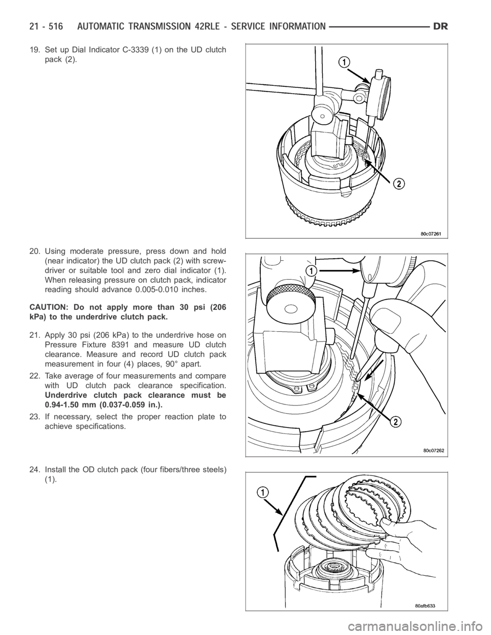
19. Set up Dial Indicator C-3339 (1) on the UD clutch
pack (2).
20. Using moderate pressure, press down and hold
(near indicator) the UD clutch pack (2) with screw-
driver or suitable tool and zero dial indicator (1).
When releasing pressure on clutch pack, indicator
reading should advance 0.005-0.010 inches.
CAUTION: Do not apply more than 30 psi (206
kPa) to the underdrive clutch pack.
21. Apply 30 psi (206 kPa) to the underdrive hose on
Pressure Fixture 8391 and measure UD clutch
clearance. Measure and record UD clutch pack
measurement in four (4) places, 90° apart.
22. Take average of four measurements and compare
with UD clutch pack clearance specification.
Underdrive clutch pack clearance must be
0.94-1.50 mm (0.037-0.059 in.).
23. If necessary, select the proper reaction plate to
achieve specifications.
24. Install the OD clutch pack(four fibers/three steels)
(1).
Page 3041 of 5267
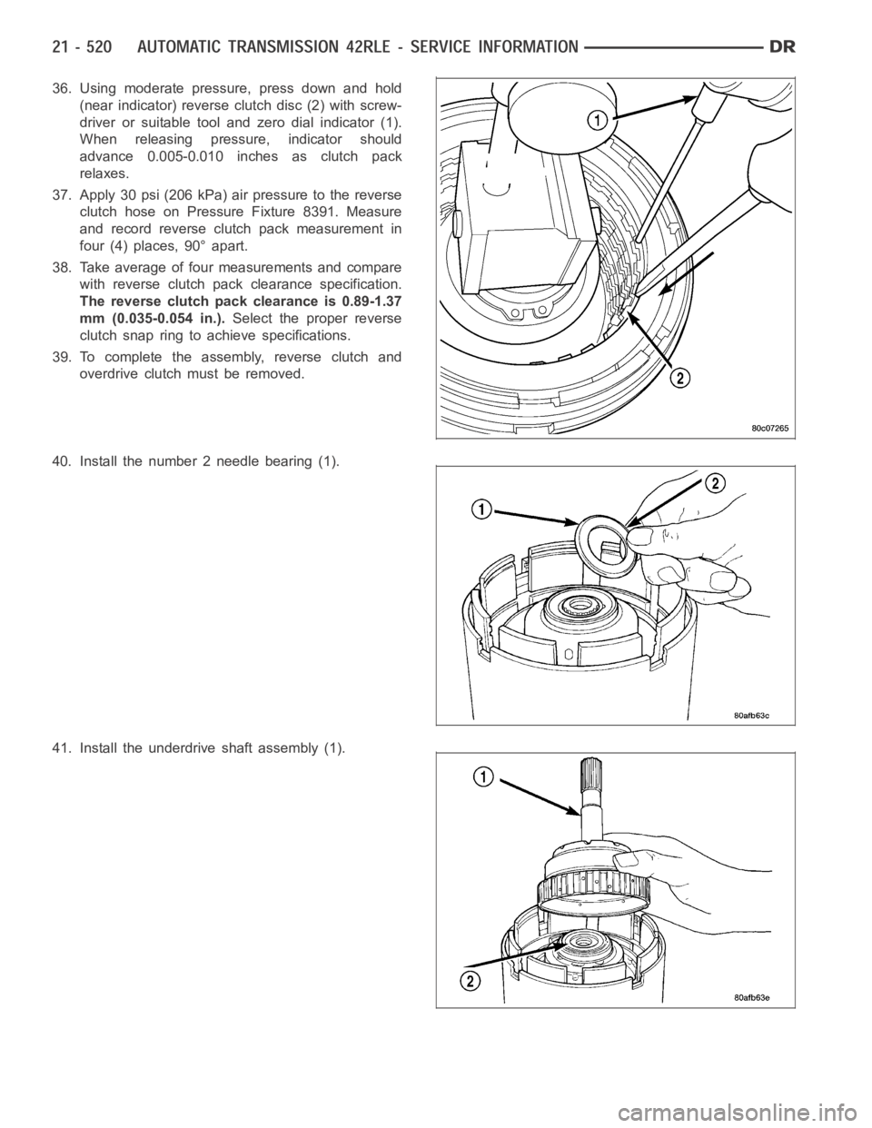
36. Using moderate pressure, press down and hold
(near indicator) reverse clutch disc (2) with screw-
driver or suitable tool and zero dial indicator (1).
When releasing pressure, indicator should
advance 0.005-0.010 inches as clutch pack
relaxes.
37. Apply 30 psi (206 kPa) air pressure to the reverse
clutch hose on Pressure Fixture 8391. Measure
and record reverse clutch pack measurement in
four (4) places, 90° apart.
38. Take average of four measurements and compare
with reverse clutch pack clearance specification.
The reverse clutch pack clearance is 0.89-1.37
mm (0.035-0.054 in.).Select the proper reverse
clutch snap ring to achieve specifications.
39. To complete the assembly, reverse clutch and
overdrive clutch must be removed.
40. Install the number 2 needle bearing (1).
41. Install the underdrive shaft assembly (1).