2006 DODGE RAM SRT-10 ECO mode
[x] Cancel search: ECO modePage 1868 of 5267
SOLENOID-MDS
DESCRIPTION
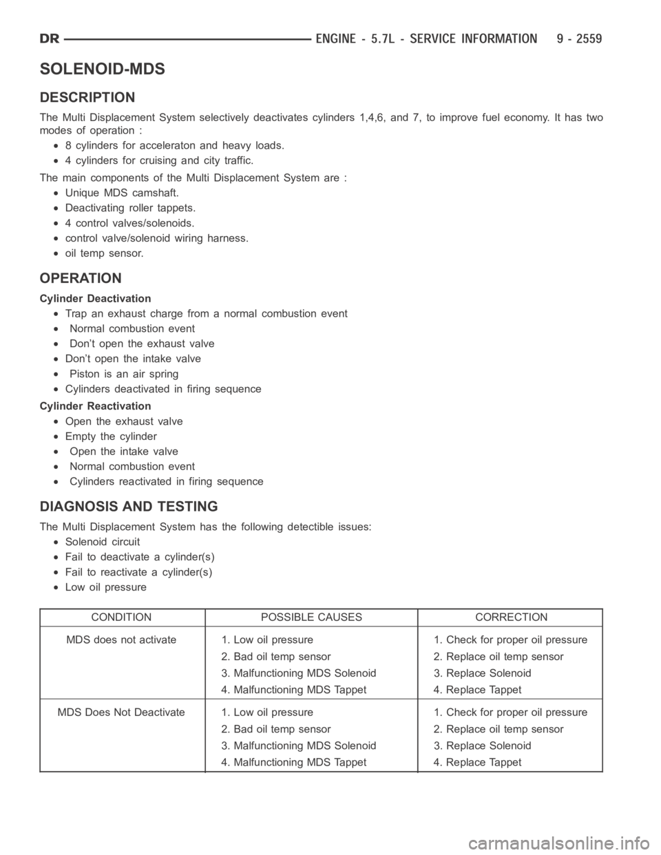
The Multi Displacement System selectively deactivates cylinders 1,4,6,and 7, to improve fuel economy. It has two
modes of operation :
8 cylinders for acceleraton and heavy loads.
4 cylinders for cruising and city traffic.
The main components of the Multi Displacement System are :
Unique MDS camshaft.
Deactivating roller tappets.
4 control valves/solenoids.
control valve/solenoid wiring harness.
oil temp sensor.
OPERATION
Cylinder Deactivation
Trap an exhaust charge from a normal combustion event
Normal combustion event
Don’t open the exhaust valve
Don’t open the intake valve
Piston is an air spring
Cylinders deactivated in firing sequence
Cylinder Reactivation
Open the exhaust valve
Empty the cylinder
Open the intake valve
Normal combustion event
Cylinders reactivated in firing sequence
DIAGNOSIS AND TESTING
The Multi Displacement System has the following detectible issues:
Solenoid circuit
Fail to deactivate a cylinder(s)
Fail to reactivate a cylinder(s)
Low oil pressure
CONDITION POSSIBLE CAUSES CORRECTION
MDS does not activate 1. Low oil pressure 1. Check for proper oil pressure
2. Bad oil temp sensor 2. Replace oil temp sensor
3. Malfunctioning MDS Solenoid 3. Replace Solenoid
4. Malfunctioning MDS Tappet 4. Replace Tappet
MDS Does Not Deactivate 1. Low oil pressure 1. Check for proper oil pressure
2. Bad oil temp sensor 2. Replace oil temp sensor
3. Malfunctioning MDS Solenoid 3. Replace Solenoid
4. Malfunctioning MDS Tappet 4. Replace Tappet
Page 1915 of 5267
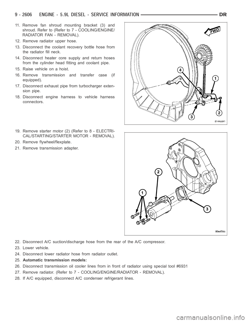
11. Remove fan shroud mounting bracket (3) and
shroud. Refer to (Refer to 7 - COOLING/ENGINE/
RADIATOR FAN - REMOVAL).
12. Remove radiator upper hose.
13. Disconnect the coolant recovery bottle hose from
the radiator fill neck.
14. Disconnect heater core supply and return hoses
from the cylinder head fitting and coolant pipe.
15. Raise vehicle on a hoist.
16. Remove transmission and transfer case (if
equipped).
17. Disconnect exhaust pipe from turbocharger exten-
sion pipe.
18. Disconnect engine harness to vehicle harness
connectors.
19. Remove starter motor (2) (Refer to 8 - ELECTRI-
CAL/STARTING/STARTER MOTOR - REMOVAL).
20. Remove flywheel/flexplate.
21. Remove transmission adapter.
22. Disconnect A/C suction/discharge hose from the rear of the A/C compressor.
23. Lower vehicle.
24. Disconnect lower radiator hose from radiator outlet.
25.Automatic transmission models:
26. Disconnect transmission oil cooler lines from in front of radiator using special tool #6931
27. Remove radiator. (Refer to 7 - COOLING/ENGINE/RADIATOR - REMOVAL).
28. If A/C equipped, disconnect A/C condenser refrigerant lines.
Page 1966 of 5267
CAMSHAFT & BEARINGS (IN BLOCK)
REMOVAL
CAMSHAFT BEARINGS
NOTE: Measure the diameter of each bore. If the camshaft bore for the cam bushing is worn beyond the
limit, install a new service bushing. Inspect the rest of the camshaft bores for damage or excessive wear.If
the bores without a bushing are worn beyond the limit, the engine must be removed for machining and
installation of service bushings. If badly worn, replace the cylinder block.
1. Remove the camshaft (Refer to 9 - ENGINE/ENGINE BLOCK/CAMSHAFT & BEARINGS (IN BLOCK) -
REMOVAL).
2. Remove the bushing from the No.1 bore.
3. Mark the cylinder block so you can align the oil hole in the cylinder blockwith the oil hole in the bushing.
CAMSHAFT
1. Disconnect both battery negative cables.
2. Recover A/C refrigerant (if A/C equipped) (Refer to 24 - HEATING & AIR CONDITIONING/PLUMBING - STAN-
DARD PROCEDURE).
3. Raise vehicle on hoist.
4. Drain engine coolant into container suitable for re-use (Refer to 7 - COOLING - STANDARD PROCEDURE).
5. Lower vehicle.
6. Remove radiator upper hose.
7. Remove viscous fan/drive/shroud assembly (Refer to 7 - COOLING/ENGINE/RADIATOR FAN - REMOVAL).
8. Disconnect the coolant recovery bottle hose from the radiator filler neck.
9. Disconnect lower radiator hose from radiator outlet.
10.Automatic Transmission models:Disconnect transmission oil cooler lines from front of radiator using Special
Tool 6931 (unless equipped with finger-release disconnect).
11. Remove radiator mounting screws and lift radiator out of engine compartment.
12. Remove upper radiator support panel.
13. If A/C equipped, disconnect A/C condenser refrigerant lines.
14. Disconnect charge air cooler piping from the cooler inlet and outlet.
15. Remove the two charge air cooler mounting bolts.
16. Remove charge air cooler (and A/C condenser if equipped) from vehicle.
17. Remove accessory drive belt (Refer to 7 - COOLING/ACCESSORY DRIVE/DRIVE BELTS - REMOVAL).
18. Remove accessory drive belt tensioner.
19. Remove the fan support/hub assembly.
20. Remove crankshaft damper and speed indicator ring (Refer to 9 - ENGINE/ENGINE BLOCK/VIBRATION
DAMPER - REMOVAL).
21. Remove the gear cover-to-housing bolts and gently pry the cover away from the housing, taking care not to mar
the sealing surfaces. Remove dust seal with cover.
22. Using Special Tool 7471–B Crankshaft Barring Tool, rotate the crankshaft to align the timing marks on the
crankshaft and the camshaft gears.
23. Remove the cylinder head cover (Refer to 9 - ENGINE/CYLINDER HEAD/CYLINDER HEAD COVER(S) -
REMOVAL).
Page 2247 of 5267
SENSOR - FUEL LEVEL SENDING UNIT
DESCRIPTION
The fuel gauge sending unit (fuel level sensor) is attached to the side of the fuel pump module. The sending unit
consists of a float, an arm, and a variable resistor track (card).
OPERATION
The fuel pump module has 4 different circuits (wires). Two of these circuits are used for the fuel gauge sending unit
for fuel gauge operation, and for certain OBD II emission requirements. The other 2 wires are used for electric fuel
pump operation.
For Fuel Gauge Operation:A constant current source is supplied to the resistor track on the fuel gauge sending
unit. This is fed directly from the Powertrain Control Module (PCM).NOTE: For diagnostic purposes, this 12V
power source can only be verified with the circuit opened (fuel pump moduleelectrical connector
unplugged). With the connectors plugged, output voltages will vary from about 0.6 volts at FULL, to about
8.6 volts at EMPTY (about 8.6 volts at EMPTY for Jeep models, and about 7.0 volts at EMPTY for Dodge
Truck models).The resistor track is used to vary the voltage (resistance) depending on fuel tank float level. As fuel
level increases, the float and arm move up, which decreases voltage. As fuel level decreases, the float and arm
move down, which increases voltage. The varied voltage signal is returnedback to the PCM through the sensor
return circuit.
Both of the electrical circuits between the fuel gauge sending unit and thePCM are hard-wired (not multi-plexed).
After the voltage signal is sent from the resistor track, and back to the PCM, the PCM will interpret the resistance
(voltage) data and send a message across the multi-plex bus circuits to theinstrument panel cluster. Here it is
translated into the appropriate fuel gauge level reading. Refer to Instrument Panel for additional information.
For OBD II Emission Monitor Requirements:The PCM will monitor the voltage output sent from the resistor track
on the sending unit to indicate fuel level. The purpose of this feature is toprevent the OBD II system from recording/
setting false misfire and fuel systemmonitor diagnostic trouble codes. The feature is activated if the fuel level in the
tank is less than approximately 15 percent of its rated capacity. If equipped with a Leak Detection Pump (EVAP
system monitor), this feature will also be activated if the fuel level in the tank is more than approximately 85 percent
of its rated capacity.
REMOVAL
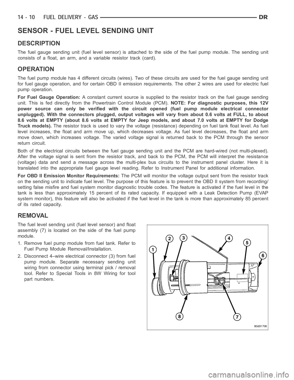
The fuel level sending unit (fuel level sensor) and float
assembly (7) is located on the side of the fuel pump
module.
1. Remove fuel pump module from fuel tank. Refer to
Fuel Pump Module Removal/Installation.
2. Disconnect 4–wire electrical connector (3) from fuel
pump module. Separate necessary sending unit
wiring from connector using terminal pick / removal
tool. Refer to Special Tools in 8W Wiring for tool
part numbers.
Page 2255 of 5267
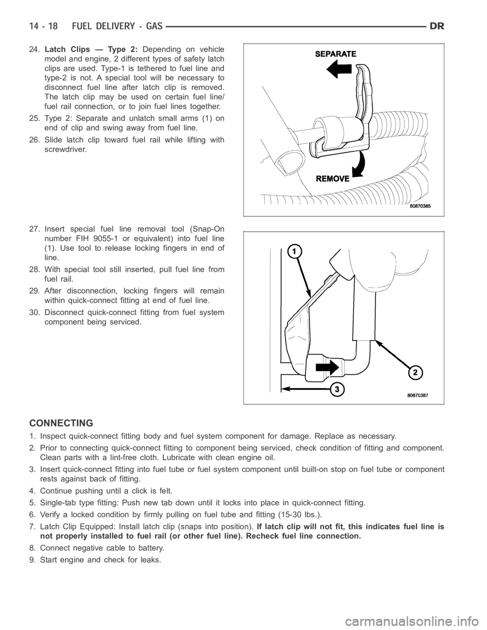
24.Latch Clips — Type 2:Depending on vehicle
model and engine, 2 different types of safety latch
clips are used. Type-1 is tethered to fuel line and
type-2 is not. A special tool will be necessary to
disconnect fuel line after latch clip is removed.
The latch clip may be used on certain fuel line/
fuel rail connection, or to join fuel lines together.
25. Type 2: Separate and unlatch small arms (1) on
end of clip and swing away from fuel line.
26. Slide latch clip toward fuel rail while lifting with
screwdriver.
27. Insert special fuel line removal tool (Snap-On
number FIH 9055-1 or equivalent) into fuel line
(1). Use tool to release locking fingers in end of
line.
28. With special tool still inserted, pull fuel line from
fuel rail.
29. After disconnection, locking fingers will remain
within quick-connect fitting at end of fuel line.
30. Disconnect quick-connect fitting from fuel system
component being serviced.
CONNECTING
1. Inspect quick-connect fitting body and fuel system component for damage. Replace as necessary.
2. Prior to connecting quick-connect fitting to component being serviced, check condition of fitting and component.
Clean parts with a lint-free cloth. Lubricate with clean engine oil.
3. Insert quick-connect fitting intofuel tube or fuel system component until built-on stop on fuel tube or component
rests against back of fitting.
4. Continue pushing until a click is felt.
5. Single-tab type fitting: Push new tab down until it locks into place in quick-connect fitting.
6. Verify a locked condition by firmly pulling on fuel tube and fitting (15-30 lbs.).
7. Latch Clip Equipped: Install latch clip (snaps into position).If latch clip will not fit, this indicates fuel line is
not properly installed to fuel rail (or other fuel line). Recheck fuel lineconnection.
8. Connect negative cable to battery.
9. Start engine and check for leaks.
Page 2271 of 5267
TA N K - F U E L
DESCRIPTION
The fuel tank is constructed of a plastic material. Its main functions are for fuel storage and for placement of the fuel
pump module, and (if equipped) certain ORVR components.
OPERATION
All models pass a full 360 degree rollover test without fuel leakage. To accomplish this, fuel and vapor flow controls
are required for all fuel tank connections.
Two check (control) valves are mounted into the top of the fuel tank. Refer to Fuel Tank Check Valve for additional
information.
An evaporation control system is connected to the fuel tank to reduce emissions of fuel vapors into the atmosphere.
When fuel evaporates from the fuel tank, vapors pass through vent hoses or tubes to a charcoal canister where
they are temporarily held. When the engine is running, the vapors are drawninto the intake manifold. Certain mod-
els are also equipped with a self-diagnosing system using a Leak DetectionPump (LDP) or NVLD Pump, and/or an
On-Board Refueling Vapor Recovery (ORVR) system. Refer to Emission Control System for additional information.
REMOVAL- EXCEPT DIESEL
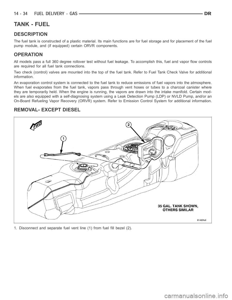
1. Disconnect and separate fuel vent line (1) from fuel fill bezel (2).
Page 2738 of 5267
P0602-CONTROL MODULE PROGRAMMING ERROR/NOT PROGRAMMED
For a complete wiring diagramRefer to Section 8W.
When Monitored:
Check for generic software is made at power-up.
Set Condition:
If generic software is found, the MIL will light immediately. This DTC is designed to signal the technician that
the controller still has generic software installed.
Possible Causes
PCM - PROGRAMMING ERROR
Always perform the Pre-Diagnostic Troubleshooting procedure before proceeding. (Refer to 21 - TRANSMIS-
SION/TRANSAXLE/AUTOMATIC - 42RLE - STANDARD PROCEDURE)
Theory of Operation
The controller is programmed during manufacturing with generic softwareto facilitate testing. This software does not
have the proper calibrations to control a transmission in a vehicle. The check for generic software is made at power-
up. If generic software is found, the MIL will light immediately and the MILwill stay on even if the fault is cleared,
until the proper software is installed.Note:Transmissionwillbeplacedin limp-in mode.
Diagnostic Test
1.CONTROL MODULE PROGRAMMING ERROR
NOTE: Controller is programmed with generic software and will not allow the correct vehicle Powertrain
management.
Record the controller part number.
UpdatethecontrollerwiththecorrectsoftwareinaccordancewiththeService Information.
Verify that the controller updated successfully.
Te s t C o m p l e t e
Perform 42RLE TRANSMISSION VERIFICATION TEST - VER 1. (Refer to 21 - TRANSMISSION/
TRANSAXLE/AUTOMATIC - 42RLE - STANDARD PROCEDURE)
Page 2769 of 5267

P0725-ENGINE SPEED SENSOR CIRCUIT
For a complete wiring diagramRefer to Section 8W.
When Monitored:
Whenever the engine is running.
Set Condition:
The Engine RPM is less than 390 or greater than 8000 for more than 2 seconds while the engine is running.
Possible Causes
ENGINE DTCS PRESENT
POWERTRAIN CONTROL MODULE
Always perform the Pre-Diagnostic Troubleshooting procedure before proceeding. (Refer to 21 - TRANSMIS-
SION/TRANSAXLE/AUTOMATIC - 42RLE - STANDARD PROCEDURE)
Theory of Operation
The PCM uses a dual port RAM internal to the controller to send the engine speed signal to the Transmission
Control System. The calculated engine RPM is compared to a minimum and maximum value. If the PCM interprets
this signal to be out of range when the engine is running the code is set. The MIL illuminates after 10 seconds of
vehicle operation and the transmission system defaults to Limp-in mode.
Diagnostic Test
1.CHECK IF THE DTC IS CURRENT
Start the engine.
NOTE: This DTC is not a Transmission Input Speed Sensor DTC.
With the scan tool, read transmission DTCs.
Is the status Active for this DTC or is the STARTS SINCE SET counter set at 0?
Ye s>>
Go To 2
No>>
Go To 3
2.CHECK IF ENGINE DTCS ARE PRESENT
With the scan tool, read engine DTCs.
Are there any engine DTC’s present?
Ye s>>
Refer to Section 9 – Engine Electrical Diagnostics and perform the appropriate diagnostic procedure.
Perform 42RLE TRANSMISSION VERIFICATION TEST - VER 1. (Refer to 21 - TRANSMISSION/
TRANSAXLE/AUTOMATIC - 42RLE - STANDARD PROCEDURE)
No>>
Using the schematics as a guide, check the Powertrain Control Module (PCM)terminals for corrosion,
damage, or terminal push out. Pay particular attention to all power and ground circuits. Check for Ser-
vice Information Tune-ups or Service Bulletins for any possible causes that may apply. If no problems
are found, replace the PCM per the Service Information. With the scan tool,perform QUICK LEARN.
Perform 42RLE TRANSMISSION VERIFICATION TEST - VER 1. (Refer to 21 - TRANSMISSION/
TRANSAXLE/AUTOMATIC - 42RLE - STANDARD PROCEDURE)