2006 DODGE RAM SRT-10 ECO mode
[x] Cancel search: ECO modePage 463 of 5267

POWERTRAIN VERIFICATION TEST VER - 4 (DIESEL)
1.POWERTRAIN VERIFICATION TEST VER - 4 (DIESEL)
1. Check if any of the following conditions exist.
2. The ECM has been disconnected or replace.
3. The Battery power has been disconnected.
4. Inspect the vehicle to ensure that all engine components are properly installed and connected. Reassemble and
reconnect components as necessary.
5. With the DRBIII
,eraseDTCs.
6. If the ECM has been replaced, perform steps 11 through 13, then continue with the verification.
7. If ECM has been changed and correct VIN and mileage have not been programmed, a DTC will be set in ABS
and Air bag modules. In addition, if vehicle is equipped with a Sentry Key Immobilizer Module (SKIM), Secret Key
data must be updated to enable start.
8. For ABS and Air Bag systems: Enter correct VIN and Mileage in ECM. Erase codes in ABS and Air Bag modules.
9. For SKIM theft alarm: Connect DRBIII
to data link conn. Go to Theft Alarm, SKIM, Misc. and place SKIM in
secured access mode, by using the appropriate PIN code for this vehicle. Select Update the Secret Key data. Data
will be transferred from SKIM to PCM
10. Turn the speed control ON (if equipped, cruise light will be on).
11. Depress and release the SET Switch. If the speed control did not engage,the repair is not complete. Check for
TSBs that pertain to speed control problem and then, if necessary, return to Symptom List.
12. Depress and hold the RESUME/ACCEL Switch. If the vehicle speed did not increase by at least 2 mph, the
repair is not complete. Check for TSBs that pertain to speed control problem and then, if necessary, return to Symp-
tom List.
13. Press and hold the COAST switch. The vehicle speed should decrease. If it did not decrease, the repair is not
complete. Check for TSBs that pertain to speed control problem and then, ifnecessary, return to Symptom List.
14. Using caution, depress and release the brake pedal. If the speed control did not disengage, the repair is not
complete. Check for TSBs that pertain to speed control problem and then, ifnecessary, return to Symptom List.
15. Bring the vehicle speed back up to 35 MPH.
16. Depress the RESUME/ACCEL switch. If the speed control did not resume the previously set speed, the repair
is not complete. Check for TSBs that pertain to speed control problem and then, if necessary, return to Symptom
List.
17. Hold down the SET switch. If the vehicle did not decelerate, the repair is not complete. Check for TSBs that
pertain to speed control problem and then, if necessary, return to SymptomList.
18. Ensure vehicle speed is greater than 35 mph and release the SET Switch. If vehicle did not adjust and set a
new vehicle speed, the repair is not complete. Check for TSBs that pertain to speed control problem and then, if
necessary, return to Symptom List.
19. Depress and release the CANCEL switch. If the speed control did not disengage, the repair is not complete.
Check for TSBs that pertain to speed control problem and then, if necessary, return to Symptom List.
20. Bring the vehicle speed back up above 35 mph and engage speed control.
21. Depress the OFF switch to turn OFF, (Cruise light will be off). If the speed control did not disengage, the repair
is not complete. Check for TSBs that pertain to speed control problem and then, if necessary, return to Symptom
List.
22. If the vehicle successfully passed all of the previous tests, the speedcontrol system is now functioning as
designed. The repair is now complete.
23. NOTE: OVERSHOOT/UNDERSHOOT FOLLOWING SPEED CONTROL SET.
24. If the vehicle operator repeatedly presses and releases the SET buttonwith their foot off of the accelerator
(referred to as
lift foot set), the vehicle may accelerate and exceed the desired set speed by up to 5 mph (8km/h).
25. It may also decelerate to less than the desired set speed, before finally achieving the desired set speed.
26. The Speed Control System has an adaptive strategy that compensates forvehicle-to-vehicle variations in speed
control cable lengths.
27. When the speed control is set with the vehicles operators foot off of theaccelerator pedal, the speed control
thinks there is excessive speed control cable slack and adapts accordingly.
28. If the
lift foot setsare continually used, a speed control overshoot/undershoot condition will develop.
29. To
unlearnthe overshoot/undershoot condition, the vehicle operator has to press and release the set button
Page 465 of 5267

POWERTRAIN VERIFICATION TEST VER - 5 (DIESEL)
Diagnostic Test
1.POWERTRAIN VERIFICATION TEST VER - 5 (DIESEL)
1. Check if any of the following conditions exist.
2. The ECM has been disconnected or replace.
3. The Battery power has been disconnected.
4. Inspect the vehicle to ensure that all engine components are properly installed and connected. Reassemble and
reconnect components as necessary.
5. If any existing diagnostic trouble codes have not been repaired, go to Symptom List and follow path specified.
6. Connect the scan tool to the data link connector.
7. Ensure the fuel tank has at least a quarter tank of fuel. Turn off all accessories.
8. Perform steps 15 through 17 if the PCM has been replaced. Then proceed with the verification. If the ECM has
not been replaced skip those steps and continue verification.
9. If ECM has been changed and correct VIN and mileage have not been programmed, a DTC will be set in ABS
and Air bag modules. In addition, if vehicle is equipped with a Sentry Key Immobilizer Module (SKIM), Secret Key
data must be updated to enable start.
10. For ABS and Air Bag systems: Enter correct VIN and Mileage in ECM. Erase codes in ABS and Air Bag mod-
ules.
11. For SKIM theft alarm: Connect scan tool to data link connector to Theft Alarm, SKIM, Misc. and place SKIM in
secured access mode by using appropriate PIN code for this vehicle. SelectUpdate the Secret Key data. Data will
be transferred from SKIM to PCM.
12. If a Comprehensive Component DTC was repaired, perform steps 10-13. Ifa Major OBDII Monitor DTC was
repaired skip those steps and continue verification.
13. After the ignition has been off for at least 10 seconds, restart the vehicle and run 2 minutes.
14. If there are no new DTC’s, the repair was successful and is now complete.Erase DTC’s and disconnect the
scan tool.
15. If the repaired DTC has reset, the repair is not complete. Check for any related TSB’s or flash updates and
return to the Symptom list.
16. If another DTC has set, return to the Symptom List and follow the path specified for that DTC.
17. With the scan tool, monitor the appropriate pre-test enabling conditions until all conditions have been met. Once
the conditions have been met, switch screen to the appropriate OBDII monitor, (Audible beeps when the monitor is
running).
18. If the monitor ran, the repair was successful and is now complete. EraseDTC’s and disconnect the scan tool.
19. If the repaired OBDII trouble code has reset or was seen in the monitor while on the road test, the repair is not
complete. Check for any related technical service bulletins or flash updates and return to Symptom List.
20. If another DTC has set, return to the Symptom List and follow the path specified for that DTC.
Is any DTC(s) present?
Ye s>>
Repair is not complete, refer to appropriate symptom.
No>>
Repair is complete.
Page 1054 of 5267
Theory of Operation
The fuel feedback system will maintain a stoiciometric fuel/air mixture,14.7:1, by modifying the injector pulsewidth
according to the oxygen content of the exhaust gas. The PCM makes short termand long term fuel corrections to
maintain stoiciometric fuel/air ratio for best catalytic converter efficiency. Short term fuel correction is based on
upstream O2 sensor output and is designed for quick engine response. The long term fuel correction compensated
for variations in the engine specifications, sensor tolerances and component aging and is designed to correct rich
and lean conditions over a longer period of time.
When Monitored:
With the engine running in closed loop mode, the ambient/battery temperature above 20 deg. F and altitude
below 8500 ft.
Set Condition:
If the PCM multiplies short term compensation by long term adaptive and a certain percentage is exceeded for
two trips, a freeze frame is stored, the MIL illuminates and a trouble code is stored. Two Trip Fault. Three good
trips to turn off the MIL
Possible Causes
FUEL PRESSURE OUT OF SPECS
RESTRICTED FUEL SUPPLY LINE
FUEL PUMP INLET STRAINER PLUGGED
FUEL PUMP MODULE
O2 SENSOR
(K41) O2 SENSOR 1/1 SIGNAL CIRCUIT SHORTED TO GROUND
O2 SENSOR 1/1 HEATER OPERATION
TP SENSOR
MAP SENSOR
ECT SENSOR
ENGINE MECHANICAL CONDITION
FUEL FILTER/PRESSURE REGULATOR
PCM
Always perform the Pre-Diagnostic Troubleshooting procedure before proceeding. (Refer to 9 - ENGINE -
DIAGNOSIS AND TESTING).
Diagnostic Test
1.GOOD TRIP EQUAL TO ZERO
NOTE: Check for contaminates that may have damaged the O2 Sensor: contaminated fuel, unapproved sil-
icone, oil and coolant.
Ignition on, engine not running.
With the scan tool, read DTCs and record the related Freeze Frame data.
Is the Good Trip Counter displayed and equal to zero?
Ye s>>
Go To 2
No>>
Refer to the INTERMITTENT CONDITION Diagnostic Procedure.
Perform the POWERTRAIN VERIFICATION TEST. (Refer to 9 - ENGINE - STANDARD PROCEDURE)
Page 1061 of 5267
Theory of Operation
The fuel feedback system will maintain a stoiciometric fuel/air mixture,14.7:1, by modifying the injector pulsewidth
according to the oxygen content of the exhaust gas. The PCM makes short termand long term fuel corrections to
maintain stoiciometric fuel/air ratio for best catalytic converter efficiency. Short term fuel correction is based on
upstream O2 sensor output and is designed for quick engine response. The long term fuel correction compensated
for variations in the engine specifications, sensor tolerances and component aging and is designed to correct rich
and lean conditions over a longer period of time.
When Monitored:
With the engine running in closed loop mode, the ambient/battery temperature above 20 deg. F and altitude
below 8500 ft.
Set Condition:
If the PCM multiplies short term compensation by long term adaptive and a purge fuel multiplier and the result
is below a certain value for 30 seconds over two trips, a freeze frame is stored, the MIL illuminates and a
trouble code is stored. Two Trip Fault. Three good trips to turn off the MIL.
Possible Causes
O2 SENSOR
(K41) O2 SENSOR 1/1 SIGNAL CIRCUIT OPEN
(K41) O2 SENSOR 1/1 SIGNAL CIRCUIT SHORTED TO VOLTAGE
1/1 O2 SENSOR HEATER OPERATION
EVAP SYSTEM OPERATION
TP SENSOR VOLTAGE GREATER THAN 0.92 OF A VOLT WITH THROTTLE CLOSED
TP SENSOR
FUEL FILTER/PRESSURE REGULATOR
MAP SENSOR
ECT SENSOR
ENGINE MECHANICAL CONDITION
PCM
Always perform the Pre-Diagnostic Troubleshooting procedure before proceeding. (Refer to 9 - ENGINE -
DIAGNOSIS AND TESTING).
Diagnostic Test
1.GOOD TRIP EQUAL TO ZERO
NOTE: Check for contaminates that may have damaged the O2 Sensor: contaminated fuel, unapproved sil-
icone, oil and coolant.
Ignition on, engine not running.
With the scan tool, read DTCs and record the related Freeze Frame data.
NOTE: Any O2 Sensor, TPS, ECT, MAP, or EVAP DTCs must be repaired before continuing.
Is the Good Trip Counter displayed and equal to zero?
Ye s>>
Go To 2
No>>
Refer to the INTERMITTENT CONDITIONSymptom (Diagnostic Procedure).
Perform the POWERTRAIN VERIFICATION TEST. (Refer to 9 - ENGINE - STANDARD PROCEDURE)
Page 1067 of 5267
Theory of Operation
The fuel feedback system will maintain a stoiciometric fuel/air mixture,14.7:1, by modifying the injector pulsewidth
according to the oxygen content of the exhaust gas. The PCM makes short termand long term fuel corrections to
maintain stoiciometric fuel/air ratio for best catalytic converter efficiency. Short term fuel correction is based on
upstream O2 sensor output and is designed for quick engine response. The long term fuel correction compensated
for variations in the engine specifications, sensor tolerances and component aging and is designed to correct rich
and lean conditions over a longer period of time.
When Monitored:
With the engine running in closed loop mode, the ambient/battery temperature above 20 deg. F and altitude
below 8500 ft.
Set Condition:
If the PCM multiplies short term compensation by long term adaptive and a certain percentage is exceeded for
two trips, a freeze frame is stored, the MIL illuminates and a trouble code is stored. Two Trip Fault. Three good
trips to turn off the MIL.
Possible Causes
FUEL PRESSURE OUT OF SPECS
RESTRICTED FUEL SUPPLY LINE
FUEL PUMP INLET STRAINER PLUGGED
FUEL PUMP MODULE
O2 SENSOR
(K43) O2 SENSOR 2/1 SIGNAL CIRCUIT SHORTED TO GROUND
O2 SENSOR 2/1 HEATER OPERATION
TP SENSOR
MAP SENSOR
ECT SENSOR
ENGINE MECHANICAL CONDITION
FUEL FILTER/PRESSURE REGULATOR
PCM
Always perform the Pre-Diagnostic Troubleshooting procedure before proceeding. (Refer to 9 - ENGINE -
DIAGNOSIS AND TESTING).
Diagnostic Test
1.GOOD TRIP EQUAL TO ZERO
NOTE: Check for contaminates that may have damaged the O2 Sensor: contaminated fuel, unapproved sil-
icone, oil and coolant.
Ignition on, engine not running.
With the scan tool, read DTCs and record the related Freeze Frame data.
Is the Good Trip Counter displayed and equal to zero?
Ye s>>
Go To 2
No>>
Refer to the INTERMITTENT CONDITION Diagnostic Procedure.
Perform the POWERTRAIN VERIFICATION TEST. (Refer to 9 - ENGINE - STANDARD PROCEDURE)
Page 1074 of 5267

Theory of Operation
The fuel feedback system will maintain a stoiciometric fuel/air mixture,14.7:1, by modifying the injector pulsewidth
according to the oxygen content of the exhaust gas. The PCM makes short termand long term fuel corrections to
maintain stoiciometric fuel/air ratio for best catalytic converter efficiency. Short term fuel correction is based on
upstream O2 sensor output and is designed for quick engine response. The long term fuel correction compensated
for variations in the engine specifications, sensor tolerances and component aging and is designed to correct rich
and lean conditions over a longer period of time.
When Monitored:
With the engine running in closed loop mode, the ambient/battery temperature above 20 deg. F and altitude
below 8500 ft.
Set Condition:
If the PCM multiplies short term compensation by long term adaptive and a purge fuel multiplier and the result
is below a certain value for 30 seconds over two trips, a freeze frame is stored, the MIL illuminates and a
trouble code is stored. Two Trip Fault. Three good trips to turn off the MIL.
Possible Causes
O2 SENSOR
(K43) O2 SENSOR 2/1 SIGNAL CIRCUIT OPEN
(K43) O2 SENSOR 2/1 SIGNAL CIRCUIT SHORTED TO VOLTAGE
2/1 O2 SENSOR HEATER OPERATION
EVAP SYSTEM OPERATION
TP SENSOR VOLTAGE GREATER THAN 0.92 OF A VOLT WITH THROTTLE CLOSED
TP SENSOR
FUEL FILTER/PRESSURE REGULATOR
MAP SENSOR
ECT SENSOR
ENGINE MECHANICAL CONDITION
PCM
Always perform the Pre-Diagnostic Troubleshooting procedure before proceeding. (Refer to 9 - ENGINE -
DIAGNOSIS AND TESTING).
Diagnostic Test
1.GOOD TRIP EQUAL TO ZERO
NOTE: Check for contaminates that may have damaged the O2 Sensor: contaminated fuel, unapproved sil-
icone, oil and coolant.
Ignition on, engine not running.
With the scan tool, read DTCs and record the related Freeze Frame data.
NOTE: Any O2 Sensor, TPS, ECT, MAP, or EVAP DTCs must be repaired before continuing.
Is the Good Trip Counter displayed and equal to zero?
Ye s>>
Go To 2
No>>
Refer to the INTERMITTENT CONDITIONSymptom (Diagnostic Procedure).
Perform the POWERTRAIN VERIFICATION TEST. (Refer to 9 - ENGINE - STANDARD PROCEDURE)
Page 1274 of 5267
5.EVAPORATIVE EMISSION LEAK DETECTION
NOTE: A thorough visual inspection of the Evap system hoses, tubes, and connections may save time in
your diagnosis. Look for any physical damage or signs of wetness at connections. The strong smell of fuel
vapors may also aid diagnosis.
To continue testing, you will need Miller Tool #8404A Evaporative Emissions Leak Detector (EELD).
Remove the Air supply hose from the service port (if equipped) or from the #8404-ADP adapter.
Connect the SMOKE supply tip (black hose) to the service port (if equipped)or to the #8404-ADP adapter.
Set the smoke/air control switch to SMOKE.
NOTE: The flow meter indicator ball will not move in the smoke mode.
Press the remote smoke/air start button.
NOTE: Make sure that smoke has filled the EVAP system by continuing to presstheremotesmoke/airstart
button, remove the vehicle fuel cap, and wait for the smoke to exit. Once smoke is indicated reinstall the
fuel cap.
NOTE: For optimal performance, introduce smoke into the system for an additional 60 seconds; continue
introducing smoke at 15 second intervals, as necessary.
While still holding the remote smoke/air start button, use the white light(#8404-CLL) to follow the EVAP system
path, and look for the source of the leak indicated by exiting smoke.
If a leak is concealed from view (i.e., top of fuel tank), release the remotesmoke/air start button, and use the ultra-
violet (UV) black light #8404-UVL and the yellow goggles 8404-20 to look for residual traces of dye that is left
behind by the smoke.
The exiting smoke deposits a residual fluid that is either bright green or bright yellow in color when viewed with a
UV light.
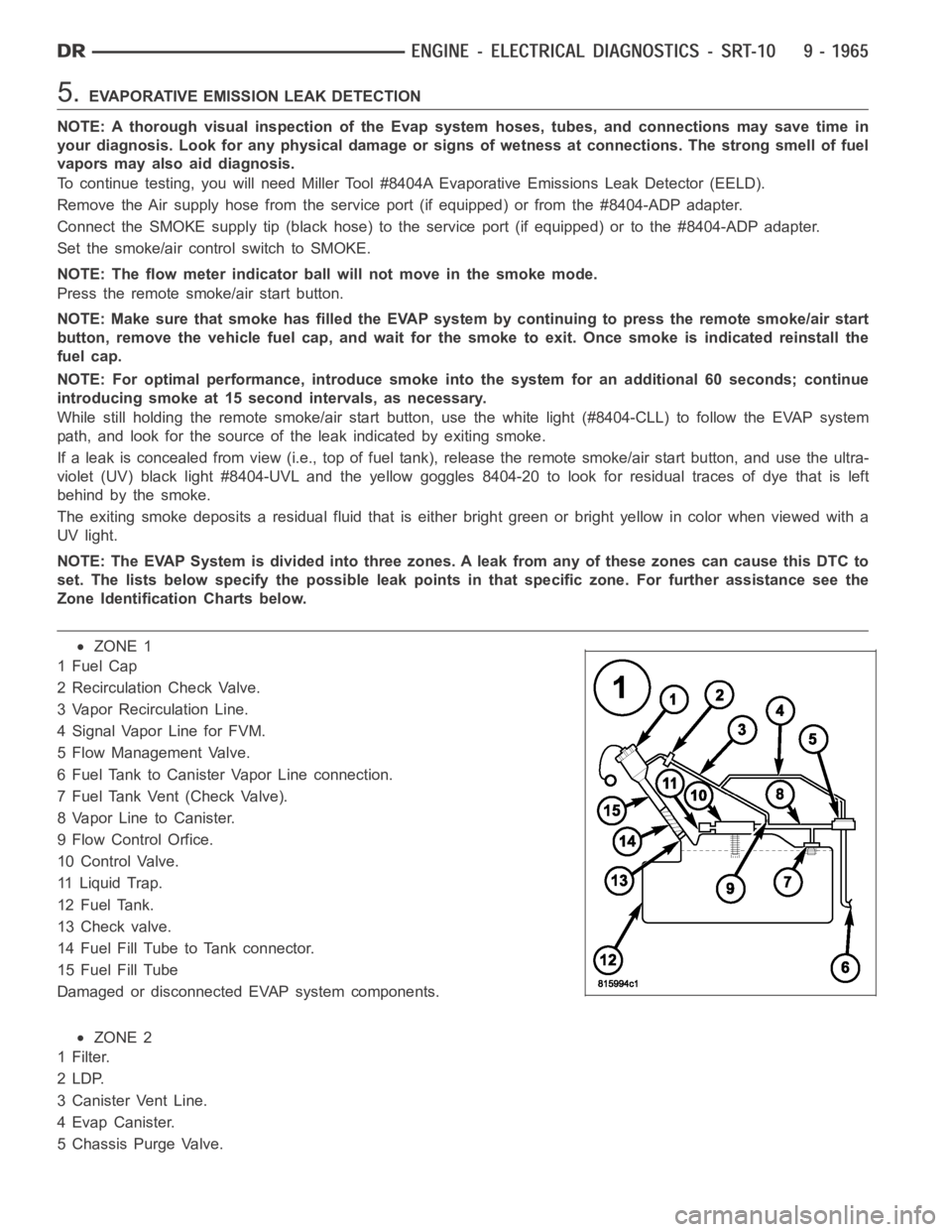
NOTE: The EVAP System is divided into three zones. A leak from any of these zonescancausethisDTCto
set. The lists below specify the possible leak points in that specific zone. For further assistance see the
Zone Identification Charts below.
ZONE 1
1FuelCap
2 Recirculation Check Valve.
3 Vapor Recirculation Line.
4 Signal Vapor Line for FVM.
5 Flow Management Valve.
6 Fuel Tank to Canister Vapor Line connection.
7 Fuel Tank Vent (Check Valve).
8 Vapor Line to Canister.
9 Flow Control Orfice.
10 Control Valve.
11 Liquid Trap.
12 Fuel Tank.
13 Check valve.
14 Fuel Fill Tube to Tank connector.
15 Fuel Fill Tube
Damaged or disconnected EVAP system components.
ZONE 2
1Filter.
2LDP.
3 Canister Vent Line.
4EvapCanister.
5 Chassis Purge Valve.
Page 1284 of 5267
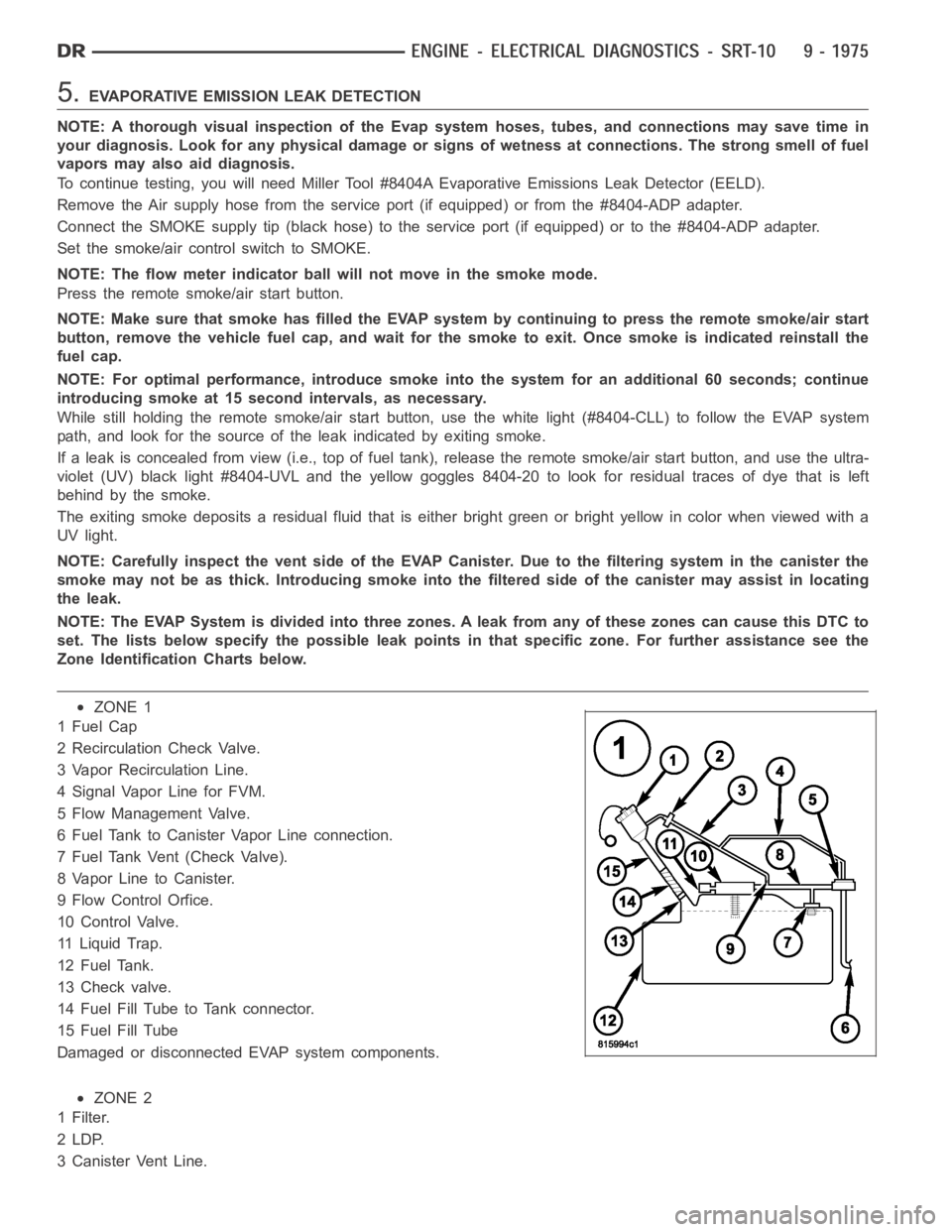
5.EVAPORATIVE EMISSION LEAK DETECTION
NOTE: A thorough visual inspection of the Evap system hoses, tubes, and connections may save time in
your diagnosis. Look for any physical damage or signs of wetness at connections. The strong smell of fuel
vapors may also aid diagnosis.
To continue testing, you will need Miller Tool #8404A Evaporative Emissions Leak Detector (EELD).
Remove the Air supply hose from the service port (if equipped) or from the #8404-ADP adapter.
Connect the SMOKE supply tip (black hose) to the service port (if equipped)or to the #8404-ADP adapter.
Set the smoke/air control switch to SMOKE.
NOTE: The flow meter indicator ball will not move in the smoke mode.
Press the remote smoke/air start button.
NOTE: Make sure that smoke has filled the EVAP system by continuing to presstheremotesmoke/airstart
button, remove the vehicle fuel cap, and wait for the smoke to exit. Once smoke is indicated reinstall the
fuel cap.
NOTE: For optimal performance, introduce smoke into the system for an additional 60 seconds; continue
introducing smoke at 15 second intervals, as necessary.
While still holding the remote smoke/air start button, use the white light(#8404-CLL) to follow the EVAP system
path, and look for the source of the leak indicated by exiting smoke.
If a leak is concealed from view (i.e., top of fuel tank), release the remotesmoke/air start button, and use the ultra-
violet (UV) black light #8404-UVL and the yellow goggles 8404-20 to look for residual traces of dye that is left
behind by the smoke.
The exiting smoke deposits a residual fluid that is either bright green or bright yellow in color when viewed with a
UV light.
NOTE: Carefully inspect the vent side of the EVAP Canister. Due to the filtering system in the canister the
smoke may not be as thick. Introducing smoke into the filtered side of the canister may assist in locating
the leak.
NOTE: The EVAP System is divided into three zones. A leak from any of these zonescancausethisDTCto
set. The lists below specify the possible leak points in that specific zone. For further assistance see the
Zone Identification Charts below.
ZONE 1
1FuelCap
2 Recirculation Check Valve.
3 Vapor Recirculation Line.
4 Signal Vapor Line for FVM.
5 Flow Management Valve.
6 Fuel Tank to Canister Vapor Line connection.
7 Fuel Tank Vent (Check Valve).
8 Vapor Line to Canister.
9 Flow Control Orfice.
10 Control Valve.
11 Liquid Trap.
12 Fuel Tank.
13 Check valve.
14 Fuel Fill Tube to Tank connector.
15 Fuel Fill Tube
Damaged or disconnected EVAP system components.
ZONE 2
1Filter.
2LDP.
3 Canister Vent Line.