2006 DODGE RAM SRT-10 ECO mode
[x] Cancel search: ECO modePage 4687 of 5267
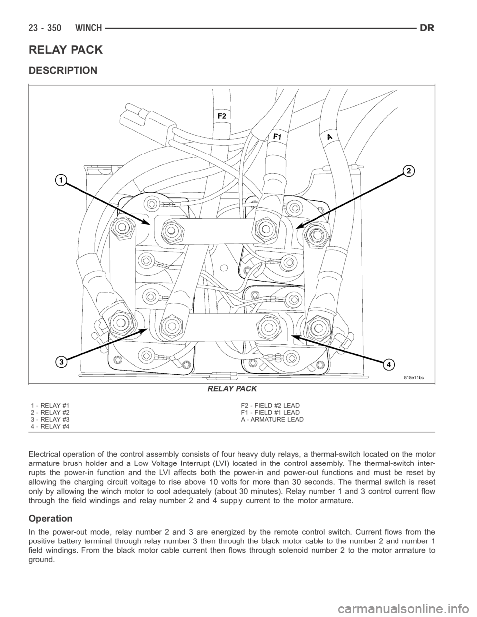
RELAY PACK
DESCRIPTION
Electrical operation of the control assembly consists of four heavy duty relays, a thermal-switch located on the motor
armature brush holder and a Low Voltage Interrupt (LVI) located in the control assembly. The thermal-switch inter-
rupts the power-in function and the LVI affects both the power-in and power-out functions and must be reset by
allowing the charging circuit voltage to rise above 10 volts for more than 30 seconds. The thermal switch is reset
only by allowing the winch motor to cool adequately (about 30 minutes). Relay number 1 and 3 control current flow
through the field windings and relay number 2 and 4 supply current to the motor armature.
Operation
In the power-out mode, relay number 2 and 3 are energized by the remote control switch. Current flows from the
positive battery terminal through relay number 3 then through the black motor cable to the number 2 and number 1
field windings. From the black motor cable current then flows through solenoid number 2 to the motor armature to
ground.
RELAY PACK
1-RELAY#1
2-RELAY#2
3-RELAY#3
4-RELAY#4F2 - FIELD #2 LEAD
F1 - FIELD #1 LEAD
A - ARMATURE LEAD
Page 4944 of 5267
B1001–A/C SWITCH REQUEST INPUT CIRCUIT LOW (SINGLE-ZONE)
For a complete wiring diagramRefer to Section 8W.
Theory of Operation
The A/C mode switch input changes when the switch is pushed down. A stored DTC B1001 indicates that the A/C
mode switch was stuck in a pushed position for more than two minutes, but hassince returned to its normal state.
An active DTC B1001 indicates that the A/C mode switch is stuck in a pushed position.AnactiveDTCB1001will
also prevent proper A/C mode switch and status indicator function as evidenced by not being able to turn the A/C
status indicator either on if off or off if on.
When Monitored:
With the ignition on.
Set Condition:
If the A/C mode switch stays in a pushed position for more than two minutes. This DTC has a maturing time
of two minutes and a de-maturing time of two seconds. If the DTC’s status changes from active to stored it will
stay in memory for 100 ignition cycles.
Possible Causes
A/C HEATER CONTROL DAMAGED
OBJECT HOLDING A/C MODE SWITCH IN A PUSHED POSITION
SUBSTANCE CAUSING A/C MODE SWITCH TO GET STUCK IN A PUSHED POSITION
A/C HEATER CONTROL
Diagnostic Test
1.INSPECT THE A/C HEATER CONTROL FOR DAMAGE
Inspect the A/C Heater Control for damage.
Is the A/C Heater Control damaged?
Ye s>>
Replace the A/C Heater Control in accordance with the Service Information.
Perform BODY VERIFICATION TEST – VER 1. (Refer to 8 - ELECTRICAL/ELECTRONIC CONTROL
MODULES - STANDARD PROCEDURE).
No>>
Go To 2
2.INSPECT FOR OBJECT OR SUBSTANCE CAUSING THE A/C MODE SWITCH TO STAY OR STICKIN A
PUSHED POSITION
Inspect the A/C Heater Control for anything that would cause the A/C mode switch to stay or stick in a pushed
position.
Is anything present that would cause the A/C mode switch to stay or stick in apushed position?
Ye s>>
Repair as necessary.
Perform BODY VERIFICATION TEST – VER 1. (Refer to 8 - ELECTRICAL/ELECTRONIC CONTROL
MODULES - STANDARD PROCEDURE).
No>>
Go To 3
Page 4945 of 5267
3.CHECK FOR NORMAL A/C MODE SWITCH & STATUS INDICATOR FUNCTION
Turn the ignition on.
Turn the blower control on.
Press the A/C mode switch on and off several times while observing the A/C status indicator.
Does the A/C status indicator turn on and off with respect to the switch position?
Ye s>>
Go To 4
No>>
Replace the A/C Heater Control in accordance with the Service Information.
Perform BODY VERIFICATION TEST – VER 1. (Refer to 8 - ELECTRICAL/ELECTRONIC CONTROL
MODULES - STANDARD PROCEDURE).
4.VERIFY THAT DTC B1001–A/C SWITCH REQUEST INPUT CIRCUIT LOW IS STILL ACTIVE
Turn the blower control off.
With the scan tool, erase HVAC DTCs.
Turn the ignition off, wait 10 seconds, and then turn the ignition on. Wait two minutes before proceeding.
With the scan tool, read HVAC DTCs.
Does the scan tool display active: B1001–A/C SWITCH REQUEST INPUT CIRCUITLOW?
Ye s>>
Replace the A/C Heater Control in accordance with the Service Information.
Perform BODY VERIFICATION TEST – VER 1. (Refer to 8 - ELECTRICAL/ELECTRONIC CONTROL
MODULES - STANDARD PROCEDURE).
No>>
Perform BODY VERIFICATION TEST – VER 1. (Refer to 8 - ELECTRICAL/ELECTRONIC CONTROL
MODULES - STANDARD PROCEDURE).
Page 4946 of 5267
B1016–REAR DEFROST SWITCH REQUEST INPUT CIRCUIT LOW (SINGLE-ZONE)
For a complete wiring diagramRefer to Section 8W.
Theory of Operation
The Rear Defrost mode switch input changes when the switch is pushed down. Astored DTC B1016 indicates that
the Rear Defrost mode switch was stuck in a pushed position for more than twominutes, but has since returned to
its normal state. An active DTC B1016 indicates that the Rear Defrost mode switch is stuck in a pushed position. An
active DTC B1016 will also prevent proper Rear Defrost mode switch and status indicator function as evidenced by
not being able to turn the Rear Defrost status indicator either on if off or off if on.
When Monitored:
With the ignition on.
Set Condition:
If the Rear Defrost mode switch stays in a pushed position for more than two minutes. This DTC has a matur-
ing time of two minutes and a de-maturing time of two seconds. If the DTC’s status changes from active to
stored it will stay in memory for 100 ignition cycles.
Possible Causes
A/C HEATER CONTROL DAMAGED
OBJECT HOLDING REAR DEFROST MODE SWITCH IN A PUSHED POSITION
SUBSTANCE CAUSING REAR DEFROST MODE SWITCH TO GET STUCK IN A PUSHED POSITION
A/C HEATER CONTROL
Diagnostic Test
1.INSPECT THE A/C HEATER CONTROL FOR DAMAGE
Inspect the A/C Heater Control for damage.
Is the A/C Heater Control damaged?
Ye s>>
Replace the A/C Heater Control in accordance with the Service Information.
Perform BODY VERIFICATION TEST – VER 1. (Refer to 8 - ELECTRICAL/ELECTRONIC CONTROL
MODULES - STANDARD PROCEDURE).
No>>
Go To 2
2.INSPECT FOR OBJECT OR SUBSTANCE CAUSING THE REAR DEFROST MODE SWITCH TO STAYOR
STICK IN A PUSHED POSITION
Inspect the A/C Heater Control for anything that would cause the Rear Defrost mode switch to stay or stick in a
pushed position.
Is anything present that would cause the Rear Defrost mode switch to stay orstick in a pushed posi-
tion?
Ye s>>
Repair as necessary.
Perform BODY VERIFICATION TEST – VER 1. (Refer to 8 - ELECTRICAL/ELECTRONIC CONTROL
MODULES - STANDARD PROCEDURE).
No>>
Go To 3
Page 4947 of 5267
3.CHECK FOR NORMAL REAR DEFROST MODE SWITCH & STATUS INDICATOR FUNCTION
Turn the ignition on.
Press the Rear Defrost mode switch on and off several times while observingthe status indicator.
Does the Rear Defrost status indicator turn on and off with respect to the switch position?
Ye s>>
Go To 4
No>>
Replace the A/C Heater Control in accordance with the Service Information.
Perform BODY VERIFICATION TEST – VER 1. (Refer to 8 - ELECTRICAL/ELECTRONIC CONTROL
MODULES - STANDARD PROCEDURE).
4.VERIFY THAT DTC B1016–REAR DEFROST SWITCH REQUEST INPUT CIRCUIT LOW IS STILL ACTIVE
With the scan tool, erase HVAC DTCs.
Turn the ignition off, wait 10 seconds, and then turn the ignition on. Wait two minutes before proceeding.
With the scan tool, read HVAC DTCs.
Does the scan tool display active: B1016–REAR DEFROST SWITCH REQUEST INPUT CIRCUIT LOW?
Ye s>>
Replace the A/C Heater Control in accordance with the Service Information.
Perform BODY VERIFICATION TEST – VER 1. (Refer to 8 - ELECTRICAL/ELECTRONIC CONTROL
MODULES - STANDARD PROCEDURE).
No>>
Perform BODY VERIFICATION TEST – VER 1. (Refer to 8 - ELECTRICAL/ELECTRONIC CONTROL
MODULES - STANDARD PROCEDURE).
Page 4955 of 5267
B1040–PANEL MODE DOOR 1 CONTROL CIRCUIT/PERFORMANCE
For a complete wiring diagramRefer to Section 8W.
Theory of Operation
The A/C Heater Control monitors the door driver circuits during actuator operation for shorts to ground, shorts to
battery, and shorts to other door driver circuits. If detected, the A/C Heater Control reports these types of faults as
Control Circuit/Performance DTCs. It is important to note that Control Circuit/Performance DTCs do not indicate
where or what type of short is present and that additional system testing isnecessary to provide more details about
the reported fault.
When Monitored:
When actuator movement is requested.
Set Condition:
If the A/C Heater Control detects an excessive current draw on any of the door driver circuits while attempting
to drive this actuator. This DTC has a maturing time of 5 seconds and a de-maturing time of 10 seconds. If the
DTC’s status changes from active to stored it will stay in memory for 100 ignition cycles.
Possible Causes
DOOR DRIVER CIRCUIT(S) SHORTED
NOTE:TheDTCmustbeactivefortheresultsofthistesttobevalid.Donotperform this test if the DTC is
stored. Refer to HVAC System Test for stored DTC test procedures.
Diagnostic Test
1.RUN THE ACTUATOR DTC DETECTION TEST
Turn the ignition on.
With the scan tool in HVAC, erase DTCs.
With the scan tool, select System Tests and then select Actuator DTC Detection. When the test is complete, select
View DTCs.
Repair, Dual-Zone System
Diagnose and repair the DTC(s). If multiple DTCs are present, beginning with the passenger blend door,
diagnose and repair all short high DTCs and then all short low DTCs. Refer tothe Table of Contents in
this Section for a complete list of HVAC related symptoms.
Repair, Single-Zone System
Diagnose and repair the DTC(s). If multiple DTCs are present, beginning with the common circuit, diag-
nose and repair all short high DTCs and then all short low DTCs. Refer to the Table of Contents in this
Section for a complete list of HVAC related symptoms.
Page 4959 of 5267
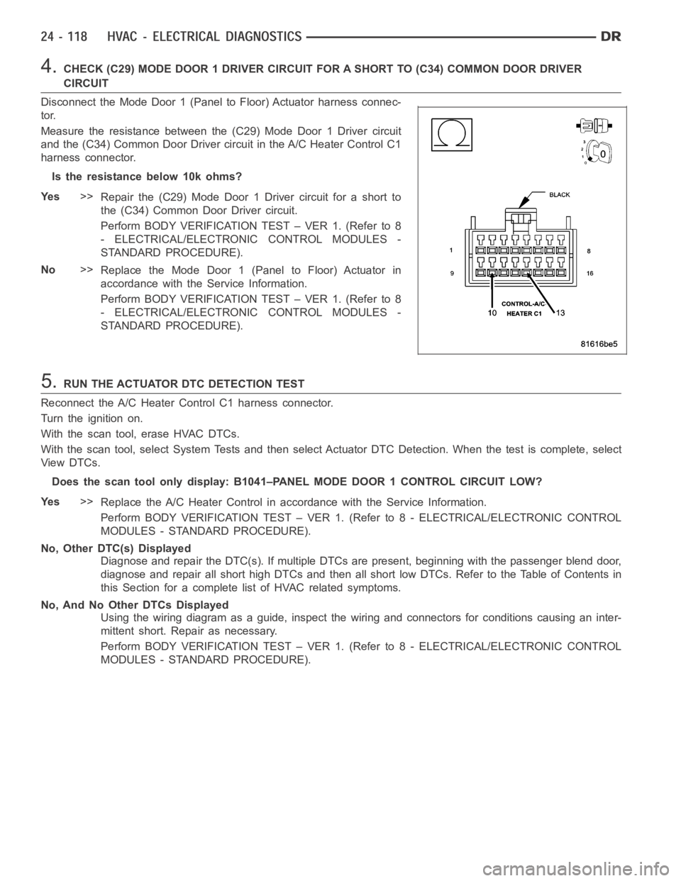
4.CHECK (C29) MODE DOOR 1 DRIVER CIRCUIT FOR A SHORT TO (C34) COMMON DOOR DRIVER
CIRCUIT
Disconnect the Mode Door 1 (Panel to Floor) Actuator harness connec-
tor.
Measure the resistance between the (C29) Mode Door 1 Driver circuit
and the (C34) Common Door Driver circuit in the A/C Heater Control C1
harness connector.
Istheresistancebelow10kohms?
Ye s>>
Repair the (C29) Mode Door 1 Driver circuit for a short to
the (C34) Common Door Driver circuit.
Perform BODY VERIFICATION TEST – VER 1. (Refer to 8
- ELECTRICAL/ELECTRONIC CONTROL MODULES -
STANDARD PROCEDURE).
No>>
Replace the Mode Door 1 (Panel to Floor) Actuator in
accordance with the Service Information.
Perform BODY VERIFICATION TEST – VER 1. (Refer to 8
- ELECTRICAL/ELECTRONIC CONTROL MODULES -
STANDARD PROCEDURE).
5.RUN THE ACTUATOR DTC DETECTION TEST
Reconnect the A/C Heater Control C1 harness connector.
Turn the ignition on.
With the scan tool, erase HVAC DTCs.
With the scan tool, select System Tests and then select Actuator DTC Detection. When the test is complete, select
View DTCs.
Does the scan tool only display: B1041–PANEL MODE DOOR 1 CONTROL CIRCUIT LOW?
Ye s>>
Replace the A/C Heater Control in accordance with the Service Information.
Perform BODY VERIFICATION TEST – VER 1. (Refer to 8 - ELECTRICAL/ELECTRONIC CONTROL
MODULES - STANDARD PROCEDURE).
No, Other DTC(s) Displayed
Diagnose and repair the DTC(s). If multiple DTCs are present, beginning with the passenger blend door,
diagnose and repair all short high DTCs and then all short low DTCs. Refer tothe Table of Contents in
this Section for a complete list of HVAC related symptoms.
No, And No Other DTCs Displayed
Using the wiring diagram as a guide, inspect the wiring and connectors for conditions causing an inter-
mittent short. Repair as necessary.
Perform BODY VERIFICATION TEST – VER 1. (Refer to 8 - ELECTRICAL/ELECTRONIC CONTROL
MODULES - STANDARD PROCEDURE).
Page 4963 of 5267
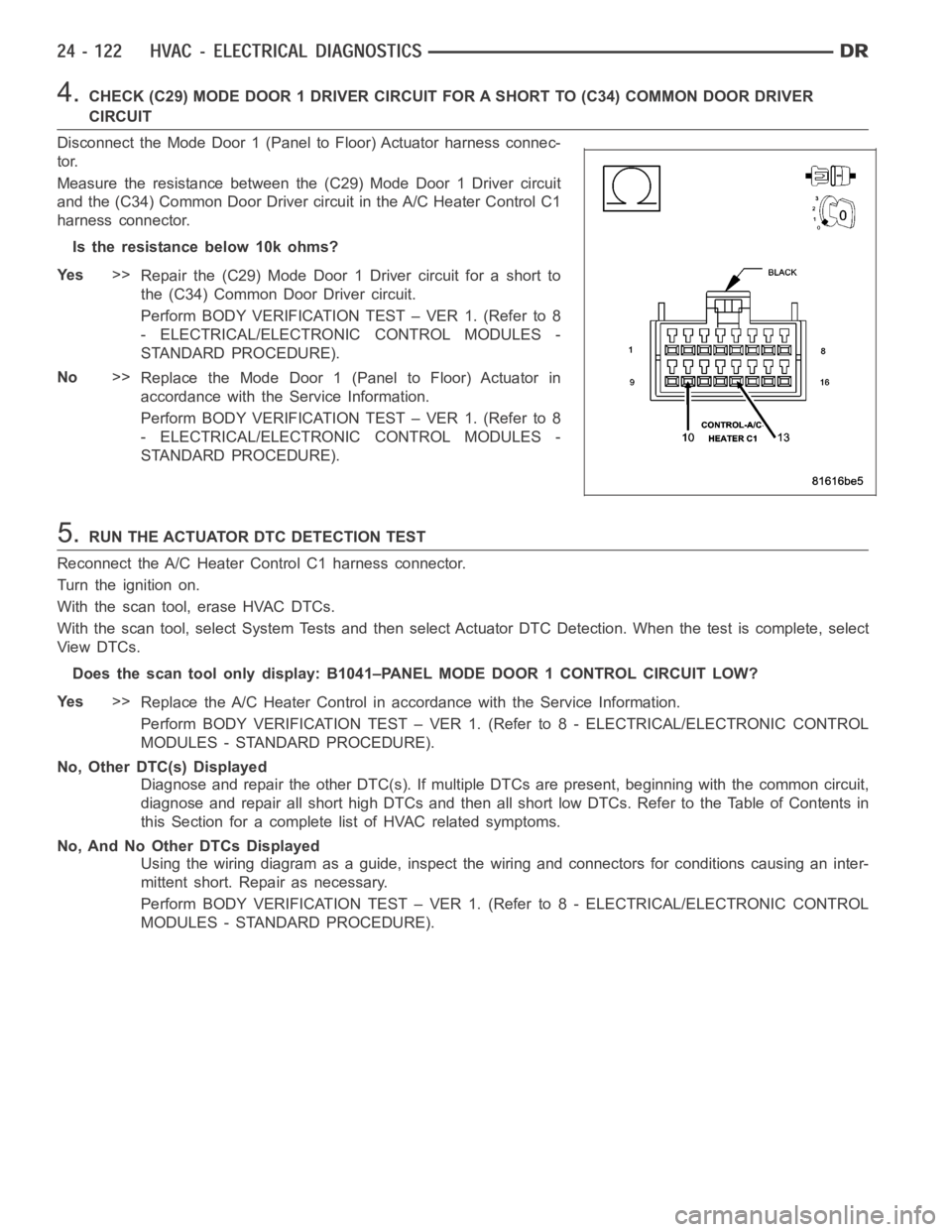
4.CHECK (C29) MODE DOOR 1 DRIVER CIRCUIT FOR A SHORT TO (C34) COMMON DOOR DRIVER
CIRCUIT
Disconnect the Mode Door 1 (Panel to Floor) Actuator harness connec-
tor.
Measure the resistance between the (C29) Mode Door 1 Driver circuit
and the (C34) Common Door Driver circuit in the A/C Heater Control C1
harness connector.
Istheresistancebelow10kohms?
Ye s>>
Repair the (C29) Mode Door 1 Driver circuit for a short to
the (C34) Common Door Driver circuit.
Perform BODY VERIFICATION TEST – VER 1. (Refer to 8
- ELECTRICAL/ELECTRONIC CONTROL MODULES -
STANDARD PROCEDURE).
No>>
Replace the Mode Door 1 (Panel to Floor) Actuator in
accordance with the Service Information.
Perform BODY VERIFICATION TEST – VER 1. (Refer to 8
- ELECTRICAL/ELECTRONIC CONTROL MODULES -
STANDARD PROCEDURE).
5.RUN THE ACTUATOR DTC DETECTION TEST
Reconnect the A/C Heater Control C1 harness connector.
Turn the ignition on.
With the scan tool, erase HVAC DTCs.
With the scan tool, select System Tests and then select Actuator DTC Detection. When the test is complete, select
View DTCs.
Does the scan tool only display: B1041–PANEL MODE DOOR 1 CONTROL CIRCUIT LOW?
Ye s>>
Replace the A/C Heater Control in accordance with the Service Information.
Perform BODY VERIFICATION TEST – VER 1. (Refer to 8 - ELECTRICAL/ELECTRONIC CONTROL
MODULES - STANDARD PROCEDURE).
No, Other DTC(s) Displayed
Diagnose and repair the other DTC(s). If multiple DTCs are present, beginning with the common circuit,
diagnose and repair all short high DTCs and then all short low DTCs. Refer tothe Table of Contents in
this Section for a complete list of HVAC related symptoms.
No, And No Other DTCs Displayed
Using the wiring diagram as a guide, inspect the wiring and connectors for conditions causing an inter-
mittent short. Repair as necessary.
Perform BODY VERIFICATION TEST – VER 1. (Refer to 8 - ELECTRICAL/ELECTRONIC CONTROL
MODULES - STANDARD PROCEDURE).