2006 DODGE RAM SRT-10 ECO mode
[x] Cancel search: ECO modePage 5061 of 5267
ACTUATOR-BLEND DOOR
DESCRIPTION
The blend door actuators are reversible, 12-volt direct
current (DC), servo motors. Models with the single
zone heating-A/C system have a single blend-air door,
which is controlled by a single blend door actuator.
Models with the dual zone system have two blend-air
doors, which are controlled by two blend door actua-
tors.
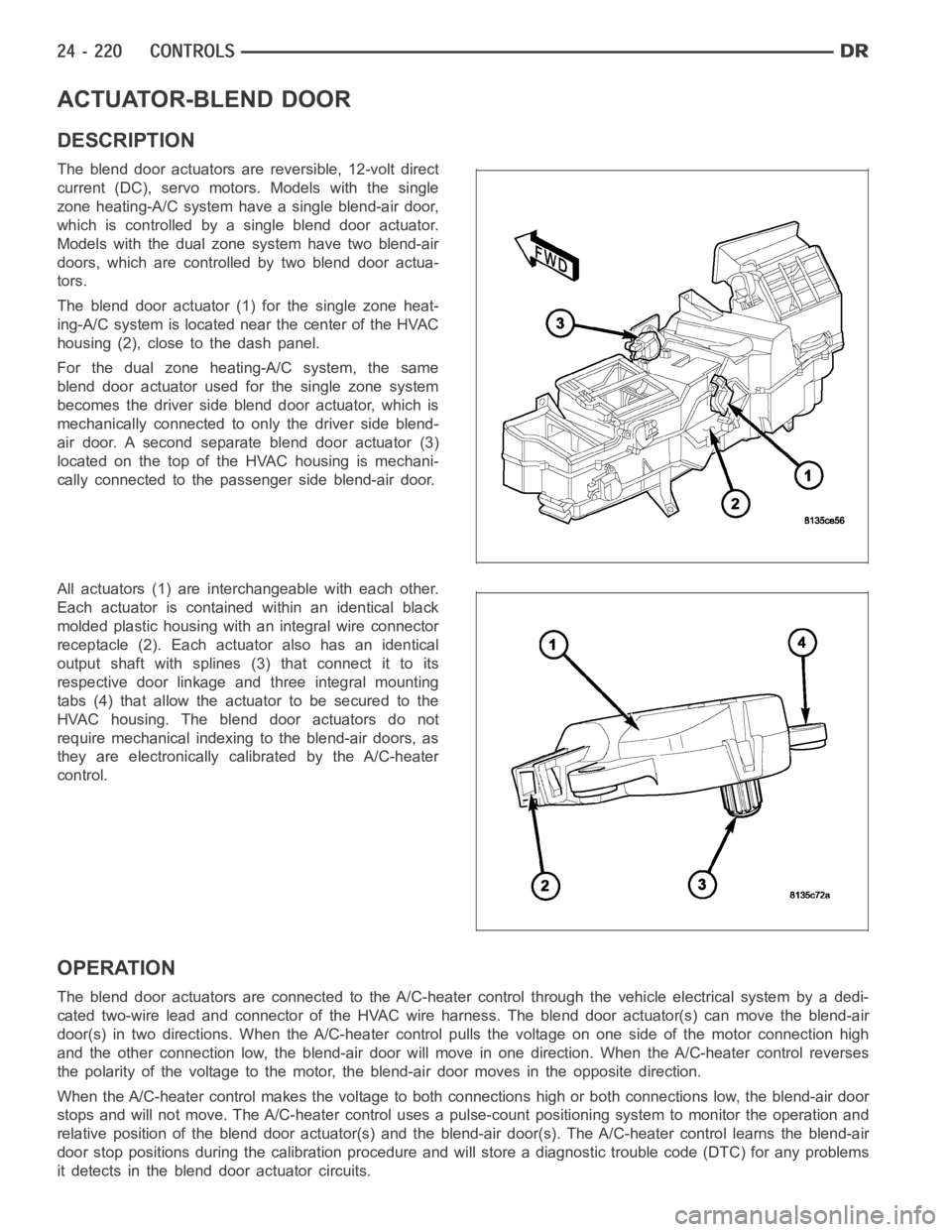
The blend door actuator (1) for the single zone heat-
ing-A/C system is located near the center of the HVAC
housing (2), close to the dash panel.
For the dual zone heating-A/C system, the same
blend door actuator used for the single zone system
becomes the driver side blend door actuator, which is
mechanically connected to only the driver side blend-
air door. A second separate blend door actuator (3)
located on the top of the HVAC housing is mechani-
cally connected to the passenger side blend-air door.
All actuators (1) are interchangeable with each other.
Each actuator is contained within an identical black
molded plastic housing with an integral wire connector
receptacle (2). Each actuator also has an identical
output shaft with splines (3) that connect it to its
respective door linkage and three integral mounting
tabs (4) that allow the actuator to be secured to the
HVAC housing. The blend door actuators do not
require mechanical indexing to the blend-air doors, as
they are electronically calibrated by the A/C-heater
control.
OPERATION
The blend door actuators are connected to the A/C-heater control through the vehicle electrical system by a dedi-
cated two-wire lead and connector of the HVAC wire harness. The blend door actuator(s) can move the blend-air
door(s) in two directions. When the A/C-heater control pulls the voltage on one side of the motor connection high
and the other connection low, the blend-air door will move in one direction. When the A/C-heater control reverses
the polarity of the voltage to the motor, the blend-air door moves in the opposite direction.
When the A/C-heater control makes the voltage to both connections high or both connections low, the blend-air door
stops and will not move. The A/C-heater control uses a pulse-count positioning system to monitor the operation and
relative position of the blend door actuator(s) and the blend-air door(s). The A/C-heater control learns the blend-air
door stop positions during the calibration procedure and will store a diagnostic trouble code (DTC) for any problems
it detects in the blend door actuator circuits.
Page 5068 of 5267
INSTALLATION
NOTE: The heating-A/C system is equipped with two mode door actuators, onefor the panel/floor-air door
and one for the defrost-air door.
PANEL/FLOOR DOOR ACTUATOR
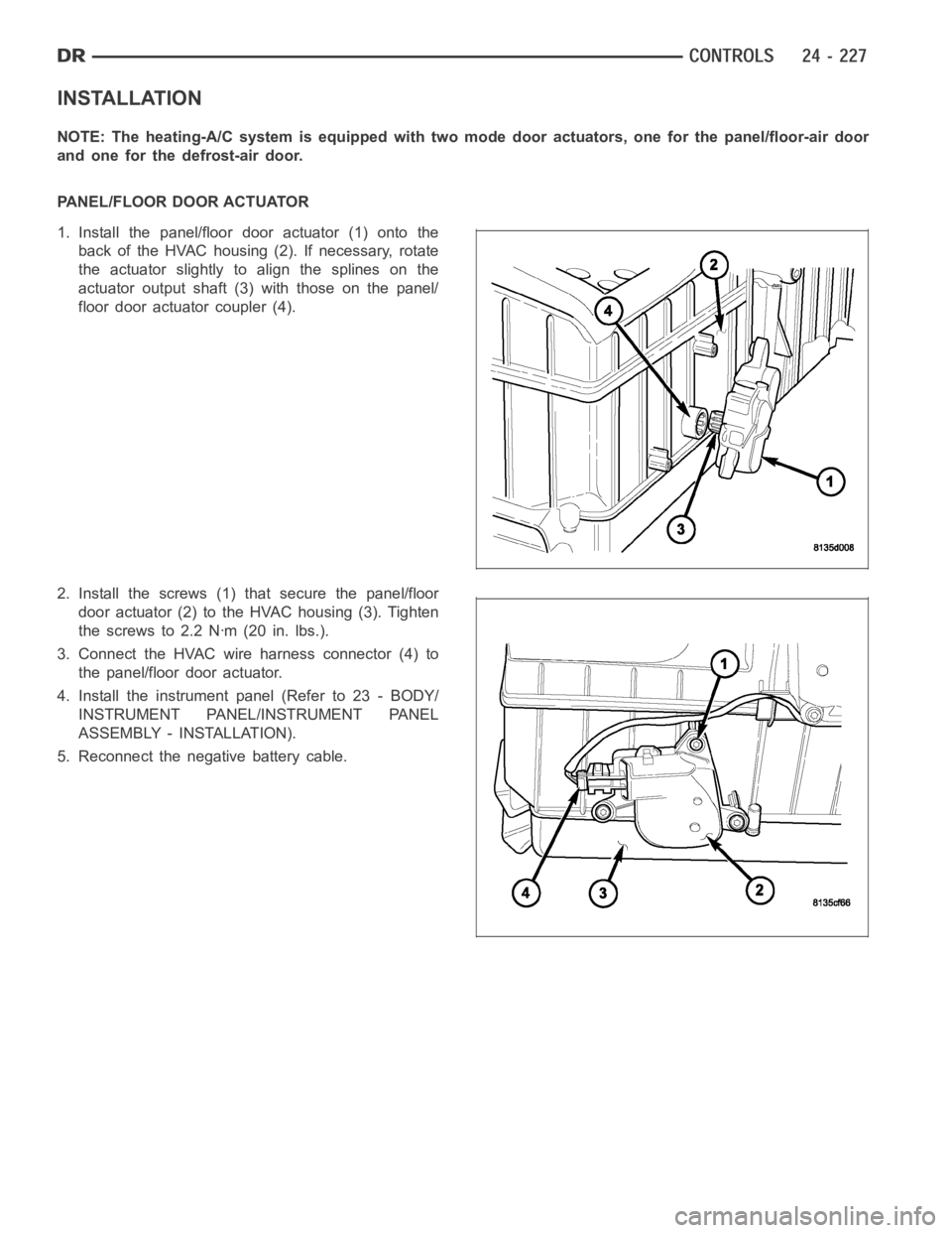
1. Install the panel/floor door actuator (1) onto the
back of the HVAC housing (2). If necessary, rotate
the actuator slightly to align the splines on the
actuator output shaft (3) with those on the panel/
floor door actuator coupler (4).
2. Install the screws (1) that secure the panel/floor
door actuator (2) to the HVAC housing (3). Tighten
the screws to 2.2 Nꞏm (20 in. lbs.).
3. Connect the HVAC wire harness connector (4) to
the panel/floor door actuator.
4. Install the instrument panel (Refer to 23 - BODY/
INSTRUMENT PANEL/INSTRUMENT PANEL
ASSEMBLY - INSTALLATION).
5. Reconnect the negative battery cable.
Page 5074 of 5267
TESTS
1. Verify the battery state of charge (Refer to 8 - ELECTRICAL/BATTERY SYSTEM/BATTERY - DIAGNOSIS AND
TESTING).
2. Connect an ammeter (0 to 10 ampere scale selected) in series with the clutch coil feed terminal. Connect a
voltmeter (0 to 20 volt scale selected) to measure voltage across the battery and the clutch coil.
3. With the A/C-heater control in the A/C mode and the blower motor at low speed, start the engine and allow it to
run at a normal idle speed.
4. The A/C compressor clutch should engage immediately, and the clutch coil supply voltage should be within two
volts of the battery voltage. If the coil supply voltage is OK, go to Step 5. If the coil supply voltage is not within
two volts of battery voltage, test the clutch coil feed circuit for excessive voltage drop and repair as necessary.
5. For the acceptable A/C clutch coil current draw specifications refer to24 - HEATING & AIR CONDITIONING -
SPECIFICATIONS. Specifications apply for a work area temperature of 21° C(70° F). If voltage is more than
12.5 volts, add electrical loads by turning on electrical accessories until voltage reads below 12.5 volts.
STANDARD PROCEDURE
A/C CLUTCH PLATE INSPECTION
NOTE: The A/C clutch can be serviced inthe vehicle. The refrigerant systemcan remain fully-charged dur-
ing compressor clutch, pulley and bearing assembly, or coil replacement.
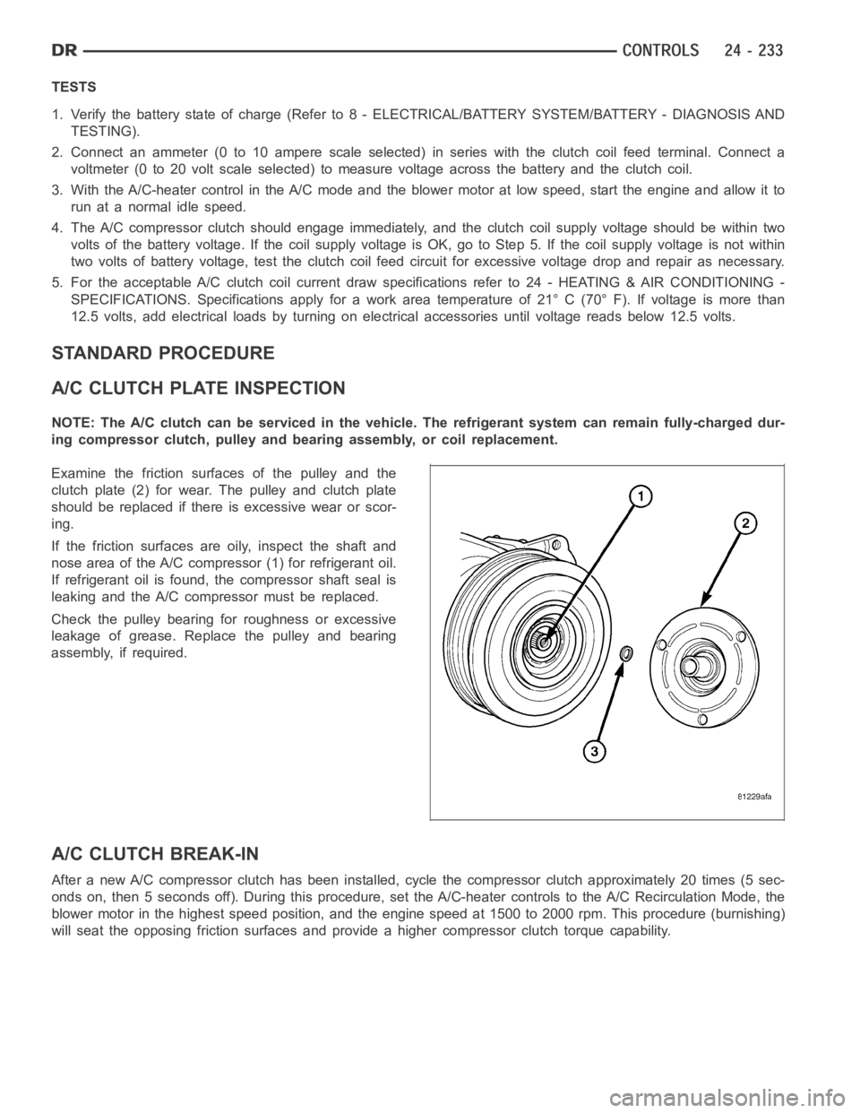
Examine the friction surfaces of the pulley and the
clutch plate (2) for wear. The pulley and clutch plate
should be replaced if there is excessive wear or scor-
ing.
If the friction surfaces are oily, inspect the shaft and
nose area of the A/C compressor (1) for refrigerant oil.
If refrigerant oil is found, the compressor shaft seal is
leaking and the A/C compressor must be replaced.
Check the pulley bearing for roughness or excessive
leakage of grease. Replace the pulley and bearing
assembly, if required.
A/C CLUTCH BREAK-IN
After a new A/C compressor clutch hasbeen installed, cycle the compressorclutch approximately 20 times (5 sec-
onds on, then 5 seconds off). During this procedure, set the A/C-heater controls to the A/C Recirculation Mode, the
blower motor in the highest speed position, and the engine speed at 1500 to 2000 rpm. This procedure (burnishing)
will seat the opposing friction surfaces and provide a higher compressor clutch torque capability.
Page 5081 of 5267
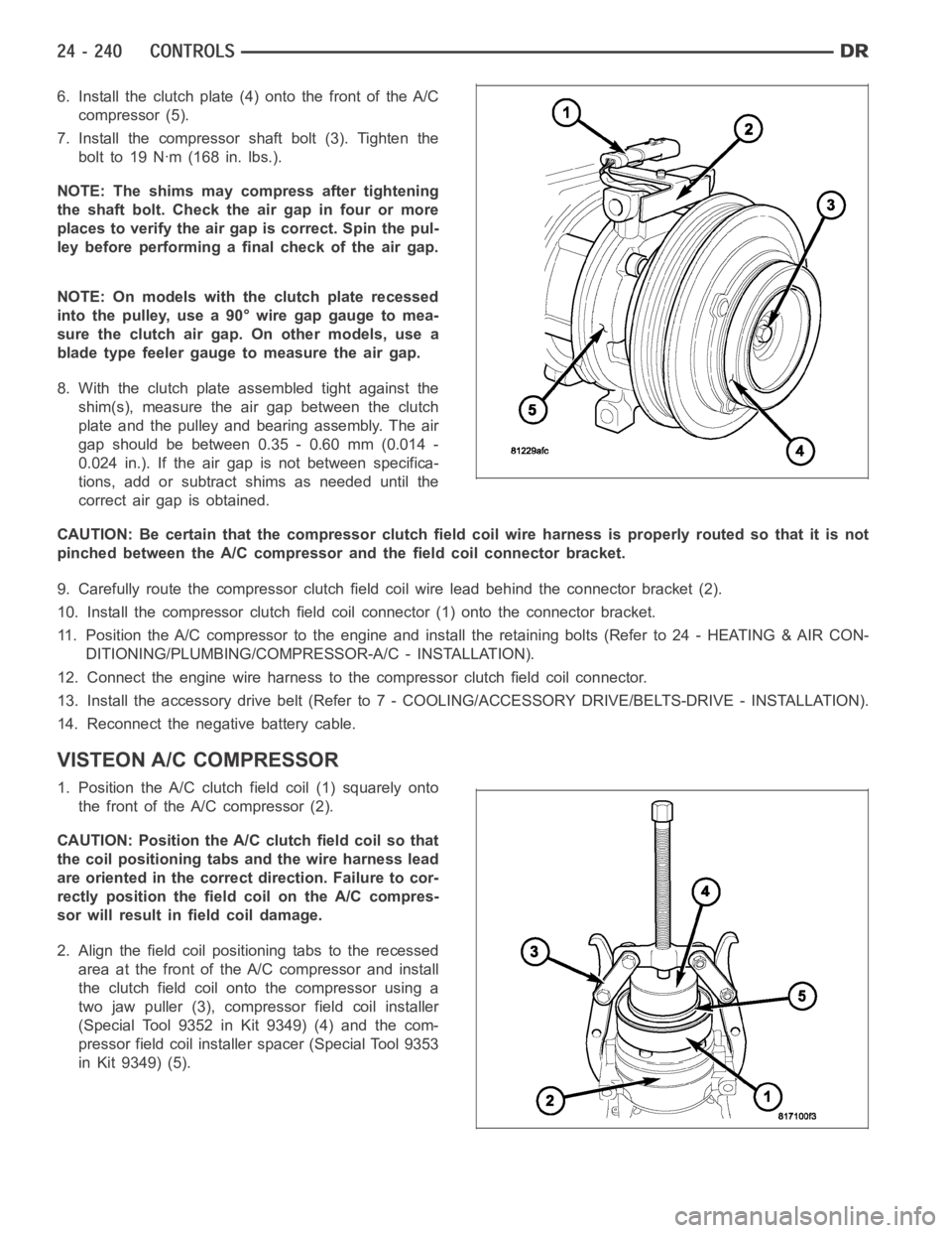
6. Install the clutch plate (4) onto the front of the A/C
compressor (5).
7. Install the compressor shaft bolt (3). Tighten the
bolt to 19 Nꞏm (168 in. lbs.).
NOTE: The shims may compress after tightening
the shaft bolt. Check the air gap in four or more
places to verify the air gap is correct. Spin the pul-
ley before performing a final check of the air gap.
NOTE: On models with the clutch plate recessed
intothepulley,usea90°wiregapgaugetomea-
sure the clutch air gap. On other models, use a
blade type feeler gauge to measure the air gap.
8. With the clutch plate assembled tight against the
shim(s), measure the air gap between the clutch
plate and the pulley and bearing assembly. The air
gap should be between 0.35 - 0.60 mm (0.014 -
0.024 in.). If the air gap is not between specifica-
tions, add or subtract shims as needed until the
correct air gap is obtained.
CAUTION: Be certain that the compressor clutch field coil wire harness is properly routed so that it is not
pinched between the A/C compressor and the field coil connector bracket.
9. Carefully route the compressor clutch field coil wire lead behind the connector bracket (2).
10. Install the compressor clutch fieldcoil connector (1) onto the connector bracket.
11. Position the A/C compressor to the engine and install the retaining bolts (Refer to 24 - HEATING & AIR CON-
DITIONING/PLUMBING/COMPRESSOR-A/C - INSTALLATION).
12. Connect the engine wire harness to the compressor clutch field coil connector.
13. Install the accessory drive belt (Refer to 7 - COOLING/ACCESSORY DRIVE/BELTS-DRIVE - INSTALLATION).
14. Reconnect the negative battery cable.
VISTEON A/C COMPRESSOR
1. Position the A/C clutch field coil (1) squarely onto
the front of the A/C compressor (2).
CAUTION: Position the A/C clutch field coil so that
the coil positioning tabs and the wire harness lead
are oriented in the correct direction. Failure to cor-
rectly position the fieldcoil on the A/C compres-
sor will result in field coil damage.
2. Align the field coil positioning tabs to the recessed
area at the front of the A/C compressor and install
the clutch field coil onto the compressor using a
two jaw puller (3), compressor field coil installer
(Special Tool 9352 in Kit 9349) (4) and the com-
pressor field coil installer spacer (Special Tool 9353
in Kit 9349) (5).
Page 5104 of 5267
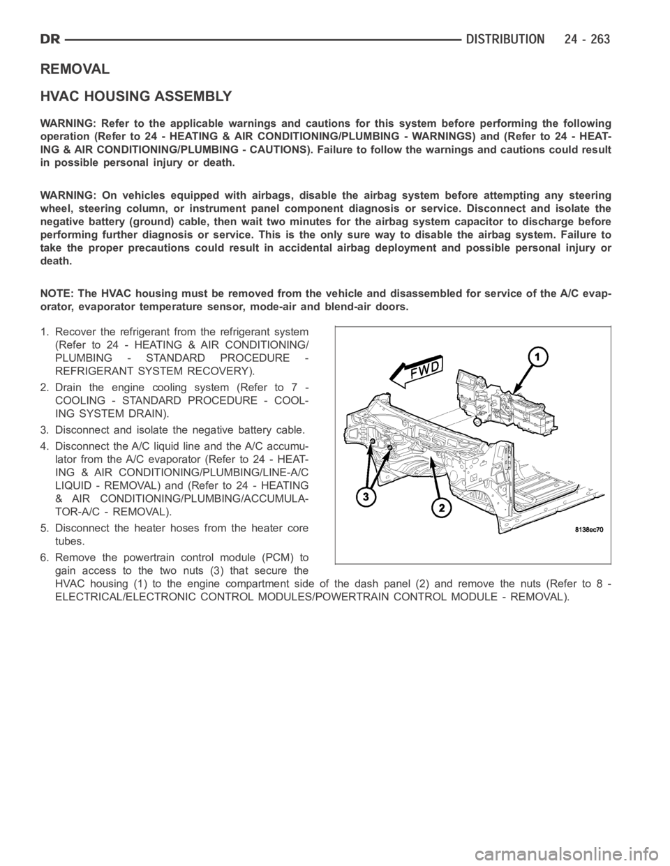
REMOVAL
HVAC HOUSING ASSEMBLY
WARNING: Refer to the applicable warnings and cautions for this system before performing the following
operation (Refer to 24 - HEATING & AIR CONDITIONING/PLUMBING - WARNINGS) and (Refer to 24 - HEAT-
ING & AIR CONDITIONING/PLUMBING - CAUTIONS). Failure to follow the warnings and cautions could result
in possible personal injury or death.
WARNING: On vehicles equipped with airbags, disable the airbag system before attempting any steering
wheel, steering column, or instrument panel component diagnosis or service. Disconnect and isolate the
negative battery (ground) cable, then wait two minutes for the airbag system capacitor to discharge before
performing further diagnosis or service. This is the only sure way to disable the airbag system. Failure to
take the proper precautions could result in accidental airbag deploymentand possible personal injury or
death.
NOTE: The HVAC housing must be removedfrom the vehicle and disassembled for service of the A/C evap-
orator, evaporator temperature sensor, mode-air and blend-air doors.
1. Recover the refrigerant from the refrigerant system
(Refer to 24 - HEATING & AIR CONDITIONING/
PLUMBING - STANDARD PROCEDURE -
REFRIGERANT SYSTEM RECOVERY).
2. Drain the engine cooling system (Refer to 7 -
COOLING - STANDARD PROCEDURE - COOL-
ING SYSTEM DRAIN).
3. Disconnect and isolate the negative battery cable.
4. Disconnect the A/C liquid line and the A/C accumu-
lator from the A/C evaporator (Refer to 24 - HEAT-
ING & AIR CONDITIONING/PLUMBING/LINE-A/C
LIQUID - REMOVAL) and (Refer to 24 - HEATING
& AIR CONDITIONING/PLUMBING/ACCUMULA-
TOR-A/C - REMOVAL).
5. Disconnect the heater hoses from the heater core
tubes.
6. Remove the powertrain control module (PCM) to
gain access to the two nuts (3) that secure the
HVAC housing (1) to the engine compartment side of the dash panel (2) and remove the nuts (Refer to 8 -
ELECTRICAL/ELECTRONIC CONTROL MODULES/POWERTRAIN CONTROL MODULE - REMOVAL).
Page 5119 of 5267
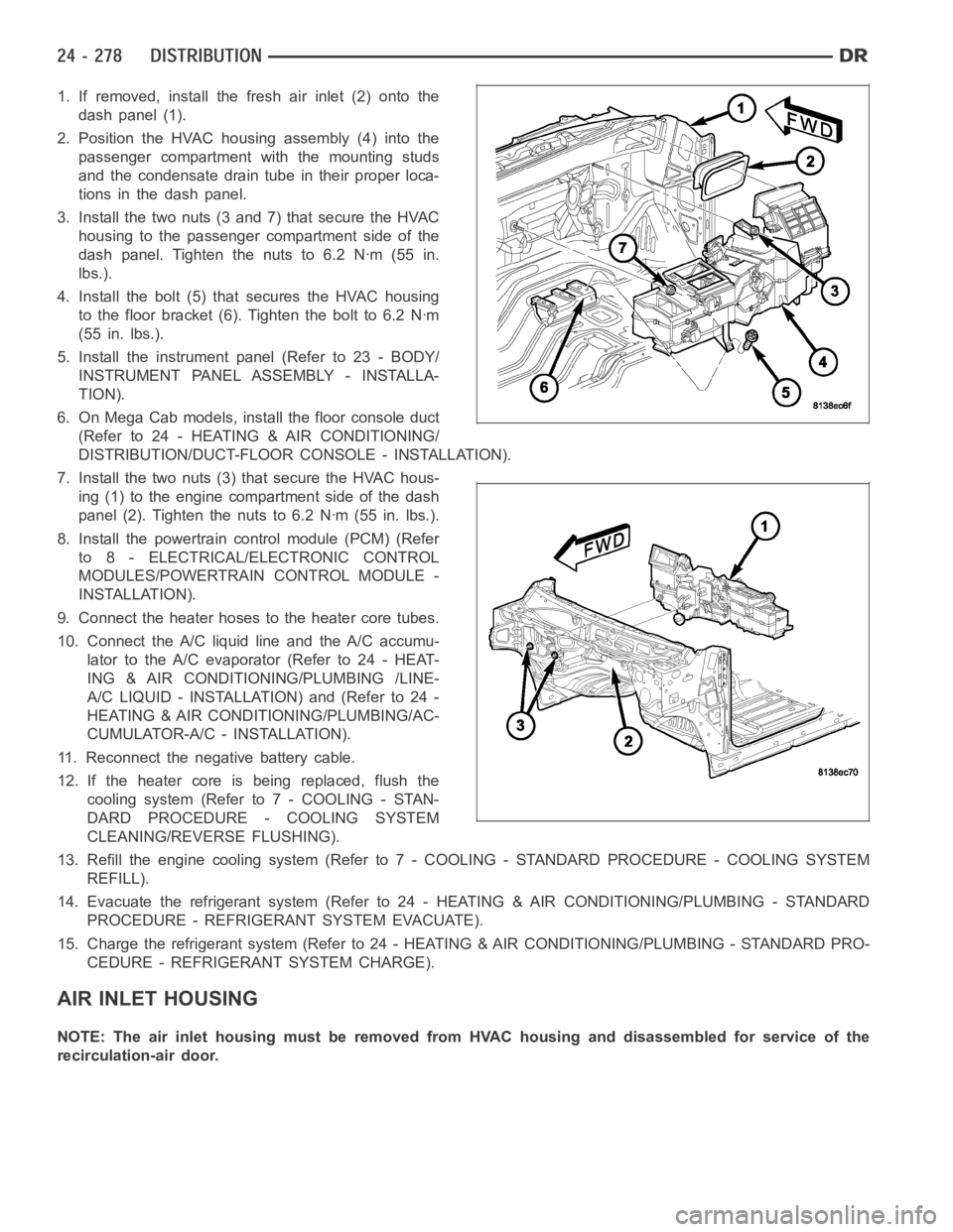
1. If removed, install the fresh air inlet (2) onto the
dash panel (1).
2. Position the HVAC housing assembly (4) into the
passenger compartment with the mounting studs
and the condensate drain tube in their proper loca-
tions in the dash panel.
3. Install the two nuts (3 and 7) that secure the HVAC
housing to the passenger compartment side of the
dash panel. Tighten the nuts to 6.2 Nꞏm (55 in.
lbs.).
4. Install the bolt (5) that secures the HVAC housing
to the floor bracket (6). Tighten the bolt to 6.2 Nꞏm
(55 in. lbs.).
5. Install the instrument panel (Refer to 23 - BODY/
INSTRUMENT PANEL ASSEMBLY - INSTALLA-
TION).
6. On Mega Cab models, install the floor console duct
(Refer to 24 - HEATING & AIR CONDITIONING/
DISTRIBUTION/DUCT-FLOOR CONSOLE - INSTALLATION).
7. Install the two nuts (3) that secure the HVAC hous-
ing (1) to the engine compartment side of the dash
panel (2). Tighten the nuts to 6.2 Nꞏm (55 in. lbs.).
8. Install the powertrain control module (PCM) (Refer
to 8 - ELECTRICAL/ELECTRONIC CONTROL
MODULES/POWERTRAIN CONTROL MODULE -
INSTALLATION).
9. Connect the heater hoses to the heater core tubes.
10. Connect the A/C liquid line and the A/C accumu-
lator to the A/C evaporator (Refer to 24 - HEAT-
ING & AIR CONDITIONING/PLUMBING /LINE-
A/C LIQUID - INSTALLATION) and (Refer to 24 -
HEATING & AIR CONDITIONING/PLUMBING/AC-
CUMULATOR-A/C - INSTALLATION).
11. Reconnect the negative battery cable.
12. If the heater core is being replaced, flush the
coolingsystem(Referto7-COOLING-STAN-
DARD PROCEDURE - COOLING SYSTEM
CLEANING/REVERSE FLUSHING).
13. Refill the engine cooling system (Refer to 7 - COOLING - STANDARD PROCEDURE - COOLING SYSTEM
REFILL).
14. Evacuate the refrigerant system (Refer to 24 - HEATING & AIR CONDITIONING/PLUMBING - STANDARD
PROCEDURE - REFRIGERANT SYSTEM EVACUATE).
15. Charge the refrigerant system (Refer to 24 - HEATING & AIR CONDITIONING/PLUMBING - STANDARD PRO-
CEDURE - REFRIGERANT SYSTEM CHARGE).
AIR INLET HOUSING
NOTE: The air inlet housing must be removed from HVAC housing and disassembled for service of the
recirculation-air door.
Page 5131 of 5267
RECOVERY/RECYCLING/EVACUATION/CHARGING HOSE– The center manifold hose (Yellow, or White, with
Black stripe) (3) is used to recover, evacuate, and charge the refrigerantsystem. When the low or high pressure
valves on the manifold gauge set are opened, the refrigerant in the system will escape through this hose.
HIGH PRESSURE GAUGE HOSE– The high pressure hose (Red with Black stripe) (4) attaches to the high side
service port. This service port is located on the A/C discharge line. On this model, an A/C pressure transducer is
installed on the high side service port. A/C high-side pressures can be read using a scan tool. Refer to 9 - Engine
Electrical Diagnostics for more information.
LOW PRESSURE GAUGE HOSE– The low pressure hose (Blue with Black stripe) (5) attaches to the low side
service port. This service port is located either on the top of the A/C accumulator or on the A/C suction line near the
accumulator, depending on engine application.
REFRIGERANT SYSTEM RECOVERY
WARNING: Refer to the applicable warnings and cautions for this system before performing the following
operation (Refer to 24 - HEATING & AIR CONDITIONING/PLUMBING - WARNINGS) and (Refer to 24 - HEAT-
ING & AIR CONDITIONING/PLUMBING - CAUTIONS). Failure to follow the warnings and cautions could result
in possible personal injury or death.
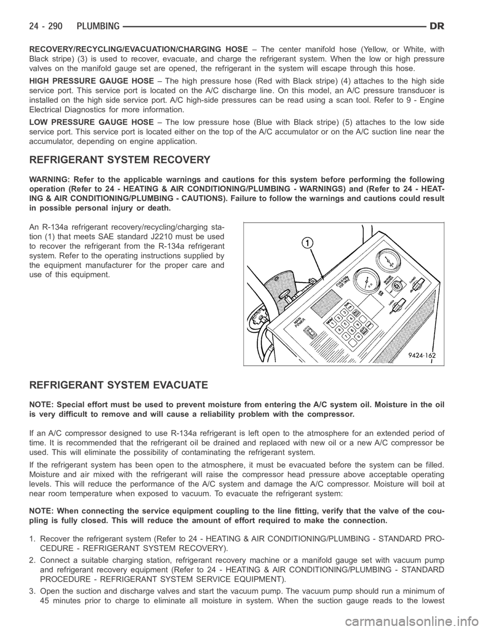
An R-134a refrigerant recovery/recycling/charging sta-
tion (1) that meets SAE standard J2210 must be used
to recover the refrigerant from the R-134a refrigerant
system. Refer to the operating instructions supplied by
the equipment manufacturer for the proper care and
use of this equipment.
REFRIGERANT SYSTEM EVACUATE
NOTE: Special effort must be used to prevent moisture from entering the A/Csystem oil. Moisture in the oil
is very difficult to remove and will cause a reliability problem with the compressor.
If an A/C compressor designed to use R-134a refrigerant is left open to the atmosphere for an extended period of
time. It is recommended that the refrigerant oil be drained and replaced with new oil or a new A/C compressor be
used. This will eliminate the possibility of contaminating the refrigerant system.
If the refrigerant system has been open to the atmosphere, it must be evacuated before the system can be filled.
Moisture and air mixed with the refrigerant will raise the compressor headpressure above acceptable operating
levels. This will reduce the performance of the A/C system and damage the A/C compressor. Moisture will boil at
near room temperature when exposed to vacuum. To evacuate the refrigerantsystem:
NOTE: When connecting the service equipment coupling to the line fitting,verify that the valve of the cou-
pling is fully closed. This will reduce the amount of effort required to make the connection.
1. Recover the refrigerant system (Refer to 24 - HEATING & AIR CONDITIONING/PLUMBING - STANDARD PRO-
CEDURE - REFRIGERANT SYSTEM RECOVERY).
2. Connect a suitable charging station, refrigerant recovery machine or amanifold gauge set with vacuum pump
and refrigerant recovery equipment (Refer to 24 - HEATING & AIR CONDITIONING/PLUMBING - STANDARD
PROCEDURE - REFRIGERANT SYSTEM SERVICE EQUIPMENT).
3. Open the suction and discharge valves and start the vacuum pump. The vacuum pump should run a minimum of
45minutespriortochargetoeliminateall moisture in system. When the suction gauge reads to the lowest
Page 5133 of 5267
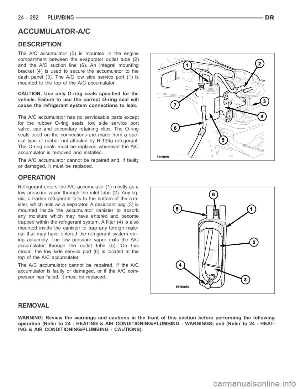
ACCUMULATOR-A/C
DESCRIPTION
The A/C accumulator (5) is mounted in the engine
compartment between the evaporator outlet tube (2)
and the A/C suction line (6). An integral mounting
bracket (4) is used to secure the accumulator to the
dash panel (3). The A/C low side service port (1) is
mountedtothetopoftheA/Caccumulator.
CAUTION: Use only O-ring seals specified for the
vehicle. Failure to use the correct O-ring seal will
cause the refrigerant system connections to leak.
The A/C accumulator has no serviceable parts except
for the rubber O-ring seals, low side service port
valve, cap and secondary retaining clips. The O-ring
seals used on the connections are made from a spe-
cial type of rubber not affected by R-134a refrigerant.
The O-ring seals must be replaced whenever the A/C
accumulator is removed and installed.
The A/C accumulator cannot be repaired and, if faulty
or damaged, it must be replaced.
OPERATION
Refrigerant enters the A/C accumulator (1) mostly as a
low pressure vapor through the inlet tube (2). Any liq-
uid, oil-laden refrigerant falls to the bottom of the can-
ister, which acts as a separator. A desiccant bag (3) is
mounted inside the accumulator canister to absorb
any moisture which may have entered and become
trapped within the refrigerant system. A filter (4) is also
mounted inside the canister to trap any foreign mate-
rial that may have entered the refrigerant system dur-
ing assembly. The low pressure vapor exits the A/C
accumulator through the outlet tube (5). On this
model, the low side service port (6) is located at the
top of the A/C accumulator.
The A/C accumulator cannot be repaired. If the A/C
accumulator is faulty or damaged, or if the A/C com-
pressor has failed, it must be replaced.
REMOVAL
WARNING: Review the warnings and cautions in the front of this section before performing the following
operation (Refer to 24 - HEATING & AIR CONDITIONING/PLUMBING - WARNINGS) and (Refer to 24 - HEAT-
ING & AIR CONDITIONING/PLUMBING - CAUTIONS).