Page 3118 of 5267

P0613-INTERNAL TCM
For a complete wiring diagramRefer to Section 8W.
Theory of Operation
The internal Watchdog (WD) is a separate hardware circuit that continuously monitors the microprocessor. To insure
the proper operation of the Transmission controller the watchdog must receive a signal from the microprocessor
within a specific time window (14 msec ± 1 msec) to prevent a system shutdownafter a short delay (570 msec).
The microprocessor periodically tests the WD’s ability to provide this shutdown function using a three phase test;
1) Send the signal too late > 15 msec
2) Send the signal too early < 13 msec
3) Delay test < 590 msec
If the watchdog input signal arrives too early or too late, the Watchdog Fault line will go low and the watchdog delay
will start to time out. The delay will be reset by the correct timing of watchdog signal sent during subsequent oper-
ations.
The Delay Test checks the delay time out. The Delay Monitor line is pulled low, which forces the delay to start timing
out. At the end of the delay time the Transmission Relay will be turned off. The delay test, upon detection of the
relay turning off, will immediately turn the relay back on before shutdowncan occur.
When Monitored:
1) One time after the controller is reset (ignition turned to the RUN position) and every 60 seconds thereafter.
The Delay Test is executed after a reset only.
2) 2 seconds after an invalid test.
Set Condition:
If either of the following conditions occur 3 times:
1) The watchdog fault line remains high after the period has elapsed for thetoo early - too late watchdog test.
2) The Transmission Control Relay remains on after the watchdog delay expired.
Possible Causes
POWERORGROUNDCIRCUIT
POWERTRAIN CONTROL MODULE
Always perform the Pre-Diagnostic Troubleshooting procedure before proceeding. (Refer to 21 - TRANSMIS-
SION/TRANSAXLE/AUTOMATIC - 45RFE/545RFE - STANDARD PROCEDURE)
Diagnostic Test
1.CHECK THE WIRING AND CONNECTORS
Using the schematics as a guide, check the Powertrain Control Module (PCM)terminals for corrosion, damage, or
terminal push out. Pay particular attention to all power and ground circuits.
NOTE: Due to the integration of the Powertrain and Transmission Control Modules, the transmission part of
the PCM has it’s own specific power and ground circuits.
Wiggle the wires while checking for shorted and open circuits.
Check for any Service Bulletins that may apply.
Were there any problems found?
Ye s>>
Repair the power and/or ground circuits as necessary.
Perform 45RFE/545RFE TRANSMISSION VERIFICATION TEST - VER 1. (Refer to 21- TRANSMIS-
SION/TRANSAXLE/AUTOMATIC - 45RFE/545RFE - STANDARD PROCEDURE)
No>>
Replace the PCM per the Service Information. With the scan tool, perform QUICK LEARN.
Perform 45RFE/545RFE TRANSMISSION VERIFICATION TEST - VER 1. (Refer to 21- TRANSMIS-
SION/TRANSAXLE/AUTOMATIC - 45RFE/545RFE - STANDARD PROCEDURE)
Page 3119 of 5267
P0706-TRANSMISSION RANGE SENSOR RATIONALITY
For a complete wiring diagramRefer to Section 8W.
Page 3122 of 5267

5.TRS SENSE CIRCUIT SHORT TO OTHER CIRCUITS
Measure the resistance between the identified (T1, T2, T3, T41, or T42) TRSSense circuit and all other circuits in
the Transmission Solenoid/TRS Assembly harness connector.
Is the resistance below 100k ohms between the identified (T1, T2, T3, T41, or T42) TRS Sense circuit
and any other circuit(s) in the Transmission Solenoid/TRS Assembly harness connector?
Ye s>>
Repair the identified (T1, T2, T3, T41,orT42)TRSSensecircuitforashortto other circuit(s).
Perform 45RFE/545RFE TRANSMISSION VERIFICATION TEST - VER 1. (Refer to 21- TRANSMIS-
SION/TRANSAXLE/AUTOMATIC - 45RFE/545RFE - STANDARD PROCEDURE)
No>>
Using the schematics as a guide, check the Powertrain Control Module (PCM)terminals for corrosion,
damage, or terminal push out. Pay particular attention to all power and ground circuits. If no problems
are found, replace the PCM per the Service Information. With the scan tool,perform QUICK LEARN.
Perform 45RFE/545RFE TRANSMISSION VERIFICATION TEST - VER 1. (Refer to 21- TRANSMIS-
SION/TRANSAXLE/AUTOMATIC - 45RFE/545RFE - STANDARD PROCEDURE)
6.INTERMITTENT WIRING AND CONNECTORS
The conditions necessary to set the DTC are not present at this time.
Using the schematics as a guide, inspect the wiring and connectors specifictothiscircuit.
Wiggle the wiring and connectors while checking for shorted and open circuits.
With the scan tool, check the DTC EVENT DATA to help identify the conditionsin which the DTC was set.
Were there any problems found?
Ye s>>
Repair as necessary.
Perform 45RFE/545RFE TRANSMISSION VERIFICATION TEST - VER 1. (Refer to 21- TRANSMIS-
SION/TRANSAXLE/AUTOMATIC - 45RFE/545RFE - STANDARD PROCEDURE)
No>>
Te s t C o m p l e t e .
Page 3123 of 5267
P0711-TRANSMISSION TEMPERATURE SENSOR PERFORMANCE
For a complete wiring diagramRefer to Section 8W.
Page 3125 of 5267

Compare the scan tool readings to the voltage readings listed on the Transmission Simulator.
Do the readings on the scan tool match the Transmission Simulator readings± 0.2 volts?
Ye s>>
Replace Transmission Solenoid/TRS Assembly per the Service Information.
Perform 45RFE/545RFE TRANSMISSION VERIFICATION TEST - VER 1. (Refer to 21- TRANSMIS-
SION/TRANSAXLE/AUTOMATIC - 45RFE/545RFE - STANDARD PROCEDURE)
No>>
Using the schematics as a guide, check the Powertrain Control Module (PCM)terminals for corrosion,
damage, or terminal push out. Pay particular attention to all power and ground circuits. If no problems
are found, replace the PCM per the Service Information. With the scan tool,perform QUICK LEARN.
Perform 45RFE/545RFE TRANSMISSION VERIFICATION TEST - VER 1. (Refer to 21- TRANSMIS-
SION/TRANSAXLE/AUTOMATIC - 45RFE/545RFE - STANDARD PROCEDURE)
4.INTERMITTENT WIRING AND CONNECTORS
The conditions necessary to set this DTC are not present at this time.
Using the schematics as a guide, inspect the wiring and connectors specifictothiscircuit.
Wiggle the wires while checking for shorted and open circuits.
With the scan tool, check the DTC EVENT DATA to help identify the conditionsin which the DTC was set.
Were there any problems found?
Ye s>>
Repair as necessary.
Perform 45RFE/545RFE TRANSMISSION VERIFICATION TEST - VER 1. (Refer to 21- TRANSMIS-
SION/TRANSAXLE/AUTOMATIC - 45RFE/545RFE - STANDARD PROCEDURE)
No>>
Te s t C o m p l e t e .
Page 3126 of 5267
P0712-TRANSMISSION TEMPERATURE SENSOR LOW
For a complete wiring diagramRefer to Section 8W.
Page 3128 of 5267

Compare the scan tool readings with the numbers listed on the TransmissionSimulator.
Do the readings on the Transmission Simulator match the scan tool readings± 0.2 volts?
Ye s>>
Replace Transmission Solenoid/TRS Assembly per the Service Information.
Perform 45RFE/545RFE TRANSMISSION VERIFICATION TEST - VER 1. (Refer to 21- TRANSMIS-
SION/TRANSAXLE/AUTOMATIC - 45RFE/545RFE - STANDARD PROCEDURE)
No>>
Go To 4
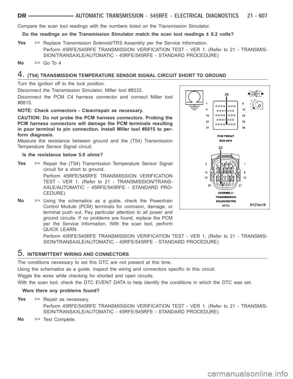
4.(T54) TRANSMISSION TEMPERATURE SENSOR SIGNAL CIRCUIT SHORT TO GROUND
Turn the ignition off to the lock position.
Disconnect the Transmission Simulator, Miller tool #8333.
Disconnect the PCM C4 harness connector and connect Miller tool
#8815.
NOTE: Check connectors - Clean/repair as necessary.
CAUTION: Do not probe the PCM harness connectors. Probing the
PCM harness connectors will damage the PCM terminals resulting
in poor terminal to pin connection. Install Miller tool #8815 to per-
form diagnosis.
Measure the resistance between ground and the (T54) Transmission
Temperature Sensor Signal circuit.
Is the resistance below 5.0 ohms?
Ye s>>
Repair the (T54) Transmission Temperature Sensor Signal
circuit for a short to ground.
Perform 45RFE/545RFE TRANSMISSION VERIFICATION
TEST - VER 1. (Refer to 21 - TRANSMISSION/TRANS-
AXLE/AUTOMATIC - 45RFE/545RFE - STANDARD PRO-
CEDURE)
No>>
Using the schematics as a guide, check the Powertrain
Control Module (PCM) terminals for corrosion, damage, or
terminal push out. Pay particular attention to all power and
ground circuits. If no problems are found, replace the PCM
per the Service Information.With the scan tool, perform
QUICK LEARN.
Perform 45RFE/545RFE TRANSMISSION VERIFICATION TEST - VER 1. (Refer to 21- TRANSMIS-
SION/TRANSAXLE/AUTOMATIC - 45RFE/545RFE - STANDARD PROCEDURE)
5.INTERMITTENT WIRING AND CONNECTORS
The conditions necessary to set this DTC are not present at this time.
Using the schematics as a guide, inspect the wiring and connectors specifictothiscircuit.
Wiggle the wires while checking for shorted and open circuits.
With the scan tool, check the DTC EVENT DATA to help identify the conditionsin which the DTC was set.
Were there any problems found?
Ye s>>
Repair as necessary.
Perform 45RFE/545RFE TRANSMISSION VERIFICATION TEST - VER 1. (Refer to 21- TRANSMIS-
SION/TRANSAXLE/AUTOMATIC - 45RFE/545RFE - STANDARD PROCEDURE)
No>>
Te s t C o m p l e t e .
Page 3129 of 5267
P0713-TRANSMISSION TEMPERATURE SENSOR HIGH
For a complete wiring diagramRefer to Section 8W.